Raghavaiah Katuri* | Srinivasarao Gorantla
OPEN ACCESS
Hybrid Energy Storage System (HESS) has been introduced by combining battery with Ultracapacitor (UC). Both battery and UC are having quite opposite characteristics. The high power density of UC can be utilized during transient as well as cold starting conditions of the electric motor, and the battery can fill full its work during normal conditions. Smooth switching between battery and UC is the main obstacle associated with HESS powered electric vehicles. The main objective of the proposed work is to design and suggest a good controller for smooth switching of energy sources in HESS. A new controller has been designed with four math functions, which are individually coded based on the speed of an electric motor, called as Math Function Based (MFB) controller. To achieve a smooth transition between battery and UC, the designed MFB has been integrated with different conventional and intelligent controllers, made different hybrid controllers. In this work totally four hybrid controllers named MFB plus PI, MFB plus PID, MFB plus Fuzzy logic and MFB plus artificial neural network (ANN) controllers have been implemented to the overall circuit in four modes. Finally, suggest one hybrid controller based on the comparative analysis of all hybrid controllers. The MATLAB/ Simulation results have been plotted and discussed in Simulation Results and discussion section.
bidirectional converter (BDC), unidirectional converter (UDC), battery, ultracapacitor (UC), MFB controller, proportional integral (PI) controller, proportional integral derivative (PID) controller, fuzzy logic controller, ANN controller
In recent years, production of greenhouse effect gases is increased more drastically, this was mainly due to increased population usage of conventional IC engine vehicles. Traditionally battery/fuel cell powered an electric vehicle has been introduced, but this attempt has not given effective results due to some drawbacks like driving range and unable to generate peak power during transient conditions. HEVs have been introduced in order to avoid driving range problem. After that HESS has designed combining battery with UC. Here the high-power density of UC can be utilized during peak power requirement’s in order to improve the life of the battery [1-14].
An adaptive fuzzy logic controller technique has been suggested for proper energy management between battery and UC. This can be achieved by providing driver requirements as an input to the Fuzzy logic controller [1]. To overcome energy management problem of energy sources in HESS in more precise way Metafiction based controller has been designed and implemented with a conventional controller, based on the speed of an electric motor. Here the control technique mainly happens due to speed changes only [2-3]. A supervisory energy management technique has been used for proper energy splitting between the battery and UC with real-time implementation control [4]. A small urban vehicle is implemented with real-time multiple energy sources, the energy management can be done based on the rule-based method. Optimal energy sharing obtained with particle swarm optimization approach [5]. A fuzzy logic supervisory wavelet-transform frequency decoupling-based energy management approach realized for balancing the energy of multiple sources in the electrified vehicle for reducing the size of electric vehicle size and enhancing the life of major source [6]. The tramway has been implemented with three energy sources like a battery, fuel cell, and a supercapacitor, these sources controlling can be achieved by the predictive control method. In this different source are connected to the dc-dc converter through dc bus [7]. Zero voltage transition (ZVT) has been applied to BDC in order to achieve proper switching between battery and UC. With ZVT almost soft switching performed comparing to the normal PWM method [8]. A new HESS has been proposed with a low rating of dc to dc converters to reduce the size of the overall system for electric vehicles further, this can be validated with conventional HESS [9]. To know the behavior of supercapacitor and the modeling of the energy storage system can be done base on the polynomial control method [10].
The main aim of this work is to design an efficient controller for HESS powered HEVs or EVs, which will able to switch the battery and UC according to the electric vehicle dynamics. In this work, a new MFB controller has designed based on the speed of the electric motor.
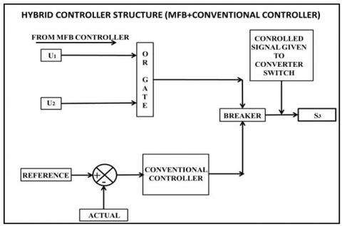
The block diagram representation of proposed HESS has been represented with Figure 1. Here battery has been linked to a UDC; UC has been linked to a BDC. MFB is used to generates pulse which has given to the circuit breaker, this controller will work based on the electric motor speed. The conventional controller is used to keeping the regular voltage profile at the electrical motor give up. MFB and conventional as well as intelligent controllers output can be compared at the circuit breaker, relying on the speed of the motor pulse indicators had been generated to unique transfer that can be S1, S2, and S3. Subsequently, the mixture of MFB with a different conventional as well as intelligent controller works together and controls the pulses of all switches in converters.
Figure 1. Proposed block diagram model of the hybrid energy storage system
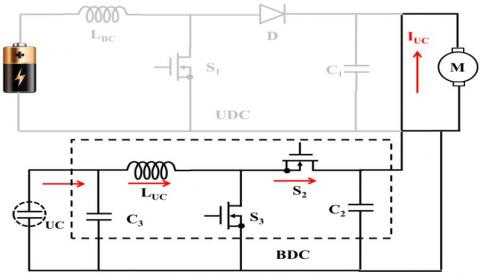
Figure 2. Converter model circuit diagram with HESS
The converter model main circuit has been represented in Figure 2. Here BDC can perform both boost mode operation as well as buck mode operation. Here buck mode operation of BDC can be useful to charge the UC from battery power and boost mode of UDC, as well as BDC, is used to propel the electric vehicle during peak and normal mode conditions depending upon the speed of the electric motor. Here BDC has two switches namely S2 and S3, and UDC having only one switch S1. In this work, all switches are taken as MOSFETs only.
In this work MFB controller acts as a universal controller, this can be designed with four modes which always depending upon the speed of the electric motor. This controller combined with other conventional as well as intelligent controllers and made different hybrid controllers for the successive smooth transition between the battery and UC. MFB controller always decides the gate signal to the particular switch which can be generated by the other combined controller, which means the designed MFB controller, plays a vital role in the smooth switching of energy sources in HESS. The four math functions generate the pulse signals based on the speed of the motor as follows further this signal can control the gate signal of particular switches in the converters.
(i) If the speed of the motor is less than or equal to 4800 rpm then MFB generates signal U1 as 1.
(ii) If the speed is in between 4600 rpm to 4800 rpm then MFB generates signals U1 and U2 as 1.
(iii) If the speed of the motor lies between 4801rpm to 4930 rpm MFB generates signal U3 as 1.
(iv) If the speed of the motor is greater than or equal to 4931 rpm MFB generates signal U4 as 1.
All the above signals are used to perform the smooth switching between the battery and UC that means switching between sources can be done by means of MFB controller combined with a conventional as well as the intelligent controller.
The proposed work can be analyzed in four modes with different loads. Switches action always based on the load condition on the electric motor. All four mode condition with different loads and switches ON and OFF condition illustrated in below table 1.
Table 1. Load condition based switching action
|
Mode |
S1 |
S2 |
S3 |
Load Torque |
|
I |
OFF |
OFF |
ON |
Heavy Load |
|
II |
ON |
OFF |
ON |
Medium Load |
|
III |
ON |
OFF |
OFF |
Rated load |
|
IV |
ON |
ON |
OFF |
No Load |
4.1 Mode-I operation
Figure 3. Converter Mode-I circuit diagram with HESS
In this mode of operation pulse signal has been generated to only the switch S3 that means BDC only in ON condition and the total power can be supplied by the UC to the motor because during a heavy load condition motor requires peak current. So peak current requirement can be easily achieved with UC. So during this period of operation, no battery operation will be there.
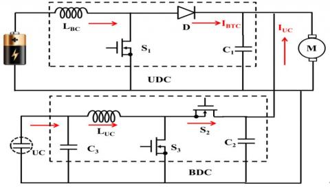
4.2 Mode-II operation
This mode related to slightly more than rated load, so pulses have been generated to switch S1 and S3 that means BDC with boost mode and UDC both are in working condition. Here battery and UC together supplies the power to the motor, which means UC sharing the extra burden on battery.
Figure 4. Converter Mode-II circuit diagram with HESS
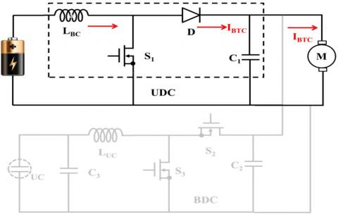
4.3 Mode-III operation
Figure 5. Converter Mode-III circuit diagram with HESS
Pulse signals have been generated to S1 only that means the motor is operating under rated load condition so battery contained power enough to meet the power demand. UDC only operates in this mode and there is no BDC operation because UC assistance not required during this mode of operation so no pulse signals have been generated to switches S2 and S3.
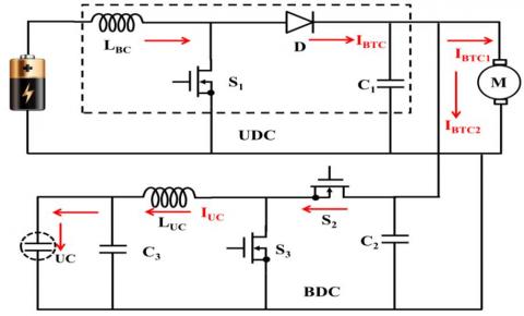
4.4 Mode-IV operation
Figure 6. Converter Mode-IV circuit diagram with HESS
In a mode –IV operation BDC works as a buck converter and as usual UDC works as a boost converter because in this mode motor requires very less power than a battery. Excess power of battery can be utilized to charge the UC during no load or light load condition.
The hybrid controller has been designed by combing MFB with conventional as well as intelligent controllers. The designed hybrid controller controllers the signal of two converters depending upon the speed of the electric motor. It can be categorized into four modes of operation. During mode, one operation pulse signals have been generating to only switch three, in mode two operation pulse signals generates to switch one as well as switch three, in mode three pulse signals generates only to switch one and during mode four operation pulse signals generates to switch one as well as switch two.
Figure 7. Flowchart of the control strategy
(1) During starting of a motor and heavy loaded condition UC supply the power to the load. In this mode, the math function U1 gives signal value 1 and remaining all math functions generates signal 0 because during this period the speed of the motor ≤ 4800 rpm. The converter operates based on all math function generated signals. The converters in operation are the boost converter at the UC end.
(2) When the power demanded by the load is beyond the designed range of the battery output power, UC will assist the battery to deliver power to the motor. In this mode of operation, motor speed is from 4600 rpm to 4800 rpm. Hence MFB generates U1 and U2 pulse signals as 1 and generates U3 and U4 pulse signals as 0. The converters in operation are the boost converter at the battery end and the boost converter at the UC end.
(3) When battery output power matches the desired power of the motor, the battery will only supply the power to the motor. In this mode of operation, the speed of the motor is from 4801 rpm to 4930 rpm. Hence MFB generates a U3 pulse signal as 1 and generates U1, U2 and U4 pulse signals as 0. At this time, only the boost converter at the battery terminal works.
(4) When battery provides more power than the motor need, the extra power will be used to charge the UC. So the power of the battery will flow into both the UC and the motor. In this mode of operation, motor speed is ≥4931 rpm. Hence MFB generates a U4 pulse signal as 1 and generates U1, U2 and U3 pulse signals as 0. According to the converters designed, the boost converter at the battery end and the buck converter at the UC end will work in this scenario.
The converter pulse signal generated to individual switches by the MFB with ANN, Fuzzy, PID and PI controller combination, based on the speed of the electric motor explained with bellow figures 8, 9, and 10.
Figure 8 is related to pulse signals generated to switch S1 based on the speed of an electric motor.
Figure 9 is related to pulse signals generated to switch S2 based on the speed of an electric motor.
Figure 10 is related to pulse signals generated to switch S3 based on the speed of an electric motor.
Figure 8. Pulse signals generated structure to switch ONE present in UDC
Figure 9. Pulse signals generated structure to switch TWO present in BDC
Figure 10. Pulse signals generated structure to switch THREE present in BDC
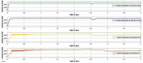
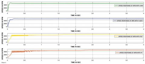
Figure 11. The speed responses of the electric motor during a heavy load condition
6.1 Mode-I results
Figure 11 represents that speed response of electric motor with different hybrid controllers namely MFB plus PI, MFB plus PID, MFB plus Fuzzy and MFB plus ANN during heavy load condition. Before applying load individual hybrid controller has taken different times to reach steady state, in that MFB plus ANN response has taken less time, is 0.15 sec another hand MFB plus PI response has taken more time, is 2.2 sec and remaining two controllers MFB plus PID response has taken 1.7 sec, MFB plus Fuzzy response has taken 0.2sec. At 2.5 sec Heavy load applied on the motor, after that four controllers have taken different time period to reach steady state in that MFB plus ANN response has taken 0.2 sec, MFB plus Fuzzy response has taken 0.25 sec and remaining two controllers responses unable to reach steady state within the stipulated time. After reaching steady state there are no changes in speed curve, it is clear from Figure 11.
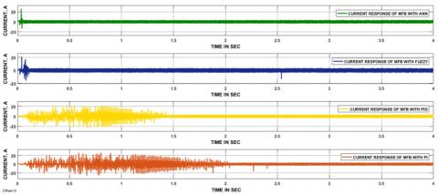
Figure 12. The current responses of the electric motor during a heavy load condition
Figure 13. The pulse signals generated by MFB plus ANN during a heavy load condition
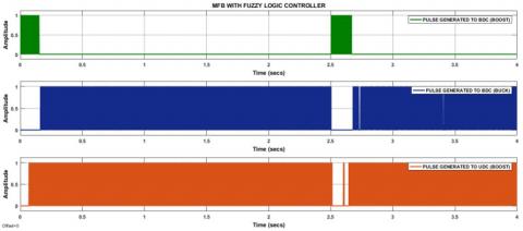
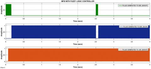
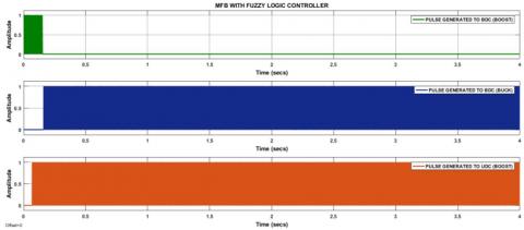
Figure 14. The pulse signals generated by MFB plus Fuzzy during a heavy load condition
Four hybrid controllers’ current responses are presented in order MFB plus PI, MFB plus PID, MFB plus Fuzzy and MFB plus ANN during heavy load condition. Before reaching a steady state of any controller disturbances occurred, after reaching steady state there are no current variations observed from all controllers’ response except MFB plus PI and it is clear from Figure 13. At 2.5 sec heavy load has been applied to the motor during this time huge current variation can observe before reaching steady state. Here MFB with ANN and MFB with Fuzzy responses have reached steady state with 0.25 sec, remain two hybrid controllers unable to reach steady state within the stipulated time.
The controller pulse signal has been generated to BDC as well as UDC by the hybrid MFB plus ANN. During starting period the pulse signals have been generated to only BDC as a boost converter. After reaching steady state pulse signals have been generated to BDC as a buck converter to UC charging and UDC as a boost converter for supply the power to the electric motor as well as UC. At 2.5 sec heavy load applied on the motor, during this period again pulse has been generated to BDC working as boost converter it leads to supply the entire transient power by the UC only. After 0.20 sec motor reached steady state with hybrid controller action, again the pulse signal has been generated to BDC as a buck converter and UDC as a boost converter. Finally, the designed controller responded according to the speed of the electric motor.
The controller pulse signal has been generated to BDC as well as UDC by the hybrid MFB plus Fuzzy. During starting period the pulse signals have been generated to only BDC as a boost converter. After reaching steady state pulse signals have been generated to BDC as a buck converter to UC charging and UDC as a boost converter for supply the power to the electric motor as well as UC. At 2.5 sec heavy load applied on the motor, during this period again pulse has been generated to BDC working as boost converter it leads to supply the entire transient power by the UC only. After 0.25 sec motor reached steady state with hybrid controller action, again the pulse signal has been generated to BDC as a buck converter and UDC as a boost converter. Finally, the designed controller responded according to the speed of the electric motor.
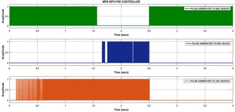
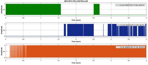
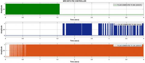
Figure 15. The pulse signals generated by MFB plus PID during a heavy load condition
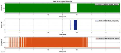
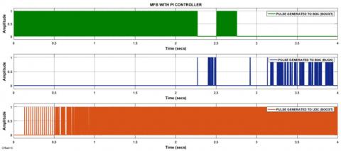
Figure 16. The pulse signals generated by MFB plus PI during a heavy load condition
The controller pulse signal has been generated to BDC as well as UDC by the hybrid MFB plus PID. During starting period the pulse signals have been generated to only BDC as a boost converter. After reaching steady state pulse signals have been generated to BDC as a buck converter to UC charging and UDC as a boost converter for supply the power to the electric motor as well as UC. At 2.5 sec heavy load applied on the motor, during this period again pulse has been generated to BDC working as boost converter it leads to supply the entire transient power by the UC only. During heavy load condition, the controller response doesn’t reach the steady state within a specified time, because of heavy load.
The controller pulse signal has been generated to BDC as well as UDC by the hybrid MFB plus PI. During starting period the pulse signals have been generated to only BDC as a boost converter. After reaching steady state pulse signals have been generated to BDC as a buck converter to UC charging and UDC as a boost converter for supply the power to the electric motor as well as UC. At 2.5 sec heavy load applied on the motor, during this period again pulse has been generated to BDC working as boost converter it leads to supply the entire transient power by the UC only. During heavy load condition, the controller response doesn’t reach the steady state within a specified time, because of heavy load.
6.2 Mode-II results
Figure 17. The speed responses of the electric motor during slightly more than rated load condition
Figure 18. The current responses of the electric motor during slightly more than rated load condition
Figure 19. The pulse signals generated by MFB plus ANN during slightly more than rated load condition
Figure 20. The pulse signals generated by MFB plus Fuzzy during slightly more than rated load condition
Figure 21. The pulse signals generated by MFB plus PID during slightly more than rated load condition
Figure 22. The pulse signals generated by MFB plus PI during slightly more than rated load condition
6.3 Mode-III results
Figure 23. The speed responses of the electric motor during a rated load condition
Figure 24. The current responses of the electric motor during a rated load condition
Figure 25. The pulse signals generated by MFB plus ANN during a rated load condition
Figure 26. The pulse signals generated by MFB plus Fuzzy during a rated load condition
Figure 27. The pulse signals generated by MFB plus PID during a rated load condition
Figure 28. The pulse signals generated by MFB plus PI during a rated load condition
6.4 Mode-IV results
Figure 29. The speed responses of the electric motor during no load condition
Figure 30. The current responses of the electric motor during no load condition
Figure 31. The pulse signals generated by MFB plus ANN during no load condition
Figure 32. The pulse signals generated by MFB plus Fuzzy to BDC as well as UDC during no load condition
Figure 33. The pulse signals generated by MFB plus PID to BDC as well as UDC during no load condition
Figure 34. The pulse signals generated by MFB plus PI to BDC as well as UDC during no load condition
Table 2 shows that comparative analysis of all the controllers in four modes of operation after applying the load on the electric motor. During mode-I operation MFB with ANN and MFB with Fuzzy have taken 0.1 sec and 0.15 sec respectively to reach the steady state after applying the load whereas MFB with PID and MFB with PI have not reached the steady state within a stipulated time. In mode-II operation, slightly more than rated load has been applied and four controllers have taken different times () to reach steady state. 0.003sec, 0.04sec, 0.2sec, and 0.35sec have been taken by MFB with ANN, MFB with Fuzzy, MFB with PID and MFB with PI controllers to reach steady state as the rated load are applied respectively. No load is applied during mode-IV operation.
Table 2. Comparative analysis among the hybrid controllers in four modes of operation based on a load applied
|
Controller |
Time is taken to reach steady state after applying load on the electric motor (sec) |
|||
|
Mode-I |
Mode-II |
Mode-III |
Mode-IV |
|
|
MFB with ANN |
0.1 |
0.09 |
0.003 |
No load applied |
|
MFB with Fuzzy |
0.15 |
0.1 |
0.004 |
No load applied |
|
MFB with PID |
Not settled within given time |
0.4 |
0.2 |
No load applied |
|
MFB with PI |
Not settled within given time |
0.6 |
0.35 |
No load applied |
Table 3. Operation of the converter based on four modes
|
Mode |
UDC |
BDC |
Power flow direction |
|
Mode-I |
Off |
Boost |
UC to Motor |
|
Mode-II |
Boost |
Boost |
UC+Battery to Motor |
|
Mode-III |
Boost |
Off |
Battery to Motor |
|
Mode-IV |
Boost |
Buck |
Battery to Motor+UC |
Table 4. State of math function based on the speed of the motor
|
Condition Based on Speed of the Motor |
State of Math Function |
|
Speed ≤4800 rpm |
U1=1 |
|
4600 rpm≤ Speed ≤ 4800 rpm |
U1=1&U2=1 |
|
4801rpm≤ Speed ≤ 4930 rpm |
U3=1 |
|
Speed ≥ 4931 rpm |
U4=1 |
By designing a hybrid controller the main drawback of HESS powered electric vehicles, that is switching between battery and ultracapacitor can be eliminated. Totally four hybrid controllers have been designed and one good controller has been suggested based on the comparative analysis, for electric motor successful operation. MFB controller was designed with four different math functions depending upon the speed of an electric motor, after that MFB was integrated with different conventional as well as intelligent controller named as PI, PID, Fuzzy, and ANN. All four hybrid controllers have been implemented to the electric vehicle individually for a smooth transition of energy sources in HESS. During heavy load condition, BDC worked as boost converter connected at UC end. In slightly more than rated load condition, BDC, as well as UDC, worked as boost converters one at UC and another one is at the battery end. During rated load condition UDC worked as boost converter has been connected at the battery end. During no-load condition, BDC worked as a buck converter for UC charging and UDC worked as a boost converter connected at the battery end. Further comparison analysis has been made among four hybrid controllers, by considering delay time, rise time, peak time, peak overshoot and settling time after and before applying load on the electric motor. Among all hybrid controllers, MFB plus ANN controller has given satisfactory results by fulfilling all comparative factors. After load applied as well as before load applied comparative analysis were tabulated in the conclusion section. All MATLAB/Simulink results have been plotted and discussed in the simulation results and discussion section.
Table 5. Comparative analysis among hybrid controllers
|
Parameter |
MFB with PI |
MFB with PID |
MFB with Fuzzy logic |
MFB with ANN |
|
Delay time (sec) |
0.15 |
0.1 |
0.05 |
0.003 |
|
Rise time (sec) |
2.1 |
1.3 |
0.1 |
0.09 |
|
Peak time |
2.3 |
1.7 |
0.15 |
0.1 |
|
Settling time (sec) |
2.2 |
1.7 |
0.2 |
0.15 |
|
Maximum peak overshoot (%) |
3 |
2 |
2 |
3 |
Table 6. Comparative analysis among hybrid controllers to reach steady state with and without load
|
Controller |
Time is taken to reach steady state with a load (sec) |
Time is taken to reach steady state at starting (sec) |
|
MFB with PI |
0.4 |
2.2 |
|
MFB with PID |
0.6 |
1.7 |
|
MFB with Fuzzy Logic |
0.1 |
0.2 |
|
MFB with ANN |
0.09 |
0.15 |
Appendix A1. Ultracapacitor parameters
|
Rated capacitance (F) |
5 |
|
Equivalent DC series resistance (Ohms) |
2.1e-3 |
|
Rated voltage (V) |
6 |
|
Number of series capacitors |
6 |
|
Number of parallel capacitors |
1 |
|
Operating temperature (Celsius) |
25 |
Appendix A2. Battery parameters
|
Nominal voltage (V) |
6 |
|
Rated capacity (Ah) |
3.6 |
|
Initial state-of-charge (%) |
99 |
|
Battery response time (s) |
10 |
|
Fully charged voltage (V) |
7.1 |
Appendix A3. Motor parameters
|
Rated voltage(V), power (HP), speed (RPM) |
12,0.268, 5000 |
|
Stator phase resistance Rs (ohm): |
1.16/2 |
|
Stator phase inductance Ls (H) |
194e-6/2 |
|
Back EMF flat area (degrees): |
120 |
|
Inertia, viscous damping, pole pairs, static [ J(kg.m^2) F(N.m.s) p() ]: |
[3.4e-6 1e-7 1] |
Appendix A4. Converter parameters
|
Inductance (H) |
300e-3 |
|
Capacitance (F) |
220e-6 |
|
Resistance(ohms) |
0.1 |
[1] Yin H, Zhou W, Li M, Ma C, Zhao C. (2016). An adaptive fuzzy logic-based energy management strategy on battery/ultracapacitor hybrid electric vehicles. IEEE Transactions on Transportation Electrification 2(3): 300-311. https://doi.org/10.1109/TTE.2016.2552721
[2] Katuri R, Rao GS. (2018). Analysis of math function based controller for a smooth transition between battery and ultracapacitor. Mathematical Modelling of Engineering Problems 5(4): 386-394. https://doi.org/10.18280/mmep.050416
[3] Katuri R, Gorantla SR. (2018). Math function based controller applied to electric/hybrid electric vehicle. Modeling, Measurement and Control A 91(1): 15-21. https://doi.org/10.18280/mmc_a.910103
[4] Shen J, Khaligh A. (2015). A supervisory energy management control strategy in a battery/ultracapacitor hybrid energy storage system. IEEE Transactions on Transportation Electrification 1(3): 223-231. https://doi.org/10.1109/TTE.2015.2464690
[5] Trovao JPF, Santos VD, Antunes CH, Pereirinha PG, Jorge HM. (2015). A real-time energy management architecture for multisource electric vehicles. IEEE Trans. Industrial Electronics 62(5): 3223-3233. https://doi.org/10.1109/TIE.2014.2376883
[6] Dusmez S, Khaligh A. (2014). A supervisory power-splitting approach for a new ultracapacitor–battery vehicle deploying two propulsion machines. IEEE Transactions on Industrial Informatics 10(3): 1960-1971. https://doi.org/10.1109/TII.2014.2299237
[7] Torreglosa JP, Garcia P, Fernandez LM, Jurado F. (2014). Predictive control for the energy management of a fuel-cell–battery–supercapacitor tramway. IEEE Transactions on Industrial Informatics 10(1): 276-285. https://doi.org/10.1109/TII.2013.2245140
[8] Mirzaei A, Jusoh A, Salam Z, Adib E, Farzanehfard H. (2011). A novel soft switching bidirectional coupled inductor buck-boost converter for battery discharging-charging. In Applied Power Electronics Colloquium (IAPEC), 2011 IEEE, pp. 195-199. https://doi.org/10.1109/IAPEC.2011.5779840
[9] Cao J, Emadi A. (2012). A new battery/ultracapacitor hybrid energy storage system for electric, hybrid, and plug-in hybrid electric vehicles. IEEE Transactions on Power Electronics 27(1): 122-132. https://doi.org/10.1109/TPEL.2011.2151206
[10] Camara MB, Gualous H, Gustin F, Berthon A, Dakyo B. (2010). DC/DC converter design for supercapacitor and battery power management in hybrid vehicle applications—Polynomial control strategy. IEEE Transactions on Industrial Electronics 57(2): 587-597. https://doi.org/10.1109/TIE.2009.2025283
[11] Xiang C, Wang Y, Hu S, Wang W. (2014). A new topology and control strategy for a hybrid battery-ultracapacitor energy storage system. Energies 7(5): 2874-2896. https://doi.org/10.3390/en7052874
[12] Tie SF, Tan CW. (2013). A review of energy sources and energy management system in electric vehicles. Renewable and Sustainable Energy Reviews 20: 82-102. https://doi.org/10.1016/j.rser.2012.11.077
[13] Ren G, Ma G, Cong N. (2015). Review of electrical energy storage system for vehicular applications. Renewable and Sustainable Energy Reviews 41: 225-236. https://doi.org/10.1016/j.rser.2014.08.003
[14] Kuperman A, Aharon I. (2011). Battery–ultracapacitor hybrids for pulsed current loads: A review. Renewable and Sustainable Energy Reviews 15(2): 981-992. https://doi.org/10.1016/j.rser.2010.11.010