Dillip K. Sahoo* | Bhulok S. Mohanty | Amal P. Maalika Veetil
© 2020 IIETA. This article is published by IIETA and is licensed under the CC BY 4.0 license (http://creativecommons.org/licenses/by/4.0/).
OPEN ACCESS
The present experimental work focused for evaluating the bond strength and flash mass on deposition of Aluminum 6063 over IS 2062 low carbon steel by friction surfacing using different design of mechtrode face. Five design of mechtrode were chosen, named as MF1, MF2, MF3, MF4 and MF5 for carrying out the friction surfacing with different parametric combinations. Study had shown that the amount of flash mass produced by mechtrode was increased by increasing the mechtrode face contact area. Low flash mass (about 28% of the deposited mass) and high push off strength (79.4 MPa) were noticed in MF5 mechtrode samples. The micro hardness profile at the coating interface highlighted a highest increase of 18.6% hardness at specimen obtained from MF5 mechtrode in comparison with received mechtrode material. The bending test revealed that at high rotational speed (3000 rpm) and high axial force (6 kN) could increase the adhesive bonding at the interface zone. Cross section of coatings obtained from various mechtrode face had shown good bonding adherence quality and high mechanical interlocking which were confirmed by using high amplification FE- SEM images and the absence of aluminium ferrite (AlFe2O4) at deposition interface were authenticated by XRD analysis.
friction surfacing, mechtrode face, micro hardness, ram tensile, bending, FE-SEM, XRD
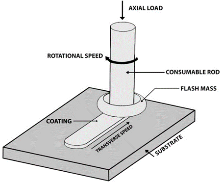
Friction surfacing is a friction based solid state layer process which uses the frictional energy dispersed among the operation and induces a molten state metal without the participation of any extraneous heat source and generates high strength and high-quality linkages with fewer deformations in an extensive variety of material lengths and thickness. In the process of Friction surfacing, the substrate plate is fixed in between the two fastened plates. The rotating consumable rod known as mechtrode moves lengthways on the substrate material with firm transverse speed or travel speed and at the interface of two materials, heat is engendered as a result of frictional effect. The principle of friction surfacing process was displayed in Figure 1. Depending upon the comparative strengths of the tool and substrate material and accumulation to the achieved temperature, frictional plastic deformation may undergo only at tool material, base material or both tool and substrate material. This deformation leads to coating of the consumable rod on the substrate surface or alloying near the base material surface leading to a change in the surface properties of the base material. The physical, mechanical properties and bond quality mainly rely on numerous process parameters such as, rotational speed of the consumable rod (rpm), vertical axial load on the substrate and transverse speed of the substrate material (mm/s). Hence, they were referred to as fundamental process parameters. The quality of deposition, width, thickness, surface finish and the intermetallic bonding quality depends greatly on the selection of process parameter combination.
The experimental work Rafi et al. [1] related to the effect of transverse speed and surface bonding characteristics between AISI 310 Austenitic stainless steel and Low Carbon Steel and found good bonding strength coating at higher transverse speed. Rao et al. [2] did analysis of the thermal profiles for different sets of consumable rod/substrates (tool steel/steel; copper/steel and copper/copper) during friction surfacing through infrared thermography and found different stages of plastic deformation with relevance to temperature and indicated the occurrence of metallurgically guaranteed coating when flow stress of the plasticized material was equal to the localized stress developed as a result of axial loading. In their research work, Gandra et al. [3] did the performance analysis of friction surfaced mild steel over mild steel and found the axial load applied on mechtrode having a great influence on improving the joining efficiency of the coating. Janakiraman et al. [4] did the corrosion evaluation of AISI 316L stainless steel coatings made using friction surfacing and manual metal arc welding processes and saw a superior high pitting corrosion resistance coating exhibited in the friction surfacing process. Singh et al. [5] have done analysis of the coating geometry, interfacial bond characteristics and the mechanical properties of coatings between aluminium and mild steel and found the traverse speed having a great influence on them. Gandra et al. [6] did experimental work on friction surfacing of AA 6082-T6 over AA 2024-T3 substrates with focus on the process parameters and observed the lower combination of travel speed and rotational speed attributes making a higher coating thickness and width while. Bonding at coating edges were worse at a higher travel speed. In their experimental work Kumar et al. [7] showed the viability of deposition of commercial copper on mild steel by friction surfacing and suggested good copper deposition can be obtained through the rough milling with the influence of the roughness which plays a vital role in the formation of good coating. Barnabas [8] obtained the parameters for optimizing the friction surfacing in which the optimizing of process parameters helped achievement of sufficient bond strength and good coating integrity of deposit. Govardhan et al. [9] did investigation on the characterization study of the bonding quality between stainless steel and carbon steel considering the parameters of friction surfacing techniques, bonding mechanism, and different combinations of materials. They have also discussed the effect of process parameters on the responses like coating width, height, surface roughness, tensile strength, shear strength of the coating. Fitseva et al. [10] did investigation on the bonding characteristics and deposition behavior of titanium over titanium at various rotational speeds based on the respective process parameters. In their investigation, they suggested that the flash formation during the friction surfacing process could be controlled by using appropriate rotational and transverse speed of the consumable rod. In their experimental work Kumar et al. [11] made a study of the pitting corrosion resistance of the friction surfaced samples between austenitic stainless steel AISI 304 over low alloy steel substrate and found Pitting corrosion of surfaced coatings as much lower than that of mechtrode material and superior to that of substrate material. Stegmueller et al. [12] worked on the effect of inductive heating during the friction surfacing of stainless steel over aluminium substrate and observed an increase in that flash mass produced by the consumable rod at the coating interface as a result of an increase in the rotational speed of the consumable rod during the deposition. In their work Madhu et al. [13] produced a temperature model of mechtrode using the finite element method during the friction surfacing between aluminium 6061 over stainless steel. They also simulated the temperature field of the consumable rod. Fitsev et al. [14] studied the influence of rotational speed on friction surfaced deposition of Ti-6Al-4V coatings and evaluated the material flow and micro structure of friction surfaced Kumar et al. [15] inspected the relation between the process parameters of friction surfacing and the coating geometry of Aluminium alloy 6063 coated over IS2062 Mild steel and observed a decrease in the thickness of the coating when coating width increased. In addition, the width and thickness of the coatings were higher at low and high torques. In their study, Michael et al. [16] found the employment of inductive heating on friction surfacing stainless steel over aluminium substrates utilizing a special flash-reducing tool to improve process efficiency and resulted in an increased consumption of the coating material and improved bond strength of coating. Kedar et al. [17] did experimental work on friction surfacing of aluminum 6351 T6 coated on the carbon steel substrate using various diameters of consumable rod. Temperatures were also measured using data logger on the advancing and retreating sides of the coating. Stefanie et al. [18] made experimental studies on the micro structural features and dynamic recrystallization of Nickel based alloy 625 by friction surfacing and found a palpable effect the particle nucleation and development were significantly by localized shear stress and residual strain developed during the process. The coatings exhibited a fully recrystallized microstructure with equiaxed grains (0.5 to 12 μm) and a low degree of grain average misorientation. Nixon et al. [19] studied the characterization of coating of AISI316 stainless steel over EN24 medium carbon steel substrate and observed a reduction in the depth of the coating with increase in the coating width. No carbide particles were seen at the coating interface which influences the effectiveness of good bonding. Carlos et al. [20] has assess the process parametric combination on double layer deposition between aluminium 6351 and aluminium 5052 by friction surfacing process. Silverio et al. [21] address the performance and geometrical analysis on deposition between AA5083-H112over AA2024-T3 by friction surfacing process and found that heat generation at interface and plastic deformation enhance the dynamic recrystallization of the consumable rod. Li et al. [22] studied the microstructural features on deposition of aluminium alloy 5983 over DH36 steel by friction surfacing and found the elemental diffusion of Fe and presence of intermetallic compounds of FeAl3 at coating interface.
Figure 1. Principle of friction surfacing
Bararpour et al. [23] analysed the thermo mechanical performance through ABACUS software on cladding of AA5083 over AA5052 by Friction surfacing and suggested that grain structure has not greatly influenced by strain energy present during coating.
This work is associated to evaluate the flash mass and bond strength of obtained friction surfacing samples of aluminium and carbon steel by using five different design of mechtrode face. Coating mass (Mc), consumption feed rate (τb), flash mass (Mf) and mass per coated length were analysed for all obtained samples with different parametric combinations. A successful high strength coating of Aluminium 6063 over IS 2062 low carbon steel offers a great number of industrial applications and stringent use environments.
2.1 Materials
Low Carbon Steel with 8 mm thickness was used as the substrate plate and machined to dimensions of 100 mm width and 150 mm length. AA6063 Aluminium alloy with 18 mm diameter and 100 mm length used as mechtrode rod. The chemical compositions of Low Carbon Steel and AA6063 Aluminium Alloy are displayed in Table 1, Table 2 respectively.
Table 1. Chemicial composition of IS2062 low carbon steel
|
Material |
C |
Mn |
P |
S |
Si |
Cr |
Ni |
Fe |
|
% of Composition |
0.17 |
0.65 |
0.026 |
0.01 |
0.20 |
0.01 |
0.01 |
Balance |
Table 2. Chemical composition of AA 6063 aluminium alloy
|
Material |
Mg |
Si |
Cr |
Mn |
Ti |
Zn |
Fe |
Al |
|
% of Composition |
0.55 |
0.4 |
0.1 |
0.1 |
0.1 |
0.1 |
0.35 |
Balance |
Table 3. Mechanical properties of low carbon steel and aluminium
|
Material |
Yield stress (Mpa) |
Ultimate strength (Mpa) |
Hardness (HV) |
|
Low carbon steel(IS 2062) |
250 |
410 |
266 |
|
Aluminium Alloy (6063) |
170 |
241 |
75 |
2.1.1 Substrate plate
Before proceeding to do the friction surfacing process, the surface of low carbon steel substrate was made to undergo a machining operation by milling to uproot a thin layer of thickness (usually 0.5 mm) to remove the oxidized material surface and confirm a flat and even surface to make close contact between the substrate and mechtrode at interface region. Both substrate plate and mechtrode rod were cleaned thoroughly by acetone solution for avating contamination during the process. The major mechanical properties of both material combination are shown in Table 3.
2.1.2 Mechtrode rod
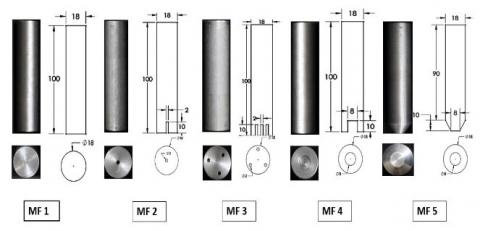
Five different types of Mechtrode Face (MF) were prepared for conducting friction surfacing named as MF1, MF2, MF3, MF4 and MF5 respectively. MF1 had the conventional flat surface at the bottom, MF2 had a centre hole of 2 mm diameter with 10 mm depth, MF3 had 3 hole of 2 mm diameter (triangularly arranged) with 10 mm internal depth, MF4 had a hole of 8 mm diameter with 10 mm internal depth while MF5 had a tapered face of 8 mm diameter with 10 mm height. The mechtrode length was kept constant of 100 mm overall length with 18 mm diameter. All mechtrode went through various machining operations to get the desired shape. The obtained mechtrode rod was displayed in Figure 2. A different shape of the mechtrode face was taken after a study of findings from literature. Making the mechtrode in different shape was seen to influence mainly the bonded width, thickness and reduction of flash mass formation.
The contact area of different mechtrode face has been calculated and displayed in Table 4. It has been seen that the MF5 mechtrode has the minimum and MF1 has the maximum contact area on substrate plate, which has a great influence on consumption of mechtrode material during the process.
Table 4. Friction surfacing parameters
|
Axial Load (kN) |
Rotational speed(rpm) |
Transverse speed(mm/min) |
|
4,5,6 |
1500,2000,2500,3000 |
150 |
2.2 Experimental process and parameters
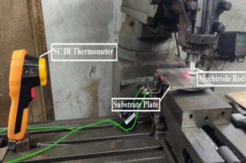
The experimental process was directed in a convention friction surfacing machine with a single line deposition in a length of about 100 mm. The machine had maximum power at spindle 1000 mm/min 20 KW. The selection of materials for the FS experiments was done on the basis of the requirement of developing a thick crack free coating with high corrosion resistance and good heat treasfer rate. Consideration of these properties helped in getting the abling to do coating for the enhancement of the life of the substrate.
Figure 2. Dimension and shape of the five different mechtrode
Figure 3. Friction surfacing machine set up
Parameter assortment was based on the trials from former experiments and literature survey. All through friction surfacing, the substrate plates were fibbed down over a planar rigid anvil and were clamped similar to the travel of consumable rod. Figure 3 shows the schematic diagram of the experimental arrangement.
3.1 Characterization of coatings
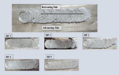
The characterization of coating represents a visual inspection and/or by using a small magnification tool of the deposits obtained after the processing of the mechtrode materials. This allowed identification of the important features such as roughness, coating length, width and thickness in function of axial force, rotational speed and transverse speed. Figure 4 presents the deposits performed by AA6063 Aluminium alloy over Low Carbon Steel using five different shape of mechtrode. Figure 4 shows the deposition characteristics after friction surfacing in both advancing and retreating side along the motion direction of the transverse speed and rotational speed of the consumable rod. For each coating display in Figure 4, shown the (i) surface roughness which was highly influenced by transverse speed (ii) characteristics of coating (length, width & thickness), which was continuous and homogeneous and depending on the process parameters of friction surfacing. Figure 4 shows the deposit obtained from MF5 mechtrode having continuous and homogeneous throughout the length. This was due to the optimum area contact between mechtrode and substrate during dwell phase leading to the formation of a limited flash and continuous dynamic recrystallization during deposition phase.
The detailed analysis on the consumption of mechtrode material during the FS process was done and displayed in Table 5. Highest mechtrode length (around 41.38 mm) was consumed for MF1 mechtrode, similarly for MF5 mechtrode, lowest consumption of mechtrode length was observed among other mechtrodes.
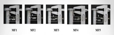
The shape and the width of the flash formation at mechtrode face after friction surfacing were measured by Vernier caliper and displayed in Figure 5. The width of flash was found to be around 6.3 ± 0.02 mm (maximum value) in the case of MF1 and around 2.7±0.02 mm (minimum value) in the case of MF5. Higher flash width at mechtrode face indicates less mass transfer during coating similarly mechtrode face having a smaller flash width indicate high mass transfer during process resulted good and uniform deposition at substrate plate. Michael et al. [16].
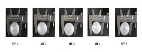
Figure 6 shows the diameter measurement of tool face after friction surfacing. The highest diameter (33.7±0.02 mm) was obtained in MF2 mechtrode and the minimum diameter (28.7 ±0.02 mm) has from the MF5 mechtrode. The diameter of the mechtrode face had a marginal influence on formation of flash mass. However, a lower diameter of mechtrode face showed more consumable mass deposit at the substrate during process and as a result, produced less flash mass at the mechtrode.
Figure 4. Deposit of Aluminium alloy on low carbon steel by five different mechtrode shape
Table 5. Consumption of mechtrode length during friction surfacing
|
Mechtrode Face |
Mechtrode length (mm) |
FS machine tool holding length (mm) |
Available mechtrode length for FS (mm) |
Mechtrode Contact area (m2) |
Consumed mechtrode length during FS (mm) |
Available mechtrode length after FS (mm) |
|
MF1 |
100 |
30 |
70 |
2.54×10^-4 |
41.38 |
28.62 |
|
MF2 |
100 |
30 |
70 |
2.51×10^-4 |
38.02 |
31.98 |
|
MF3 |
100 |
30 |
70 |
2.45×10^-4 |
35.32 |
34.68 |
|
MF4 |
100 |
30 |
70 |
2.04×10^-4 |
32.16 |
37.84 |
|
MF5 |
100 |
30 |
70 |
5×10^-5 |
30.52 |
39.48 |
Figure 5. Measurement of flash width of mechtrode after friction surfacing
Figure 6. Measurement of mechtrode face after friction surfacing
A comparison of the relationship between several input and output parameters of friction surfacing done by using different mechtrode shape is displayed in Figures7-13. Parameters like axial force, mechtrode rotational speed and transverse speed have been considered as input parameters and parameters like Coating thickness (Ct), Coating width (Cw), Coating mass (Mc), Consumption feed rate (τb), Flash masses (Mf) and mass per Coated Length are taken as output parameters.
Figure 7. The effect of rotational speed on the coating Width (Cw)
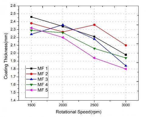
The influence of rotational speed on coating width and thickness is shown in Figures 7 and 8 respectively. An increase in the coating width was seen and a decrease in the coating thickness with increase in the rotational speed. However, the coating width obtained was maximum at the intermediate level of the rotational speed (2500 rpm) decreasing towards higher level rotational speed (3000 rpm) shown in Figure 7. The coating width obtained from MF1 mechtrode varied from 17.85 mm to 19.12 mm is while the maximum coating width 19.62mm was obtained from MF4 Mechtrode at a higher axial force. Figure 8 shows the effect of the rotational speed on coating thickness. A gradual decrease in coating thickness with increase in the rotational speed was seen. The thickness varied from 2.46 mm to 1.98 mm in MF1 mechtrode and 2.32 to 1.82 mm in MF5 mechtrode at different rotational speed. The formation of flash mass at the mechtrode face had a marginal effect in the development of coating thickness and width during friction Surfacing.
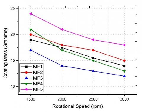
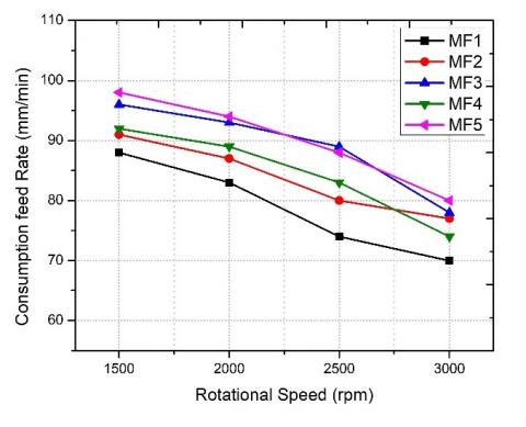
The effect of rotational speed on coating mass on different mechtrodes is shown in Figure 9. The result showed the coating mass deposition as higher in MF5 mechtrode compared to the sample obtained from other mechtrode. A decrease in the coated mass following an increase in the rotational speed with all the values of the axial force was observed. Figure 10 shows the relationship between the consumption feed rate with rotational speed and the result revealed a decrease in the consumption feed rate of the coating rod while increasing the rotational speed. A high rate of rod consumption feed rate provides uniform and continuous coating. The maximum consumption feed rate (τb) seen at MF5 mechtrode sample which is around 96 mm/min at maximum axial force with minimum rotational speed, and reduced to 23% to a minimum value of 78 mm/min by doubling the rotational speed at minimum axial force.
Figure 8. The effect of rotational speed on the coating thickness (Ct)
Figure 9. The effect of rotational speed on the coating mass (Mc)
Figure 10. The effect of rotational speed on consumption feed rate (τb)
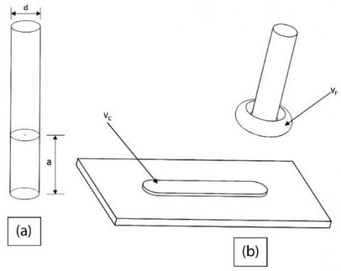
Estimation of the consumed volume of the coating rod, V, in the process helped calculation of the establishment of the flash mass, given by:
V = a xd2x πx 0.25 (1)
where, ‘d’ is the diameter of the coating rod and ‘a’ is the burn-off length, which equates to the shortening of the coating rod, as shown in Figure 11.
Figure 11. Shortening of rotating rod (a) before and (b) after friction surfacing process
The volume of the coating (Vc) is
Vc = Cm/ρ (2)
where, ρ is the density of the coating material and Cm is the mass of the coating. By the deduction of the previously calculated volumes, the volume of the flash is determined, as follows:
VF = V − Vc = a x d2x πx 0.25− Cm/ρ (3)
The flash mass may be calculated by using
Mf = VF x ρ = a x d2x πx 0.25xρ–Cm (4)
Figure 12 shows increase in the formed flash mass per coating mass with an increase in the rotational speed. As per the mathematical computation using Eq. (4). The formed flash mass was seen nearly equal to the coating mass at a low combination of rotational speed and axial force (1500 rpm, 4 kN) however, at high combination (3000 rpm, 6 kN) the flash mass is 1.5 times more than the coating mass. Figure 12 shows a decrease in the flash mass per coating mass around 6.8%, 5.3%, 4.4%, 3.8% & 2.7% at low combination of rotational speed with axial force and about 9.6%, 8.2 %, 7.8%, 6.8% & 4.4 % at high combinations of rotational speed and axial force in the case of MF1, MF2, MF3, MF4 & MF5 mechtrode respectively. Figure 13 exhibits the formation of flash mass as inversely proportional to the deposition of coating mass per given coating length in all the ranges of the rotational speed and axial force. If the flash mass is more at high rotational speed, the coating mass per applied coating length decreases, as can be seen in Figure 13. The deposition of coating mass per applied coating length has a great influence on the formation of flash mass during friction surfacing process.
Figure 12. The effect of rotational speed on the flash mass/coating mass
Figure 13. The effect of rotational speed on mass per coated length
3.2 NC-IR infrared thermometer
In the friction surfacing process, the development of frictional heat between mechtrode and substrate face is the key factor for the successful formation of coating. A Non-contact type IR thermometer was used for the measurement of the interface temperature between the consumable rod and the substrate. The thermal profile of different mechtrode face displayed in Figure 14, provides a temperature time plot starting from dwell period to the end of the deposition phase. Figure 14. shows the occurrence of a rapid increase in temperature (adiabatic heating) during dwell phase and temperature became steady during the deposition phase. Before the start of the deposition phase, there was a slight decrease in temperature when the transverse speed started to apply. This was due to the deposition of visco plastic materials from the mechtrode face to the substrate plate. Again, there was an increase in temperature as a result of the generation of high frictional heat by molecular diffusion during the deposition. The maximum peak temperatures recorded were 468℃, 456℃, 444℃, 434℃ and 421℃ for different mechtrode face MF1, MF2, MF3, MF4 & MF5 respectively. The high maximum temperature led to formation of brittle intermetallic layer at the interface while low maximum temperature with steady state enhanced the molecular transformation during process. The axial force and rotational speed were seen having a great influence on the temperature formation at the interface. A higher range of its combination (6 kN, 3000 rpm) produced a higher peak temperature compared to its lower range of combination (4 kN, 1500 rpm).
Figure 14. Temperature profile obtained from IR thermometer for different mechtrode shape
3.3 Mechanical testing
3.3.1 Vickers micro hardness test
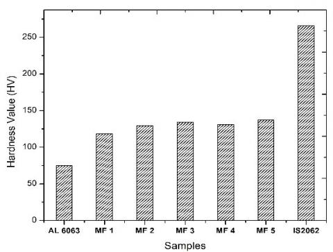
The Vickers hardness method is the most suitable for low test loads and applicable for any kind of surface treatment process. Before conducting the test, the samples obtained were cross sectioned in longitudinally and transversally directions and polished by an automatic grinding or polishing machine. Indentations were made at different points along the coating as shown in Figure 15(a) for the measurement of the micro hardness of the coating samples. The indentations were placed at a direction perpendicular to the interface of the coating and the substrate with a load of 1kgf and a period of 18 seconds dwell time. The hardness values measured for the coating samples obtained from different mechtrode shape are presented in Figure 15(b). A higher hardness values was achieved at the coating interface compared to the consumable aluminium material (75 HV). The average hardness values of MF1, MF2, MF3, MF4 and MF5 mechtrode were seen as 118 HV, 129 HV, 134 HV, 131 HV and 137 HV respectively. Hardness comparison between consumable aluminium rod, IS 2062 substrate plate and various samples obtained from different mechtrode face was displayed in Figure 16. These deviations can be ascribed to better micro structure formation and molecular interlocking at interface. It is a significant aspect for the application that tends to reduce the wear resistance. The increase in hardness value at the interface has been strongly influenced by the rotational speed.
Figure 15. (a) Indentation marking in micro hardness machine (b) hardness distribution of different specimens
Figure 16. Comparison of hardness value between mechtrode, substrate and samples obtained from different mechtrode face
3.3.2 Ram tensile test
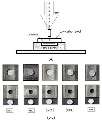
The ram tensile test was performed to understand the interfacial bonding strength between the substrate material shown in Figure 17. For carrying out this test, The coating material was made into a circular area from the substrate shaping an inner circle without coating material and preserving the outer circular area to appear as an annular space consisting of both substrate and coating. The outer circle coating was constructed to enable support to the substrate on a fixture to such a degree that only a part of the inner circular area in the annular space was exposed to axial loading on that area. The test was carried out on a 100 KN INSTRON UTM testing machine by applying a continuous load until the bond failed. Figure 18 shows the influence of axial force on bonding strength of coating samples obtained from various mechtrodes. It has been observed that the bonding strength varies positively towards the higher axial force. The achievement of a high bonding strength (79.4 Mpa) in MF5 mechtrode and low bonding strength (64.25 Mpa) for MF2 mechtrode were seen at axial force of 6 KN. The development of bonding strength for all samples were arranged in following sequence.
MF5> MF3> MF4>MF1> MF2
Figure 17. Ram tensile test (a) experimental set up (b) sample before ram tensile (c) sample after ram tensile test
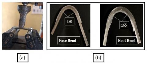
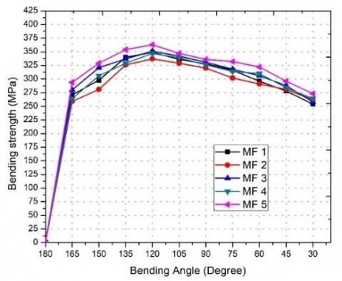
3.3.3 Bending test
The samples obtained through use of different mechtrode faces of friction surfacing were selected for the face and root bend test with various parametrical combinations. The preparation of test samples and procedures was maintained according to IS 1599 (2012) standards and are shown in Figure 19. Figure 20 displayed the development of bending stress with respect to bending angle for sample obtained from different mechtrode face. The sample did not show any peeling or crack in both face and root bending test and maximum bending strength were achieved at a value of 349 MPa, 337MPa, 351MPa, 347MPa, 363MPa at 120o bend angle of samples from mechtrode face MF1, MF2, MF3, MF4 and MF5 respectively. The achievement of a high bending strength at MF5 mechtrode face and a low bending strength at MF2 mechtrode face were seen.
Figure 18. Interface bonding strength from different mechtrode face
Figure 19. Bending test (a) experimental set up (b) samples after bend test
Figure 20. Bending stress vs bending angle of different mechtrode
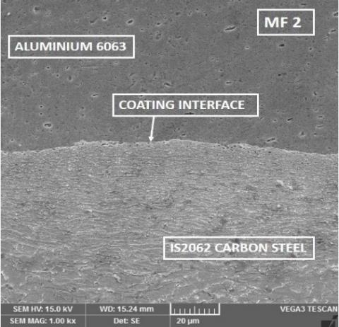
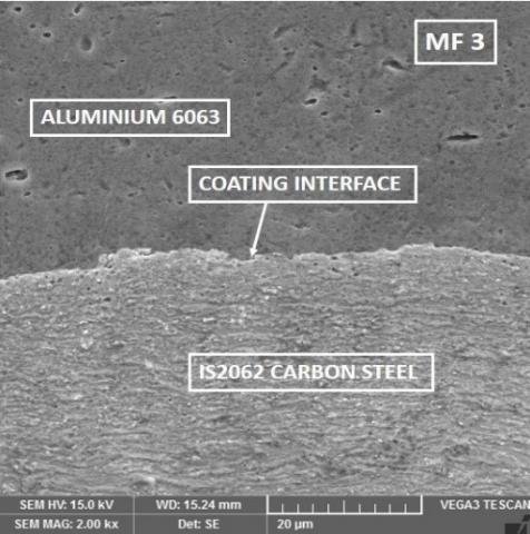
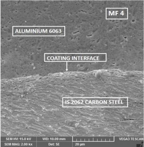
3.4 Field emission scanning electron microscopy (FE-SEM)
FE-SEM images were taken at the specimen obtained from deposition of aluminium over IS2062 carbon steel using all 5 mechtrode face and displayed at Figure 21. COXEM PX 200 optical microscope was used for taking the images and the specimens were sectioned with dimensions of 5x5 mm and were polished metallurgically and engraved with Nital solution (90% Ethanol + 10% Nitric acid). The result shows that the formation of heat during friction surfacing, led to the specimens getting mixed and the active recrystallization occurred which leads to the mixture of chemical composition like cobalt, chromium, nickel and other compounds at the interface. The active recrystallization helped determination of the hardness of the coating by quenching which depended on the carbon content, alloying composition and cooling rate. Gandra et al. [24]. The compositional profile across the interface was analysed and a good level of mixing of species on the either side of the interface was found at specimen obtained from MF5 mechtrode and a minimum level of intermixing of species at interface has seen at sample from MF1 mechtrode which was clearly portrayed at Figure 21. The interface surface has occasional micro fillings on the flat surface and the interface was macroscopically smooth, without creating any profiles during the process of friction surfacing. Generation of chemically active surfaces was confirmed by the formation of unevenness at the interface, where a solid state joining mechanism was formed by the diffusion principle and hence atomic binding was activated [15].
Figure 21. Microstructural view at coating interface of sample obtained from various mechtrode face. Process parameters (5 kN, 2500 rpm, 150 mm/Min)
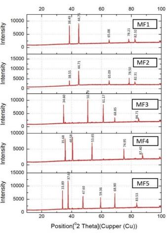
3.5 XRD analysis
The X-ray diffraction analysis of the specimen obtained by deposition of aluminium over IS2062 carbon steel were conducted and displayed in Figure 22. In case of specimen obtained from MF5 mechtrode the most intense peak of aluminium was observed at 2θ values at 32.19, 36.78, which matches well with standard pattern. From coating obtained from MF1, MF2, MF3 and MF4 mechtrode, Several peaks of Al content was observed at 2θ values from 35o to 75o which corresponds to the substrate IS2062 carbon steel, revealing the good bonding of aluminium over the carbon steel substrate.The result confirmed the nonexistence of aluminium ferrite (AlFe2O4) and existence of Al-Mg compounds at their interface in all the specimen probably due to steady temperature concentration and rapid cooling.
Figure 22. XRD analysis of specimen obtained from different mechtrode
Number of specimens were obtained on deposition of Aluminium over IS 2062 carbon steel by Friction surfacing using different mechtrode face. The bond strength and effectiveness of process parameters on flash mass formation was evaluated. The succeeding presumption were made from the experimental works.
The experimental and testing work was supported by, NIT Warangal, Central Leather Research Institute, Chennai.
[1] Rafi, K.H., Ram, J.G.D., Phanikumar, G., Kalvala, P. (2010). Friction surfacing of austenitic stainless steel on low carbon steel: Studies on the effects of traverse speed. Proceedings of the World Congress on Engineering 2010 vol. II, WCE, London, U.K.
[2] Reddy, M.G., Prasad, S.K., Rao, K.S., Mohandas, T. (2011). Friction surfacing of titanium alloy with aluminium metal matrix composite. Surface Engineering, 27(2): 92-98. https://doi.org/10.1179/174329409X451128
[3] Gandra, J., Miranda, R.M., Vilac, P. (2012). Performance analysis of friction surfacing. Journal of Materials Processing Technology, 212(8): 1676-1686. https://doi.org/10.1016/j.jmatprotec.2012.03.013
[4] Janakiraman, S., Udaya Bhat, K. (2012). Formation of composite surface during friction surfacing of steel with Aluminium. Advances in Tribology, 2012: 1-5. https://doi.org/10.1155/2012/614278
[5] Singh, S.J., Prakash, M., Laxminarayana, P. (2013). Characterization of aluminum over mild steel by friction surface processing. International Journal of Advanced Trends in Computer Science and Engineering, 2(6): 61-63.
[6] Gandra, J., Pereira, D., Miranda, R.M., Vilaca, P. (2013). Influence of process parameters in the friction surfacing of AA 6082-T6 over AA 2024-T3. Procedia CIRP, 7: 341-346. https://doi.org/10.1016/j.procir.2013.05.058
[7] Jujare, T., Kumar, K., Kailas, S.V., Bhat, U.K. (2014). Friction surfacing of mild steel by copper- A feasibility study. Procedia Materials Science, 5: 1300-1307. https://doi.org/10.1016/j.mspro.2014.07.445
[8] Barnabas, G. (2014). Parameters Optimization in Friction Surfacing. Chemical and Materials Engineering, 2(6): 127-136. https://doi.org/10.13189/cme.2014.020601
[9] Govardhan, D., Sammaiah, K., Murti, K.G.K., Reddy, M.G. (2015). Evaluation of bond quality for stainless steel-carbon steel friction surfaced deposits. Materials Today: Proceedings, 2(4-5): 3511-3519. https://doi.org/10.1016/j.matpr.2015.07.327
[10] Fitseva, V., Krohn, H., Hanke, S., Dos Santos, J.F. (2015). Friction surfacing of Ti- 6Al-4V: Process characteristics and deposition behaviour at various rotational speeds. Surface & Coatings Technology, 278: 56-63. https://doi.org/10.1016/j.surfcoat.2015.07.039
[11] Singh, A.K., Reddy, M.G., Rao, S.K. (2015). Pitting corrosion resistance and bond strength of stainless-steel overlay by friction surfacing on high strength low alloy steel. Defence Technology, 11(3): 299-307. https://doi.org/10.1016/j.dt.2015.06.002
[12] Stegmueller, M.J.R., Schindele, P., Grant, R.J. (2015). Inductive heating effects on friction surfacing of stainless steel onto an aluminium substrate. Journal of Materials Processing Technology, 216: 430-439. https://doi.org/10.1016/j.jmatprotec.2014.10.013
[13] Madhu, S., Balasubramanian, M., Rathesh, Sivakesan. (2016). Finite difference modeling on the temperature field of aluminium and low carbon steel in friction surfacing. ARPN Journal of Engineering and Applied Sciences, 11(16): 10065-10071.
[14] Fitseva, V., Hanke, S., dos Santos, J.F. (2016). Influence of rotational speed on process characteristics, material flow and micro structure evolution in friction surfacing of TI-6AL-4V. Materials and Manufacturing Processes, 32(5): 557-563. https://doi.org/10.1080/10426914.2016.1257799.
[15] Kumar. R., Chattopadhyaya, S., Ghosh, A., Krolczyk, G.M., Vilaca, P., Kumar, R., Srivastava, M., Shariq, M., Tripathi, R. (2017). Characterization of friction surfaced coatings of AISI 316 tool over high speed steel substrate. Transactions of FAMENA, 41(2): 61-76. https://doi.org/10.21278/TOF.41206
[16] Stegmüller, M.J.R., Grant, R.J., Schindele, P. (2017). Improvements in the process efficiency and bond strength when friction surfacing stainless steel onto aluminium substrates. Journal of Materials: Design and Applications. https://doi.org/10.1177/1464420717701494
[17] Badheka, K., Badheka, V. (2017). Friction surfacing of aluminium on steel: An experimental approach. Materials Today: Proceedings, 4(9): 9937-9941. https://doi.org/10.1016/j.matpr.2017.06.297
[18] Hanke, S., Sena, I., Coelho, R.S., dos Santos, J.F. (2017). Microstructural features of dynamic recrystallization in alloy 625 friction surfacing coatings. Materials and Manufacturing Processes, 33(3): 270-276. https://doi.org/10.1080/10426914.2017.129194
[19] Nixon, G.S.R., Mohanty, B.S., Bhaskar, G.B. (2017). Effect of process parameters on physical measurements of AISI316 stainless steel coating on EN24 in friction surfacing. Materials and Manufacturing Processes, 33(7): 778-785. https://doi.org/10.1080/10426914.2017.1388524
[20] Galvis, J.C., Oliveira, P., Martins, J., de Carvalho, A.M. (2018). Assessment of process parameters by friction surfacing on the double layer deposition. Materials Research, 21(3): 1-11. https://doi.org/10.1590/1980-5373- MR-2018-0051
[21] Silvério, S., Krohn, H., Fitseva, V., de Alcântara., N.G., dos Santos, J.F. (2018). Deposition of AA5083-H112 over AA2024-T3 by friction surfacing. Soldagem & Inspeção, 23(2): 225- 234. https://doi.org/10.1590/0104-9224/SI2302.09
[22] Li, H.J., Qin, W., Galloway, A., Toumpis, A. (2019). Friction surfacing of aluminium alloy 5083 on DH36 steel plate. Metals, 9(4): 2-16.
[23] Bararpour, S.M., Aval, H.J., Jamaati, R. (2019). Modeling and experimental investigation on friction surfacing of aluminium alloys. Journal of Alloys and Compounds, 805: 57-68. https://doi.org/10.1016/j.jallcom.2019.07.010
[24] Gandra, J., Miranda, R.M., Vilaca, P., Krohn, H., Beyer, M., Dos Santos, J.F. (2014). Friction surfacing-A review. Journal of Materials Processing Technology, 214(5): 1062-1093. https://doi.org/10.1016/j.jmatprotec.2013.12.008