Agha M. Ali Mirza*![]() | Attaullah Khawaja
| Attaullah Khawaja![]() | Rizwan A. Butt
| Rizwan A. Butt![]() | Shoaib Mughal
| Shoaib Mughal![]()
© 2024 The authors. This article is published by IIETA and is licensed under the CC BY 4.0 license (http://creativecommons.org/licenses/by/4.0/).
OPEN ACCESS
This research study proposes a novel anti-jamming technique based on a distributed symmetric Turbo coded orthogonal frequency division multiplexing (DSTC-OFDM) scheme for coded-cooperative wireless communication under wideband noise jamming environment. As a suitable benchmark for comparison, a conventional symmetric Turbo coded OFDM (STC-OFDM) scheme for non-cooperative wireless communication is also simulated and analyzed under the same jamming environment. The prime modulation technique employed is binary phase-shift keying while the decoding algorithm used is log maximum a-posteriori probability algorithm. The STC-OFDM (non-cooperative) scheme is compared to the DSTC-OFDM (coded-cooperative) scheme over the stated models of wireless communication channels under the same circumstances and noise jamming environment. According to Monte Carlo simulation results, the DSTC-OFDM scheme outperforms the STC-OFDM scheme by a gain that ranges between 1-7 dB for different values of jamming-to-signal ratio in the high SNR simulated region under the same conditions, i.e., the code rates Rc=1/3 and data frame lengths l=512 data bits for both the proposed schemes. However, in the low SNR simulated region, the STC-OFDM scheme shows similar performance as the DSTC-OFDM scheme, under identical conditions. The proposed DSTC-OFDM scheme is further explored in coded-cooperation with multiple relays and the best relay selection technique under the jamming environment over a multipath frequency-selective Rayleigh fading channel.
anti-jamming technique, best relay selection, bit error rate, distributed symmetric turbo code, multi-relay coded-cooperation, orthogonal frequency division multiplexing, recursive systematic convolutional encoder, wideband noise jamming
In wireless communication, one of the most widely employed methods to limit the effectiveness of an adversary's communication is known as jamming in which the signal of an authorized user is deliberately interfered with or blocked by the opponent [1]. Due to the evolution of vehicular ad-hoc networks, secure wireless communication links have become an essential requirement [2]. The demand for jammer-aware or jammer-resilient systems, which are capable of sustaining communication links under noisy and jamming environments, is rising as the requirement for safety-critical vehicular and tactical communications increases [3, 4]. Previously, jamming attacks were limited only to battlefields and military operations; however, with the wide spread use of various wireless devices, such as mobile phones, tablets, PDAs, etc., and particularly with the advent of user-configurable intelligent devices, jamming attacks have now posed an urgent and serious threat to both civilian and commercial communications [5]. Apart from voice networks, the concept of jamming radio frequency (RF) signals can also be utilized in wireless data networks to corrupt information as well as disrupt its flow. As a result, the desired wireless signal cannot be received or decoded properly at the receiving end of the wireless communication network [6]. Thus, RF jamming has significantly drawn the attention of researchers as a major issue and several studies have already addressed different aspects of RF jamming techniques as well as the counter strategies for the last couple of decades [1].
RF jammers work by transmitting radio signals through which communication is disrupted by decreasing the signal-to-noise ratio (SNR). It impairs communication to a significant level and exposes wireless communication systems to security vulnerabilities. The jammer sends its power into the same frequency band as that of the signal itself, thus causing the signal to become disrupted and distorted. The jamming signal enters the receiver through the antenna, thereby increasing the noise level at the input of the receiver. Moreover, for the accurate estimation of the transmitted signal, the receiver must characterize the jamming signal and differentiate between jammed and un-jammed symbols [7]. This strategy can be further extended into wireless data networks to interrupt the information flow and, therefore, the research community has recently become more interested in resolving this major issue, due to the frequent occurrence of jamming in wireless communication [2, 4]. Moreover, a wideband jammer can degrade the effective bandwidth of a jammed communication link, by directly injecting wideband noise interference into the entire communication system, thereby reducing the achievable SNR of the signal [3]. In this case, the jammer emits the wideband Gaussian noise which is uniformly spread over the entire frequency-range of the signal, thereby lowering the resultant SNR of the receiver [6]. As a result, it degrades the bit error performance and reduces the effective bandwidth of the jammed communication link.
Various types of jamming attacks on wireless communication networks and anti-jamming (AJ) strategies to counter those attacks have been covered in references [1, 3]. There are several classes of jamming attacks which can be employed to jam wireless communication systems; however, the most suitable option varies depending on the type of communication system being targeted and the jamming strategy employed. The major noise jamming techniques frequently used to disrupt or interfere with communication systems, include spot noise jamming, sweep noise jamming, pulsed noise or pulse jamming, multiple-tone jamming, frequency-follower (FF) or repeat-back jamming, partial-band noise jamming and wideband noise or barrage jamming [8]. Spot noise jamming transmits noise specifically in the frequency band or spot where the target communication signal is located. It is more focused, aiming to interfere with a specific frequency or a narrow band of frequencies where the target communication signal resides. Sweep noise jamming sweeps a wide range of frequencies systematically and this sweeping motion jams multiple frequencies in quick succession. The goal is to cover a broad-spectrum of frequencies to disrupt communication links that may be operating in that range. When a jammer uses multiple-tone jamming, it distributes the total received jamming power J into discrete, equal-power, random-phase continuous wave (CW) tones. These tones are spread over the entire bandwidth WB of the system under consideration, according to a certain strategy. Using pulsed noise or pulse jamming, the bit error rate (BER) can be significantly increased as compared to that of continuous jamming at the same power. It is typically useful to focus the jammer energy in short pulses while attempting to disrupt or interfere with a communication system. Repeat-back jamming involves smart or FF jammers that quickly focus their jamming signal power over the spectral region surrounding the transmitted signal which increases the jamming power in the instantaneous bandwidth of a communicator. These jammers generally monitor the signal of a communicator through a side-lobe beam from the transmitting antenna. Partial-band noise jamming is the jamming signal that transmits noise energy across the partial width of the frequency-spectrum employed by the target communication system. It involves transmitting random noise within specific frequency bands to interfere with the reception of signals in those bands. Wideband noise or Barrage jamming is the jamming signal that transmits noise energy across the whole width of the frequency-spectrum employed by the target communication systems. It attempts to blind or jam the communication systems by filling the channel with noise, rendering the transmitter signal invisible to the receiver, and often those in the nearby area as well. This kind of jamming is useful against all sorts of AJ communications but in this technique, the primary disadvantage is that the jammer spreads its power across multiple frequencies, making it comparatively less powerful at any particular frequency.
In designing a jam-resistant communication system, the main objective of a communicator is to raise the difficulty level and cost as high as possible, for the jammer to successfully jam the entire bandwidth of the communication system. The communication system should be insensitive and resilient to the jamming attacks and the jammer is incapable of achieving any considerable gain by selecting a jamming tactic other than wideband noise with Gaussian distribution [8]. The specific type of jamming attack considered in this research study is wideband noise or barrage jamming in which the adversary constantly emits noise energy across the whole frequency-spectrum of communication channels. These barrage jamming attacks fall under the category of non-protocol aware jamming since the adversary can carry out the attacks without any prior knowledge of the communication protocol [9].
Although in the past decades, wireless communication technologies have made significant advances, most wireless networks are still vulnerable to noise jamming attacks. Due to the exposed nature of wireless channels, the progress in designing jamming-resilient wireless communication systems still remains inadequate. However, in the existing literature [2], several AJ strategies have already been proposed and developed to exclude or counter the effects of jamming attacks, which can be categorized into the following classes: channel coding protection, spectrum spreading, channel hopping, multiple-input multiple-output (MIMO) based jamming mitigation, jamming detection mechanisms, rate adaptation and power control techniques. Provided the harmfulness of jamming threats and the complexity of wireless communication networks, no single common or non-specific solution can counter all sorts of jamming attacks. While AJ techniques which are employed to mitigate the effects of intentional jamming or deliberate interference with communication and navigation systems can be effective in many cases, they inherently do possess some limitations. Despite these drawbacks, ongoing research and technological advancements aim to address the current challenges and enhance the resilience of AJ techniques in the face of evolving jamming threats. In particular, the core limitation of the current AJ techniques is that none of them can alone fully combat the potential effect of wideband noise or barrage jamming attacks. The AJ system based on channel coding techniques, can trade off the channel bandwidth for improving the channel reliability. The spread spectrum based AJ systems are robust against narrowband jamming attacks only and cannot mitigate the wideband noise or barrage jamming effects. The power budget’s limit available at the transmitter side is a major factor influencing the power control mechanisms of AJ systems. Thus, it is evident that the rate adaptation and power control techniques are ineffective against constant, high-power jamming attacks [1]. Implementing some AJ systems such as MIMO-based networks can be expensive and complex, due to the increased hardware complexity which may make them challenging to deploy and maintain under jamming attacks.
Perhaps the most popular and widely used of these AJ techniques is to employ Forward Error Correction (FEC) Channel coding techniques. Various FEC channel codes have already been proposed, such as Reed-Solomon (RS) codes [10, 11], Extended Bose-Chaudhuri-Hocquenghem (eBCH) codes [12], Low-Density Parity-Check (LDPC) codes [13-15], and Turbo codes [16-18], as a way to reduce the potential effect of jamming environment. Recent research advances in wireless communication have revealed that a Turbo coded system (TCS) is one of the most suitable and effective AJ channel encoded techniques which significantly reduces the BER [16, 18]. However, the performance of TCS depends on different parameters, namely code rate, frame size, component recursive systematic convolutional (RSC) codes, interleaver design, decoding iterations, and distance spectrum. In a typical TCS, choosing the most appropriate component RSC codes depends on the generator matrix which determines the overall weight of the codewords and significantly improves the effective free distance dfree of the code [19, 20].
In order to minimize the BER in wireless communication systems, some sort of diversity technique must be employed which boosts the reliability of the communication system by offering additional resolvable signal paths which undergo fading independently. Therefore, the concept of time diversity is usually exploited in channel coding techniques. Furthermore, the channel codes are frequently employed in the distributed scenario to effectively utilize the infinite spatial domain while obtaining the benefit of spatial diversity efficiently. This setup is generally referred to as coded-cooperative communication in the literature [21]. The basic configuration of the proposed model for coded-cooperative communication is established on the innovative concept of relay-assisted cooperative communication (RACC) network, resulting from the pioneering work of Van der Meulen [22]. The basic model of the RACC network employs different cooperative protocols, namely Decode-and-Forward (DF) [23, 24], Amplify-and-Forward (AF) [25], and Compress-and-Forward (CF) [26]. A typical coded-cooperative communication model is the combination of one of these cooperative protocols with an existing channel coding technique in which the channel codes are distributed over the source and the relay nodes [27]. The destination node receives the overall codeword over separate fading paths and employs a joint iterative soft-input/soft-output (JISISO) decoding technique to recover the information bits [28], which is also referred to as Turbo decoding. The details of coded-cooperative communication using distributed Turbo codes (DTC) have also been discussed in the same literature [28].
In wireless communication, the impact of multipath fading is another adverse effect that is generally mitigated by using the orthogonal frequency division multiplexing (OFDM) technique. In a typical OFDM system, a broadband communication channel is split-up into various narrower sub-band channels, referred to as subcarriers. Prior to transmission, the bit stream of information is mapped onto the subcarriers [29, 30]. Consequently, the bandwidth of each subcarrier becomes narrower in comparison with the coherence bandwidth of the channel. As a result, higher data rates are provided by the OFDM system which increases the spectral efficiency. Therefore, in frequency-selective (FS) fading environments, OFDM is the most reliable and robust multicarrier technique. It has always been considered one of the most effective anti-multipath techniques, primarily due to its capability to significantly reduce the impact of inter-symbol interference (ISI). The FS characteristic of a broadband wireless communication channel causes the ISI to occur. OFDM systems essentially possess a basic construction which can easily be deployed, offering strong robustness and invulnerability against the multipath propagation channel [29]. Nevertheless, these systems are highly affected by both time and frequency offset as well as they are extremely vulnerable to inter-carrier interference (ICI), due to the rapid fluctuations. This issue can be adequately addressed by integrating channel codes with the OFDM system, thus improving the overall performance [30, 31].
The BER performance of OFDM systems considerably improves if it is combined with the FEC channel coding techniques [32]. In a typical FEC coded OFDM system for cooperative communication, each user sends all the orthogonal subcarriers during time slot 1, i.e., the first part of the channel codeword, over an ideal channel. After the successful decoding of the information, the relay again encodes all the orthogonal subcarriers and transmits them during time slot 2, i.e., the second part of the channel codeword, over a frequency-selective Rayleigh fading (FSRF) channel [30]. In wireless communications, FSRF channels are used to model real-world channel conditions where different frequencies experience diverse levels of fading. Practical communication channels exhibit FS fading due to multipath propagation, causing different frequencies to fade differently based on their respective wavelengths. Thus, employing FSRF channels allows for a more realistic assessment of communication system performance under diverse fading conditions, enabling the development of robust and efficient wireless communication systems and standards. Moreover, often seen in wireless communication channels, FSRF becomes highly relevant in jamming scenarios due to its impact on signal transmission and reception. It is vital to design communication systems which can adapt to and mitigate interference caused by jamming signals exploiting FS fading characteristics. For improving the BER performance of an OFDM system, distributed channel codes can be used in the coded-cooperative scenario, providing temporal diversity [29]. Different types of distributed channel codes, namely convolution codes [31, 33], LDPC codes [14, 34], Turbo codes [32, 35], Reed-Muller codes [36, 37] and Polar codes [30, 38] are already combined with OFDM system in coded-cooperative communication to efficiently provide the temporal diversity.
BPSK modulation provides strong resilience and invulnerability against different types of noises and jamming strategies, therefore, it is selected as the prime modulation technique for this research work [39, 40]. Although employing higher-order modulation techniques, such as Mary phase-shift keying (M-PSK) or M-ary Quadrature amplitude modulation (M-QAM) can increase the data rate and bandwidth efficiency; however they eventually degrade the BER performance of the system. In addition to BPSK modulation, both the non-cooperative and coded-cooperative schemes are also analyzed for advanced modulation techniques, i.e., higher-order (4-QAM and 16-QAM). The latest applications of 5G and 6G systems need high-speed, bandwidth-efficient, and sustainable communication over wireless medium for fixed as well as mobile wireless topology [41]. Recently, the hybrid combination of the OFDM system with the FEC channel codes has shown to be a remarkably effective method for fulfilling the requirements of 5G and 6G users. It also improves the communication reliability and the resilience of 5G/6G systems to smart jamming attacks [42, 43].
The BER performance of Turbo coded OFDM over additive white Gaussian noise (AWGN) and Rayleigh fading channels under various types of noises has been analyzed by the author Chronopoulos et al. [44]. However, in the existing literature, the BER performance of Turbo coded OFDM system under wideband noise jamming environment over the stated channel models has not been investigated yet to the best of our knowledge. Particularly, the bit error performance of distributed symmetric Turbo coded OFDM (DSTC-OFDM) scheme over multipath FSRF channel has not been explored under the noise jamming environment. Therefore, in this research study, a novel and innovative AJ technique based on a conventional symmetric Turbo coded OFDM (STC-OFDM) scheme has been proposed to counter the potential effect of wideband noise jamming. Furthermore, in our proposed design, STC-OFDM has been considered in both non-cooperative and coded-cooperative wireless communication scenarios. All the prior research works have been conducted on simple TCS under the jamming environment [16-18]. The main objective of this research study is, therefore, the evaluation and analysis of the BER performance of the STC-OFDM scheme under the jamming environment, for both non-cooperative and coded-cooperative communication, over AWGN and FSRF channels. In addition, the proposed DSTC-OFDM scheme incorporates both cooperative diversity gain and coding gain.
This research study claims five major novel contributions which can be listed as under:
-The symmetric TCS combined with OFDM is utilized as an effective way to decrease the potential effect of wideband noise jamming and to prove that the STC-OFDM system can work as a competitive AJ technique.
-The Distributed STC-OFDM scheme is employed in coded-cooperative wireless communication for the first time under the noise jamming environment to the best of our knowledge.
-The BER performance of the DSTC-OFDM (coded-cooperative) scheme is compared with that of the STC-OFDM (non-cooperative) scheme as a suitable benchmark for comparison, over the stated channel models, under the same conditions and the noise jamming environment.
-The BER performance of DSTC-OFDM is analyzed in both single-relay as well as multi-relay coded-cooperative wireless communication over a multipath FSRF channel.
-The best relay selection (BRS) technique is also proposed that is based on the highest SNR, where only the best relay participates in the relaying process for the proposed DSTC-OFDM scheme.
The remaining manuscript can be summarized as follows: In section 2, the basic structure of a general coded-cooperative communication model is presented with multiple relays and a single antenna (SA) at both the source node as well as the destination node. Section 3 presents the system description of the proposed STC-OFDM scheme for the non-cooperative communication system. Section 4 mainly deals with the system description of the proposed multi-relay DSTC-OFDM scheme for the coded-cooperative communication system. Section 5 briefly discusses the JISISO (Turbo) decoding technique for the proposed DSTC-OFDM scheme. Section 6 describes the BRS technique for the proposed DSTC-OFDM scheme. In section 7, the simulation set-up and BER results for both the STC-OFDM (non-cooperative) and DSTC-OFDM (coded-cooperative) schemes in various jamming scenarios are presented and discussed. Lastly, section 8 concludes this paper with the conclusion drawn based on the observations and simulation results so obtained during this research work.
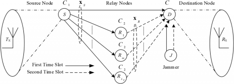
Cooperative communication is one of the most suitable and useful techniques for achieving spatial diversity in the nextgeneration wireless communication networks by enabling a SA user to function as a virtual MIMO system [32, 45]. A basic simplex model for the coded-cooperative wireless communication system consisting of multiple relays and a SA at the source node as well as at the destination node is depicted in Figure 1.
The source node $S$ is viewed as transmitting station $T_x$ with a single transmit-antenna, and the relay nodes $R_\omega$ comprise a single receive-antenna and a single transmit-antenna, where $\omega$ ranges from l-to- $L_R$ where $L_R$ denotes the total number of relays employed in the cooperative communication system. While the destination node D is considered as receiving station $R_x$ with a single receive-antenna. Two subsequent time slots are required to complete one transmission cycle from the source node $S$ to the destination node $D$. During the first time slot, the information sequence is broadcasted by the source node simultaneously to the relay nodes as well as to the destination node. Then, during the second time slot, the respective information sequence is transmitted to the destination node by each relay node. Since the relay nodes are located distant from one another, therefore their respective information sequences are transmitted over the channels which are non-overlapping. The binary input sequence of information bits $\boldsymbol{b}_0$ to the source node is encoded by the encoder $C_1$ into a codeword which is then modulated to generate the modulated output sequence of symbols, $\boldsymbol{x}_S=$ $\left[\boldsymbol{x}_S^1, \boldsymbol{x}_S^2, \boldsymbol{x}_S^3, \ldots, \boldsymbol{x}_S^{N_1^S}\right]$, where $x_S^j\left(j=1,2,3, \ldots, N_1^S\right)$ denotes the modulated symbols and $N_1^S$ being the sequence's length in bits. The source node broadcasts the modulated sequence of symbols $\boldsymbol{x}_S$ simultaneously to the relay as well as the destination nodes, during the first time slot. The coded symbols vector $\boldsymbol{y}_{S-D}$ received at the destination node in time slot 1 can be modelled as under:
Figure 1. General coded-cooperative communication model with multiple relays
$\boldsymbol{y}_{S-D}=\boldsymbol{h}_{S-D} \boldsymbol{x}_S+\boldsymbol{w}_{S-D}$ (1)
Under the jamming signal $\mathbf{z}^{J 1}$ during time slot 1,
$\boldsymbol{y}_{S-D}=\boldsymbol{h}_{S-D} \boldsymbol{x}_S+\boldsymbol{w}_{S-D}+\boldsymbol{g}_{J-D} \mathbf{z}^{J 1}$ (2)
where, the vector $\quad \boldsymbol{h}_{S-D}=$ $\left[h_{S-D}(1), h_{S-D}(2), h_{S-D}(3), \ldots, h_{S-D}\left(N_1^S\right)\right]$ represents the FSRF channel, $h_{S-D}(j) \sim R(0,1), \quad\left(j=1,2,3, \ldots, N_1^S\right)$ with uncorrelated zero-mean complex random variable having unit variance $\left(\sigma^2=1\right)$. Since slow-fading is considered in the FSRF channel, therefore, $\boldsymbol{h}_{S-D}$ converts into $\boldsymbol{h}_{S-D}=\left[h_{S-D}(1)=\right.$ $\left.h_{S-D}(2)=h_{S-D}(3)=, \ldots,=h_{S-D}\left(N_1^S\right)\right]$. The vector $\boldsymbol{w}_{S-D}=$ $\left[w_{S-D}(1), w_{S-D}(2), w_{S-D}(3), \ldots, w_{S-D}\left(N_1^S\right)\right]$ represents an AWGN vector, $w_{S-D}(j) \sim N\left(0, \sigma^2\right),\left(j=1,2,3, \ldots ., N_1^S\right)$ with zeromean and equal variance $\sigma^2=N_0 / 2$ per dimension, where $N_0$ being the noise power spectral density (PSD). The sequences of coded symbols vector, received at the destination node, are then combined together using the transmit diversity technique to obtain the $\boldsymbol{y}_{S-D}$ sequence. The term $\mathbf{z}^{J 1}$ is defined as the jamming signal during the first time slot [3], where $\mathbf{z}^{J 1}=\left[z_1, z_2, z_3, \ldots, z_{N_1^S}\right]^T \quad$ and $\quad \boldsymbol{g}_{J-D}=$ $\left[g_{J-D}(1), g_{J-D}(2), g_{J-D}(3), \ldots, g_{J-D}\left(N_1^S\right)\right]$ represents the FSRF channel from the jammer $J$ to the destination node $D$ in the first time slot, $g_{J-D}(j) \sim R\left(0, \sigma_J^2\right),\left(j=1,2,3, \ldots ., N_1^S\right)$ with zeromean and $\sigma_J^2=J_0 / 2$ variance complex Gaussian random variable, where $J_0$ is the jamming PSD.
The jamming signal can mathematically be represented as a wideband or broad-spectrum Gaussian noise for a fixed jammer received power $J$, with uncorrelated zero-mean and a flat PSD over the bandwidth under consideration. When the jammer's tactic is to jam the complete frequency-range $W_B$, this jammer is termed as a wideband noise or barrage jammer and $J_0=\left(J / W_B\right)$ is the jamming PSD [8]. However, in addition to white noise, the source of jamming, in this case, is considered as wideband Gaussian noise power from the jammer. Therefore, the SNR of interest can be written as $\gamma=\left[E_b /\left(N_0+J_0\right)\right]$, where $E_b$ represents the bit energy, J denotes the average jamming power received by the receiver and $W_B$ represents the entire frequency range of interest. Since the jamming PSD is usually far larger than the noise PSD, i.e., $J_0>N_0$, the typical $S N R$ in a jamming environment is generally considered to be $\gamma=E_b / J_0$. Thus, $\gamma_{\text {reqd. }}$ is defined as the bit energy per jamming PSD, needed to maintain the communication link for a definite BER [8], which can mathematically be expressed as under:
$\gamma_{\text {reqd. }}=\left(\frac{E_b}{J_0}\right)_{\text {reqd. }}=\frac{\left(W_B / \bar{R}\right)}{(J / S)_{\text {reqd. }}}=\frac{G_P}{(J / S)_{\text {reqd. }}}$ (3)
where, $E_b=S T_b=S / \bar{R}, S$ represents the received signal power, $T_b$ is the bit duration, $\bar{R}$ is the data rate (bits per second) and $G_P=\left(W_B / \bar{R}\right)$ represents the processing gain [8]. Therefore,
$\left(\frac{J}{S}\right)_{\text {reqd. }}=\frac{G_P}{\left(E_b / J_0\right)_{\text {reqd.}}}$ (4)
The parameter $(J / S)_{\text {reqd. }}$ is the required ratio of jamming power to signal power, which defines a figure-of-merit to measure the robustness and invulnerability of a system to interference. For further details on the subject of jamming and the parameters of the threat model assumed, interested readers may refer to the reference [8]. The coded symbol vector $\boldsymbol{y}_{S-R_\omega}$ received by the $\omega$-th relay node in time slot 1 can be modelled as under:
$\boldsymbol{y}_{S-R_\omega}=\boldsymbol{h}_{S-R_\omega} \boldsymbol{x}_S+\boldsymbol{w}_{S-R_\omega}$ (5)
Under the jamming signal $\mathbf{z}^{J 1}$ during time slot 1,
$\boldsymbol{y}_{S-R_\omega}=\boldsymbol{h}_{S-R_\omega} \boldsymbol{x}_S+\boldsymbol{w}_{S-R_\omega}+\boldsymbol{g}_{J-R_\omega} \boldsymbol{z}^{J 1}$ (6)
where, the vector $\boldsymbol{h}_{S-R_\omega}=$ $\left[h_{S-R_\omega}(1), h_{S-R_\omega}(2), \ldots, h_{S-R_\omega}\left(N_1^S\right)\right]$ represents the FSRF channel and $\boldsymbol{w}_{S-R_\omega}$ is an AWGN vector which can be specified likewise as $\boldsymbol{h}_{S-D}$ and $\boldsymbol{w}_{S-D}$ respectively. $\boldsymbol{g}_{J-R_\omega}=$ $\left[g_{J-R_\omega}(1), g_{J-R_\omega}(2), \ldots, g_{J-R_\omega}\left(N_1^S\right)\right]$ is the FSRF channel from the jammer $J$ to the $\omega$-th relay node $R_\omega$, defined similarly as $\boldsymbol{g}_{J-D}$. The detection process is accomplished at the relay node by decoding the received coded symbol vector $\boldsymbol{y}_{S-R_\omega}$ into information bits. The channel ( $\left.S-R_\omega\right)$ from the source to the $\omega$ th relay node is generally assumed to be ideal (i.e., SNR $\gamma_{S-R_\omega}=\infty$ ) to achieve perfect decoding at the relay node which is completely error-free. However, for a non-ideal $S-R_\omega$ channel (i.e., $S N R \gamma_{S-R_\omega} \neq \infty$ ), various cooperative protocols are described in the study of reference [27]. At the relay node, error-free decoding is ensured by using a cyclic redundancy check (CRC) which is given in the study of reference [27] for the cooperative protocol. However, in this research study, the $S$ - $R_\omega$ channel is considered ideal or perfect without jamming for the proposed model of coded-cooperative wireless communication. Several cooperative incremental redundancy hybrid automatic repeat request (ARQ) strategies for the slowfading half-duplex time-slotted multiple relay channel have been discussed in the study of reference [46].
The decoded bits are again encoded by the encoder $C_2$ at the relay node and then after modulation, during time slot 2 , these encoded bits are sent to the destination node. The modulated sequence of symbols is represented by $\boldsymbol{x}_R=$ $\left[\boldsymbol{x}_R^1, \boldsymbol{x}_R^2, \boldsymbol{x}_R^3, \ldots, \boldsymbol{x}_R^{N_2^R}\right]$, where $x_R^j\left(j=1,2,3, \ldots, N_2^R\right)$ denotes the modulated symbols and $N_2^R$ being the sequence's length in bits. The coded symbol vector $\boldsymbol{y}_{R_\omega-D}$ received at the destination node in time slot 2 can be modelled as under:
$\boldsymbol{y}_{R_\omega-D}=\boldsymbol{h}_{R_\omega-D} \boldsymbol{x}_R+\boldsymbol{w}_{R_\omega-D}$ (7)
Under the jamming signal $\mathbf{z}^{\text {J2 }}$ during time slot 2,
$\boldsymbol{y}_{R_\omega-D}=\boldsymbol{h}_{R_\omega-D} \boldsymbol{x}_R+\boldsymbol{w}_{R_\omega-D}+\boldsymbol{g}_{J-D} \mathbf{z}^{J 2}$ (8)
where, the vector $\boldsymbol{h}_{R_\omega-D}=$ $\left[h_{R_\omega-D}(1), h_{R_\omega-D}(2), h_{R_\omega-D}(3), \ldots, h_{R_\omega-D}\left(N_2^R\right)\right]$ represents the FSRF channel and $\boldsymbol{w}_{R_\omega-D}$ is an AWGN vector which can be specified likewise as $\boldsymbol{h}_{S-D}$ and $\boldsymbol{w}_{S-D}$ respectively. The term $\mathbf{z}^{J 2}$ is referred to as the jamming signal during the second time slot, defined similarly as $\mathbf{z}^{J 1}$ in Eq. (2), where $\mathbf{z}^{J 2}=$ $\left[z_1, z_2, z_3, \ldots, z_{N_2^R}\right]^T \quad$ and $\boldsymbol{g}_{J-D}=$ $\left[g_{J-D}(1), g_{J-D}(2), g_{J-D}(3), \ldots, g_{J-D}\left(N_2^R\right)\right]$ represents the FSRF channel from the jammer $J$ to the destination node $D$ during time slot $2, g_{J-D}(j) \sim R\left(0, \sigma_J^2\right),\left(j=1,2,3, \ldots \ldots, N_2^R\right)$ with zero-mean and $\sigma_J^2=J_0 / 2$ variance complex Gaussian random variable, where Jo represents the jamming PSD. The sequence of signals, transmitted by the relay nodes is received by the antenna at the destination node. The destination node then combines the received sequences by using the transmit diversity technique to get the $\boldsymbol{y}_{R_\omega-D}$ sequence. Both the channels, i.e., $S-D$ and $R_\omega-D$, are considered as FSRF channels which remain constant for one complete codeword and each node is supposed to have equal transmission power. The overall gain achieved in coded-cooperative communication is due to the path diversity and the codedcooperation of the relay node, which are both provided by adding one or more relay nodes [28]. Moreover, at the corresponding receivers, the perfect channel state information (CSI) is considered using BPSK/M-QAM modulation.
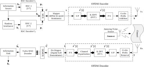
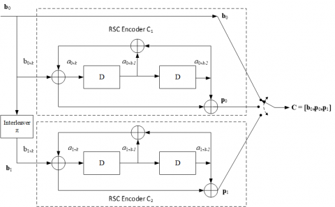
In this section, a brief overview of the proposed STC-OFDM scheme for a non-cooperative wireless communication system is presented and discussed, along with the details of the encoding and decoding processes (see Figure 2). A typical symmetric TCS consists of two identical RSC encoders concatenated in parallel, with a random interleaver (RI), denoted by $\pi$ as depicted in Figure 3, and a Turbo decoder, comprising of two constituent iterative soft-input/soft-output (SISO) decoders. The TCS with parallel concatenation is represented by $\boldsymbol{C}=\left(C_1, C_2\right)$, where $C_1$ and $C_2$ denote the same RSC encoders. In this manuscript, symmetric TCS having identical RSC encoders with constraint length $K_L=3$ and overall code rate $R_c=1 / 3$ is selected and investigated. Each encoder has the same generator matrix $\boldsymbol{G}(D)=\left[1, \boldsymbol{g}_2(D) / \boldsymbol{g}_1(D)\right]$, where $g_l(D)=\left(1+D+D^2\right)$ represents the feed-back polynomial and $\boldsymbol{g}_2(D)=\left(1+D^2\right)$ represents the feed-forward polynomial with constraint length $K_L=3$. The generator matrix $\boldsymbol{G}(D)$ of each encoder can also be represented in its equivalent octal form $\boldsymbol{G}(D)=(1,5 / 7)$ s. The TCS with overall generator matrix $\boldsymbol{G}(1,5 / 7,5 / 7)_8$ and code rate $R_c=1 / 3$ is considered and employed in the proposed AJ communication model because of its superior BER performance and robustness.
Figure 2. Block diagram of the proposed STC-OFDM scheme
Figure 3. A 1/3 code rate symmetric Turbo code encoder having generator matrix G(D)=(1,5/7,5/7)8 and constraint length KL=3
3.1 STC-OFDM encoder
The schematic diagram of the proposed STC-OFDM scheme is depicted in Figure 2. Let the sequence of message bits be represented by $b_0$ of frame length $l$, which is fed into the first RSC encoder $C_1$. This encoder produces a pair ( $\left.b_0, p_0\right)$ as an output, where $p_0$ represents the parity bits sequence, corresponding to the RSC encoder $C_1$. The message bits sequence $b_0$ is then given as input to a RI which produces the interleaved sequence of information bits $\boldsymbol{b}_1=\pi\left(\boldsymbol{b}_0\right)$. This interleaved sequence of information bits $b_1$ is passed through the second RSC encoder $C_2$ which produces another sequence of parity bits $p_1$, corresponding to the RSC encoder $C_2$. Thus, the final codeword produced after the operation of Turbo encoding is $C=\left[b_0, p_0, p_1\right]$ of length $N$. Then, a BPSK/M-QAM modulator (mapper) digitally modulates the Turbo encoded bit sequence $C$ and generates the sequence of coded symbols $s=\left[s_1, s_2, s_3, \ldots, s_k \ldots, s_N\right]$ of the same length $N$, where $k$ represents time instant of $s$ and $s_k$ represents binary BPSK or M-QAM digitally modulated symbols. This sequence of modulated symbols s is given as input to a serial-to-parallel (S/P) converter. These symbol vectors are represented as a vector of length $K$ for $i=1,2,3, \ldots, K$, such that $\boldsymbol{s}^f[i]=$ $\left\{s_1^f[i], s_2^f[i], s_3^f[i], \ldots, s_K^f[i]\right\}^T$, which are then multiplied by the $K$-point discrete Fourier transform (K-DFT) matrix $\boldsymbol{F}_K^{\bar{H}}$ given below [30], where $\bar{H}$ represents the Hermitian operator:
$F_K$$=\left[\begin{array}{cccc}1 & 1 & \cdots & 1 \\ 1 & \exp \left(-j \frac{2 \pi}{K}\right) & \cdots & \exp \left(-j \frac{2 \pi(K-1)}{K}\right) \\ \vdots & \vdots & \ddots & \vdots \\ 1 & \exp \left(-j \frac{2 \pi(K-1)}{K}\right) & \cdots & \exp \left(-j \frac{2 \pi(K-1)(K-1)}{K}\right)\end{array}\right]$ (9)
The K-point inverse fast Fourier transform (IFFT) operation is effectively performed by the above multiplication, which results in the parallel sequence of bits $s^t[i]$ for $i=1,2,3, \ldots, K$, as an output. Using a parallel-to-serial (P/S) converter, the serial sequence of bits is obtained which is then added to the cyclic prefix (CP) before transmission, resulting in the serial sequence signal vector $\boldsymbol{x}=$ $\left[s_{K-L_{C P}}^t, s_{K-L_{C P}+1}^t, s_{K-L_{C P}+2}^t, \ldots, s_{K-1}^t\right]^T$, where '$L_{C P}$' represents the size of the CP in bits. The impulse response $\boldsymbol{h}(n)$ of the signal $\boldsymbol{x}$, which propagates over a multipath FSRF channel [47, 48], is modelled as under:
$\boldsymbol{h}(n)=\sum_{p=0}^P h_p^n \bar{\delta}\left(n-\eta_p\right)$ (10)
where, $\bar{\delta}(\cdot)$ denotes the Dirac delta function and $\eta_p$ represents the delay associated with the $p$-th resolvable path, where $p=0,1,2, \ldots, P-1$, and $h_p^n$ represents the complex gain of the channel corresponding to the $p$-th resolvable path. The terms $h_p^n$ with various values of $p$ can be defined as the uncorrelated zero-mean, complex Gaussian random variables having variance $\sigma^2(p)$ and the total power of $P$ paths can be normalized so that $\sum_{p=0}^{P-1} \sigma^2(p)=1$ [48]. The phases of all the $P$ paths are independent and the phase of each path is uniformly distributed between 0 and $2 \pi$ radians [49]. For an AWGN channel, $\boldsymbol{h}(n)$ is generally considered to be unity, i.e., $\boldsymbol{h}(n)=1$. The detailed operation of the proposed STC-OFDM decoder is discussed in the subsequent subsection.
3.2 STC-OFDM decoder
The received signal vector $y(n)$ at the receiver can be modelled as under.
$\boldsymbol{y}(n)=\boldsymbol{h}(n) * \boldsymbol{x}(n)+\boldsymbol{w}(n)$ (11)
Under the jamming signal $\mathbf{z}^J(n)$,
$\boldsymbol{y}(n)=\boldsymbol{h}(n) * \boldsymbol{x}(n)+\boldsymbol{w}(n)+\boldsymbol{g}_J(n) \boldsymbol{z}^J(n)$ (12)
where, '∗' denotes the discrete-time (DT) linear convolution operator, the matrix $\boldsymbol{h}(n)$ represents the multipath FSRF channel with multiple taps, specified likewise in Eq. (10), $\boldsymbol{w}(n)$ is the corresponding noise vector, such that $\boldsymbol{w}(n)=$ $\left[w_{K-L_{C P}}^t, w_{K-L_{C P}+1}^t, w_{K-L_{C P}+2}^t, \ldots, w_{K+P}^t\right]^T$, with each element of $\boldsymbol{w}(n)$ being uncorrelated zero-mean complex Gaussian random variables having equal variance $\sigma^2=N_0 / 2$ per dimension and $N_0$ is the noise PSD. The term $z^J(n)=$ $\left[z_1, z_2, z_3, \ldots, z_N\right]^T$ is defined as the jamming signal of length $N$ emitted by the jammer $J$ with a single transmit-antenna and $\boldsymbol{g}_J(n)=\left[g_J(1), g_J(2), g_J(3), \ldots, g_J(N)\right]$ is the FSRF channel from the jammer $J$ to the receiver $R_x, g_J(j) \sim R\left(0, \sigma_J^2\right)$, $(j=1,2,3, \ldots, N)$ with zero-mean and $\sigma_J^2=J_0 / 2$ variance complex Gaussian random variable, where $J_0$ is the jamming PSD.
At the receiver, after removing $C P$, this signal is fed into the $S / P$ converter to produce the parallel signal vector $y^t[i]$. The $K$-point fast Fourier transform (FFT) operation is effectively performed by multiplying the $K$-DFT matrix $F_K$ defined in Eq. (9), with signal $\boldsymbol{y}^t[i]$. Consequently, the signal $y^f$ [i] is produced which is then given as input to the channel-equalizer to generate the received signal vector $r^f[i]$. Using the singletap channel frequency domain equalization (FDE) method at the receiver [30, 48], the received signal vector $r^f[i]$ is obtained which can be expressed as under:
$\boldsymbol{r}^f[i]=\boldsymbol{y}^f[i] / \boldsymbol{H}^f[i]$ (13)
where, $\boldsymbol{H}^f$ [i] represents the frequency response of multi-tap FSRF channel $\boldsymbol{h}(n)$, specified in Eq. (10), for $i=1,2,3, \ldots, K$. Using the $P /$ S converter, the received sequence of symbols $\hat{\boldsymbol{s}}=$ $r=\left[r_1, r_2, r_3, \ldots, r_k, \ldots, r_N\right]$ is obtained where $k$ represents the time instant of $s$. The received signal vector $\hat{\boldsymbol{s}}$ from the OFDM detector is given as input to the digital soft demodulator (demapper) to obtain log-likelihood ratios (LLRs) of each coded bit $\lambda=\left[\lambda_1, \lambda_2, \lambda_3, \ldots, \lambda_N\right]$, where the base of the natural logarithm is considered as $e$. These LLRs so obtained, are fed into Turbo decoder, resulting in the estimated sequence of information bits $\widehat{\boldsymbol{b}}_0$, which can mathematically be expressed as under:
$\operatorname{LLR}\left(s_k^{\bar{q}}\right)=\log \frac{P\left(s_K^{\bar{q}}=1 \mid r_k\right)}{P\left(s_K^{\bar{q}}=0 \mid r_k\right)}$ (14)
where, the bit position is defined by $\bar{q}$, such that $\bar{q}=1$ for the $B P S K$ demodulation. For the details of $M-Q A M$ soft demodulation, interested readers may refer to the existing literature [30]. These LLRs are then fed into the SISO decoder which finally outputs the estimated sequence of information bits $\widehat{\boldsymbol{b}}_0$, containing the original message bits $\boldsymbol{b}_0$. The decoding of Turbo codes is generally performed by employing the maximum likelihood detection (MLD) technique. In a characteristic Turbo decoder, the MLD decoding technique used is the log maximum a-posteriori probability (Log-MAP) algorithm which calculates the LLR of each bit based on the entire data block of frame length 1 under consideration. The decoding process of Turbo codes commences with forming $a$ posteriori probabilities (APPs) for each data bit, followed by selecting the data bit value corresponding to the maximum aposteriori probability (MAP) for that bit [8]. On receiving the code bit sequence that is corrupted, the decision-making process with APPs permits the Log-MAP algorithm to estimate the most likely information bit that is sent at each bit time. The Log-MAP decoding algorithm for Turbo codes is a recursive technique which performs on multiple iterations. The decoder1 after processing during the first iteration, results in estimating the systematic bits as LLRs. These LLRs along with the estimated message bits are called extrinsic information (IExt). This $I_{\text {Ext }}$ is fed into decoder-2, after interleaving. The decoder-2 receives the sequence of noisy parity bits and the $I_{\text {Ext }}$ from the decoder-1. The decoder-2 also produces its own $I_{\text {Ext }}$ which is sent as a-priori input to the decoder-1, after deinterleaving. The corresponding decoders exchange the $I_{\text {Ext }}$ of systematic bits for predetermined times of iterations, which finally produces the estimated sequence of message bits $\widehat{\boldsymbol{b}}_0$, after performing the slicing operation.
This section presents and discusses the proposed DSTCOFDM scheme for coded-cooperative wireless communication system, along with the details of the encoding and decoding processes (see Figure 4). In a typical symmetric TCS, the two identical RSC encoders can be distributed so that the first RSC is deployed at the source node and the second RSC is placed at the relay node. This distributed TCS having a parallel encoding structure is highly appropriate to be used in the coded-cooperative scenario, and thus a DSTC-OFDM scheme with RI is proposed and discussed in this section. The basic configuration of TCS is ideal for use in codedcooperative communication and such Turbo codes are usually termed as DTC in the literature [20] since they are created as a result of cooperation between the source node and the relay node. The generator polynomial employed for the distributed STC-OFDM scheme is $\boldsymbol{G}(1,5 / 7,5 / 7)_8$ with constraint length $K_L=3$. This DSTC-OFDM scheme requires two distinct time slots to transmit one complete Turbo code frame having the overall code rate $R_c=1 / 3$. The way TCS is structured makes it highly appropriate to deploy in a coded-cooperative communication system. It is disturbed over the source and relay nodes in such a way that cooperation occurs between these two nodes. The complete Turbo codeword is divided into two RSC codes. The RSC encoder-1 is located at the source node $S$ and the RSC encoder-2 is located at the relay node $R$. The $\omega$-th relay node $R_\omega$ is placed close to the destination node $D$ and the entire transmission cycle from the source node $S$ to the destination node $D$ is completed in two consecutive time slots. The source node is composed of a BPSK modulator and the RSC-1 encoder with $1 / 2$ code rate. The information sequence $b_0$ having frame length $l$ is encoded by the source node into coded sequence $q$ having length $N_1$. The original sequence of message bits $b_0$ from the source node is transmitted in two subsequent time slots.
Figure 4. Block diagram of the proposed DSTC-OFDM scheme
During time slot 1 , the source node encodes the sequence of message bits $\boldsymbol{b}_0$ into $q$ coded bits using the RSC-1 encoder. The sequence of RSC coded bits $q$ having length $N_1$ is digitally modulated by a BPSK modulator (mapper) to produce the coded symbol of sequence $s^1$. The acquired codeword $s^1$ is passed through an OFDM encoder, resulting in OFDM symbols $\boldsymbol{x}^S$, which are then broadcasted by the source node simultaneously to the destination node and all the relay nodes. The channel from the source to the $\omega$-th relay node ($\left.S-R_0\right)$ is generally assumed to be ideal without jamming (i.e., SNR $\gamma_{S-R_\omega}=\infty$), to achieve perfect decoding at the relay node which is completely error-free. The signal vector $\boldsymbol{y}_{S-R_\omega}$ received by the $\omega$-th relay can be modelled as under:
$\boldsymbol{y}_{S-R_\omega}(n)=\boldsymbol{h}_{S-R_\omega}(n) * \boldsymbol{x}^S(n)+\boldsymbol{w}_{S-R_\omega}(n)$ (15)
where, '∗' represents the DT linear convolution operator, the matrix $\boldsymbol{h}_{S-R_\omega}$ represents the multipath FSRF channel with multiple taps from the source to the $\omega$-th relay node, specified likewise in Eq. (10), $\boldsymbol{w}_{S-R_\omega}$ is the corresponding noise vector, such that $\boldsymbol{w}_{S-R_\omega}(n)=\left[w_1, w_2, w_3, \ldots, w_i, \ldots, w_{N_1}\right]$ where $w_i$ represents the uncorrelated zero-mean complex Gaussian random variable having equal variance $N_0 / 2$ per dimension and $N_0$ being the noise PSD. For a fast-fading channel, the $\boldsymbol{h}_{S-R_\omega}$ channel stays static during the transmission of one OFDM symbol. But, for the proposed scheme, the $\boldsymbol{h}_{S-R_\omega}$ channel remains constant for the transmission of one complete RSC codeword, i.e., $\boldsymbol{h}_{S-R_\omega}=\left[\boldsymbol{h}_{S-R_\omega}(1)=\boldsymbol{h}_{S-R_\omega}(2)=\right.$$\left.\boldsymbol{h}_{S-R_\omega}(3)=\ldots=\boldsymbol{h}_{S-R_\omega}\left(N_1\right)\right]$. Thus, the proposed model incorporates the slow fading in the FSRF channel. As the source node broadcasts only the first part of the codeword $x^s$ during time slot 1 , the signal vector $\boldsymbol{y}_{S-D}$ received at the antenna of the destination node in the same time slot can be modelled as under:
$\boldsymbol{y}_{S-D}(n)=\boldsymbol{h}_{S-D}(n) * \boldsymbol{x}^S(n)+\boldsymbol{w}_{S-D}(n)$ (16)
Under the jamming signal $\mathbf{z}^{J 1}(n)$ during time slot 1,
$\boldsymbol{y}_{S-D}(n)=\boldsymbol{h}_{S-D}(n) * \boldsymbol{x}^S(n)+\boldsymbol{w}_{S-D}(n)$$+\boldsymbol{g}_{J-D}(n) z^{J 1}(n)$ (17)
where, the matrix $\boldsymbol{h}_{S-D}=\left[\boldsymbol{h}_{S-D}(1)=\boldsymbol{h}_{S-D}(2)=\right.$ $\boldsymbol{h}_{S-D}(3)=\ldots .=\boldsymbol{h}_{S-D}\left(N_1\right)$] represents the multipath FSRF channel with multiple taps from the source to the destination, specified likewise in Eq. (10), $\boldsymbol{w}_{S-D}$ is the corresponding noise vector, such that $\boldsymbol{w}_{S-D}(n)=\left[w_1, w_2, w_3, \ldots, w_i, \ldots, w_{N_1}\right]$, defined similarly as $\boldsymbol{w}_{S-R_\omega}$. The term $\boldsymbol{z}^{J 1}$ is the jamming signal of length $N_1$ during the first time slot, defined similarly as $\mathbf{z}^J$ in Eq. (12), where $\mathbf{z}^{J 1}=\left[z_1, z_2, z_3, \ldots, z_{N_1}\right]^T$ and $g_{J-D}=$ $\left[g_{J-D}(1), g_{J-D}(2), g_{J-D}(3), \ldots, g_{J-D}\left(N_1\right)\right]$ represents the FSRF channel from the jammer $J$ to the destination node $D$.
The signal vector $\boldsymbol{y}_{S-D}$ received at the destination node is fed into an OFDM decoder which outputs the estimated coded symbols of sequence $\hat{s}^1$ during time slot 1 of the cooperative communication. However, the same signal also received at the $\omega$-th relay node, is given as input to an OFDM decoder which generates the estimated coded bits sequence $\hat{s}^l$ as an output. This estimated coded bits sequence $\hat{s}^1$ is passed through the BPSK demodulator and then the RSC SISO decoder, corresponding to the RSC-1 encoder, to obtain the estimated sequence of information bits $\widehat{\boldsymbol{b}}_0$ containing the original message bits $\boldsymbol{b}_0$. During time slot 2 , the estimated sequence of message bits $\widehat{\boldsymbol{b}}_0$ is fed into a RI which outputs the interleaved sequence of information bits $\boldsymbol{b}_1=\pi\left(\widehat{\boldsymbol{b}}_0\right)$. This interleaved sequence of information bits $\boldsymbol{b}_1$ is further given as input to a $1 / 2$ rate $R S C$ - 2 encoder, resulting in another sequence of parity bits $p_1$. The output of the RSC-2 encoder consists of an interleaved sequence of systematic bit $b_1$ and a parity bit sequence $p_1$. The sequence of systematic bits $b_1$ from the $R S C$ 2 encoder is discarded and only the sequence of parity bits $p_1$ is fed into the BPSK modulator.
The sequence of RSC coded bits $p_1$ having length $N_2$ is digitally modulated by a BPSK modulator (mapper) to generate the coded symbol of sequence $s^2$. The acquired codeword $s^2$ is passed through an OFDM encoder, resulting in the encoded OFDM symbols $\boldsymbol{x}^R$ which are then sent to the destination node. The received signal vector $\boldsymbol{y}_{R_\omega-D}$ at the destination node, during time slot 2 , can be modelled as under:
$\boldsymbol{y}_{R_\omega-D}(n)=\boldsymbol{h}_{R_\omega-D}(n) * \boldsymbol{x}^R(n)+\boldsymbol{w}_{R_\omega-D}(n)$ (18)
Under the jamming signal $\boldsymbol{z}^{J 2}(n)$ during time slot 2 ,
$\boldsymbol{y}_{R_\omega-D}(n)=\boldsymbol{h}_{R_\omega-D}(n) * \boldsymbol{x}^R(n)+\boldsymbol{w}_{R_\omega-D}(n)$$+g_{J-D}(n) z^{J 2}(n)$ (19)
where, the matrix $\boldsymbol{h}_{R_\omega-D}=\left[\boldsymbol{h}_{R_\omega-D}(1)=\boldsymbol{h}_{R_\omega-D}(2)=\right.$ $\left.\boldsymbol{h}_{R_{\omega-D}}(3)=\ldots=\boldsymbol{h}_{R_\omega-D}\left(N_2\right)\right]$ represents the multipath FSRF channel with multiple taps from the $\omega$-th relay node to the destination node, specified likewise in Eq. (10) and $\boldsymbol{w}_{R_\omega-D}$ is the corresponding noise vector, such that $\boldsymbol{w}_{R_\omega-D}(n)=\left[w_1, w_2, w_3, \ldots, w_i, \ldots, w_{N_2}\right]$, defined similarly as $\boldsymbol{w}_{S-R_\omega}$. The term $\boldsymbol{z}^{J 2}$ is the jamming signal of length $N_2$ during the second time slot, defined similarly as $\mathbf{z}^J$ in Eq. (12), where $z^{J 2}=\left[z_1, z_2, z_3, \ldots, z_{N_2}\right]^T$. At the destination node, the received signal $\boldsymbol{y}_{R_\omega-D}$ is given as input to the OFDM decoder which outputs the estimated coded symbols of sequence $\hat{s}^2$ during time slot 2 of the cooperative communication. Similarly, during the same time slot, the respective modulated sequences are sent by each relay to the destination node. The received symbol sequence from the antenna of the destination node is transformed into LLRs, which are then combined using the transmit diversity technique [19]. Finally, the received signals $\boldsymbol{y}_{S-D}$ and $\boldsymbol{y}_{R_\omega-D}$ are combined to form complete Turbo codes using the concatenation technique and then these codewords are rearranged to perform the corresponding joint iterative Turbo decoding operation. The destination node decodes the codewords by using the JISISO decoding technique for the DSTC-OFDM scheme which is explained in the subsequent section of this manuscript, to get the estimated sequence of information bits $\widehat{\boldsymbol{b}}_0$. The channels $S-D$ and $R_\omega-D$ are both considered to be FSRF channels which remain static for a complete RSC codeword and, therefore, incorporate slow fading. Moreover, all the nodes are supposed to have equal transmission power.
Another prominent and distinctive characteristic of the proposed DSTC-OFDM scheme for coded-cooperative wireless communication is the JSISO (Turbo) decoding technique. This decoder for the proposed DSTC-OFDM scheme, depicted in Figure 5, is implemented in the destination node, utilizing two SISO modules for joint iterative decoding operation. The SISO APP modules with both serial and parallel concatenation of Turbo codes for the iterative decoding are described by Benedetto et al. [50]. In a characteristic communications receiver, a demodulator generally generates soft decisions that are then fed into the soft-input/hard-output decoder, where the output of the decoder results in bits (i.e., hard decisions) after the final decoding process. However, a hard-output decoder is not suitable in a typical TCS, in which multiple component RSC encoders are employed. The Turbo decoding process of TCS consists of feeding the outputs in an iterative manner from one decoder back to the inputs of another decoder. This is because giving hard decisions as input to a decoder degrades the system performance as compared to soft decisions. Therefore, a SISO decoder is required for the decoding of Turbo codes [8]. For the first decoding iteration of such a SISO decoder; the binary data is usually assumed to be equally probable which gives an initial a-priori LLR value. In the iterative decoding process, the extrinsic likelihood is fed back to the decoder input, which leads to refining the a-priori probability of the data for the subsequent iteration.
Figure 5. Block diagram of the JISISO (Turbo) decoding technique for the proposed DSTC-OFDM scheme
5.1 Log-MAP decoding algorithm
In this subsection, the theoretical framework of the logMAP decoding algorithm with BPSK modulation is discussed. The natural logarithmic ratio of the APPs, i.e., the $LLRD\left(\hat{b}_{0, k}\right)$ of the $k$-th input data bit $b_{0, k}=i,(i=0,1)$, at time instant $k$ where $k=1,2, \ldots, l(l=512$ bits) and state $m$, can be given as under:
$D\left(\hat{b}_{0, k}\right)=\log \left[\frac{\sum_m \alpha_k^m \delta_k^{1, m} \beta_{k+1}^{f(1, m)}}{\sum_m \alpha_k^m \delta_k^{0, m} \beta_{k+1}^{f(0, m)}}\right]$ (20)
By comparing $D\left(\hat{b}_{0, k}\right)$ to a zero threshold, the SISO decoder uses the MAP decision rule to make a decision, i.e., $\widehat{b}_{0, k}=1$, if $D\left(\hat{b}_{0, k}\right)>0$ and $\hat{b}_{0, k}=0$, if $D\left(\hat{b}_{0, k}\right)<0$. $\alpha_k^m$ is defined as the forward state metric (FSM) at time $k$ and state $m$, as being a probability of the past sequence that only depends on the current state induced by this sequence. $\beta_k^m$ represents the reverse state metric (RSM) at time $k$ and state $m$, and $\beta_{k+1}^{f(i, m)}$ represents the RSM at future time $k+1$ and next state $f(i, m)$, as being a probability of the future sequence, depending upon the state at time $k+1 . \delta_k^{i, m}$ is defined as the branch metric ( $B M$ ) at time $k$ and state $m$. Interested readers may refer to the reference [8] for calculating the FSM $\alpha_k^m$, the $R S M \beta_k^m$ and the $B M \delta_k^{i, m}$.
Now, the $\operatorname{LLR} D\left(\hat{b}_{0, k}\right)$ of the $k$-th data bit of the original information sequence for the SISO decoder-1, can be expressed as under:
$D\left(\hat{b}_{0, k}\right)=\log \left[\rho_k \exp \left(\frac{2 \lambda_{b_{0, k}}}{\left(\sigma+\sigma_J\right)^2}\right)\left(\frac{\sum_m \alpha_k^m \exp \left(\frac{\lambda_{p_{0, k}} p_{0, k}^{1, m}}{\left(\sigma+\sigma_J\right)^2}\right) \beta_{k+1}^{f(1, m)}}{\sum_m \alpha_k^m \exp \left(\frac{\lambda_{p_{0, k}} p_{0, k}^{0, m}}{\left(\sigma+\sigma_J\right)^2}\right) \beta_{k+1}^{f(0, m)}}\right)\right]$ (21)
$D\left(\hat{b}_{0, k}\right)=\log \left[\rho_k \exp \left(\frac{2 \lambda_{b_{0, k}}}{\left(\sigma+\sigma_J\right)^2}\right) \rho_k^e\right]$ (22)
$D\left(\hat{b}_{0, k}\right)=\log \left(\rho_k\right)+\log \left[\exp \left(\frac{2 \lambda_{b_{0, k}}}{\left(\sigma+\sigma_J\right)^2}\right)\right]$$+\log \left(\rho_k^e\right)$ (23)
$D\left(\hat{b}_{0, k}\right)=D_{b_{21, k}}+D_c\left(\lambda_{b_{0, k}}\right)+D_{b_{12, k}}$ (24)
where, $b_{0, k}$ and $p_{0, k}$ denote the transmitted data bit and the corresponding parity bit, respectively at time $k$. The parameter $b_{0, k}^i$ is the data bit that is not dependent on the state $m$. However, the parameter $p_{0, k}^{i . m}$ is the parity bit that depends on the state $m$, due to the code's memory. The parameter $\rho_k=$$\rho_k^1 / \rho_k^0$ represents the input a-priori probability ratio, which is the prior likelihood for the SISO decoder-1, $\rho_k^i$ represents the a-priori probability of $b_{0, k}$ at time $k$, i.e., $P\left(b_{0, k}=i\right)$ and $\rho_k^e$ represents the output extrinsic likelihood at time $k$. $\rho_k^e$ can be considered as $I_{\text {Ext }}$ representing coding correction which changes the input prior knowledge of the data bit. The final soft number $D\left(\hat{b}_{0, k}\right)$ for the SISO decoder-1 consists of three $L L R$ terms, namely the a-priori $L L R D_{b_{21, k}}$, the channelmeasurement $L L R D_c\left(\lambda_{b_{0, k}}\right)$, and the extrinsic $L L R D_{b_{12, k}}$.
Similarly, the $\operatorname{LLR} D\left(\hat{b}_{1, k}\right)$ of the $k$-th data bit of interleaved information sequence for the SISO decoder-2, can be expressed as under:
$D\left(\hat{b}_{1, k}\right)=\bar{D}_{b_{12, k}}+D_c\left(\lambda_{b_{1, k}}\right)+\bar{D}_{b_{21, k}}$ (25)
where, $b_{1, k}$ represents the interleaved transmitted data bit in bipolar form at time $k$. $p_{1, k}$ represents the corresponding parity bit of $b_{1, k}$, defined similarly as $p_{0, k}$ in Eq. (21). Like the SISO decoder-1, the final soft number $D\left(\hat{b}_{1, k}\right)$ for the SISO decoder-2 consists of three LLR terms, namely the a-priori $\operatorname{LLR} \bar{D}_{b_{12, k}}$, the channel-measurement $\operatorname{LLR} D_c\left(\lambda_{b_{1, k}}\right)$, and the extrinsic $L L R \bar{D}_{b_{21, k}}$. In a typical TCS, the $I_{E x t}$ are exchanged from one decoder to another to improve the LLR for each data bit, and therefore reduce the decoding probability of error $\left(P_E\right)$. For several iterations, this decoding process can be used with the above equations to compute the LLR. For the next iteration, the a-priori likelihood ratio $\rho_{k+1}$ is replaced by the extrinsic likelihood $\rho_k^e$ resulting from a particular iteration.
5.2 JISISO (Turbo) decoding technique
The joint iterative Turbo decoder mainly consists of two SISO decoders, corresponding to each RSC code encoder. It has three separate inputs and a single output. The a-priori probabilities of systematic bits $\lambda_{\boldsymbol{b}_0}$ as well as parity bits $\lambda_{\boldsymbol{p}_0}$ and $\lambda_{\boldsymbol{p}_1}$, are fed into the SISO decoders, resulting in the extrinsic output $I_{\text {Ext. }}$ Each SISO decoder receives three distinct inputs, namely LLRs of systematic information bits, LLRs of parity bits and LLRs of a-priori information bits. It generates one output which is $I_{\text {Ext }}$ for the systematic bits and the parity bits. During time slot 1, the OFDM decoder generates the softbits LLRs $\lambda_D^1$, corresponding to the systematic bits $\boldsymbol{b}_0$ and the parity bits $p_0$ of the RSC-1 encoder, sent from the source node. The LLRs $\lambda_D^1$ are divided by the de-multiplexer into a couple of distinct streams of LLRs, i.e., $\lambda_{\boldsymbol{b}_0}$ (LLR corresponding to the systematic bits) and $\lambda_{p_0}$ (LLR corresponding to the parity bits $p_0$ of the RSC-1 encoder).
Both the systematic bits $L L R \lambda_{b_0}$ as well as the parity bits $L L R \lambda_{p_0}$ are passed through SISO Decoder-1 which produces the $I_{E x t} \boldsymbol{D}_{\boldsymbol{b}_{12}}$ as an output. This $I_{E x t}$ of systematic bits $\boldsymbol{D}_{\boldsymbol{b}_{12}}$ is fed into a RI which outputs the interleaved $I_{\text {Ext }}$ of systematic bits $\overline{\boldsymbol{D}}_{\boldsymbol{b}_{12}}$. This interleaved $I_{\text {Ext }}$ of systematic bits $\overline{\boldsymbol{D}}_{\boldsymbol{b}_{12}}$ is fed into SISO Decoder-2 as an a-priori input. During time slot 2 , the OFDM decoder produces the soft-bits $L L R s \lambda_D^2=\lambda_{p_1}(L L R$ corresponding to the parity bits $\boldsymbol{p}_1$ of the RSC-2 encoder), sent from the relay node to the destination node. The parity bit LLRs are passed through SISO Decoder-2 which generates the $I_{E x t} \overline{\boldsymbol{D}}_{\boldsymbol{b}_{21}}$ as an output, corresponding to the interleaved sequences of information bits $\boldsymbol{b}_1=\pi \boldsymbol{b}_0$. This $I_{E x t} \overline{\boldsymbol{D}}_{\boldsymbol{b}_{12}}$ is deinterleaved to form $I_{E x t} \boldsymbol{D}_{\boldsymbol{b}_{21}}$ which is fed back into the SISO Decoder-1. The respective SISO decoders exchange the $I_{E x t}$ of systematic bits for predetermined times of iterations. The interleaved $I_{E x t} \overline{\boldsymbol{D}}_{\boldsymbol{b}_{12}}$ and $\overline{\boldsymbol{D}}_{\boldsymbol{b}_{21}}$ are then summed up in an adder and de-interleaved after passing through a deinterleaver, which is followed by a slicer. Finally, the estimated sequence of information bits $\widehat{\boldsymbol{b}}_0$ is obtained, after performing the hard decoding operation by the slicer.
Cooperative communication schemes have effectively enabled SA users to allow their antennas to build a virtual MIMO system, which incorporates extra spatial diversity in wireless communication networks [20, 45]. However, the cooperative communication does have some drawbacks, such as the system's computational complexity and extra latency. In order to reduce the computational complexity and latency, the relay selection protocol is used to improve the overall performance of the cooperative communication system. The relay selection protocol allows the source node to work in cooperation with a single-relay node rather than multiple relay nodes in the cooperative communication systems [51]. In this manuscript, the relay-assisted DF cooperative protocol is employed in which a source node transmits to a destination node through a direct link as well as through an indirect link via multiple relay nodes. In a classical multi-relay cooperative communication system, all the relay nodes transmit the signal received from the source node to the destination node, using orthogonal sub-channels called subcarriers to avoid cochannel interference [52]. Therefore, for the $L_R$-relays classical cooperative communication network, there are a total of $\left(L_R+1\right)$ channels required, i.e., one channel for the direct path and $L_R$ channels for the $L_R$ indirect paths. With an additional number of relays, the number of required channels also increases linearly which suffers a bandwidth trade-off. However, the best relay selection (BRS) technique resolves the issue of the inefficient utilization of the available channel bandwidth. In a typical BRS scheme, only the best relay node is considered to transmit the signal to the destination node, and therefore, irrespective of the total number of relays $L_R$, this technique requires only two channels, one for the direct path and the other one for the best indirect path [52].
In this section, the BRS technique has been proposed, based on the highest SNR, where only the best relay participates in the relaying process under noise jamming environment. The best relay can be considered as that relay node which attains the highest SNR at the destination node [52]. The BRS scheme not only minimizes the number of channel resources needed but also maintains the same BER performance, which can be achieved otherwise by the classical multi-relay cooperative communication network with a significantly increased number of resources. Thus, the efficient resource usage by the BRS technique does not result in degrading the quality of the signal. The communication link is established between the source node $S$ and the destination node $D$ through a direct link $(S \rightarrow D)$ and an indirect link $(S \rightarrow R \omega \rightarrow D)$ via the best relay node $R_\omega$, as shown in Figure 1. In this scheme, the destination node receives the complete codeword from the source node and the $\omega$-th relay node. The systematic bits $\boldsymbol{b}_0$ and parity bits $\boldsymbol{p}_0$ are received from the source (direct link), while the parity bit $\boldsymbol{p}_1$ is received from the best relay with the highest SNR (indirect link). The channel coefficients between the source $S$ and the $\omega$-th relay $R_\omega\left(\boldsymbol{h}_{S-R_\omega}\right)$, between the $\omega$-th relay node $R_\omega$ and the destination $D\left(\boldsymbol{h}_{R_\omega-D}\right)$ and between the source $S$ and the destination $D\left(\boldsymbol{h}_{S-D}\right)$ are FSRF coefficients. In addition, these coefficients $\boldsymbol{h}_{S-R_\omega}, \boldsymbol{h}_{R_\omega-D}$, and $\boldsymbol{h}_{S-D}$ are mutually independent and non-identical for all values of $\omega$. Moreover, the Gaussian noise terms of all the links are assumed to have zero-mean and equal variance $N_0 / 2$ per dimension. In order to maintain the relay power within its specified limits, particularly if the fading coefficient $\boldsymbol{h}_{S-R_\omega}$ is low [52], the relaying gain is kept equal to $\sqrt{1 /\left(E_S h_{S-R_\omega}+N_0+J_0\right)}$, where $E_S$ denotes the signal energy transmitted by the source, $N_0$ and $J_0$ represent the noise $P S D$ and jamming $P S D$ respectively. Therefore the total SNR of the indirect link $\left(S \rightarrow R_\omega \rightarrow D\right.$ ) is expressed as under:
$\gamma_{S \rightarrow R_\omega \rightarrow D}=\frac{\gamma_{S-R_\omega} \gamma_{R_\omega-D}}{\gamma_{S-R_\omega}+\gamma_{R_\omega-D}+1}$ (26)
where, $\gamma_{S-R_\omega}=\boldsymbol{h}_{S-R_\omega}^2 \frac{E_S}{\left(N_0+J_0\right)}$ is the instantaneous value of SNR of the source signal at $R_\omega$ and $\gamma_{R_{\omega^{-D}}}=\boldsymbol{h}_{R_\omega-D}^2 \frac{E_\omega}{\left(N_0+J_0\right)}$ is the instantaneous value of SNR of the relayed signal by $R_\omega$ at $D$, where $E_\omega$ denotes the signal energy transmitted by the best relay node. Furthermore, $\gamma_{S-D}=\boldsymbol{h}_{S-D}^2 \frac{E_S}{\left(N_0+J_0\right)}$ is the instantaneous value of SNR of the signal between $S$ and $D$. The relay node attaining the highest SNR of the indirect link $\left(S \rightarrow R_\omega \rightarrow D\right)$ is selected as the best relay. The maximum $S N R$ $\left(\gamma_{B R S}\right)$ of the best relay node for the BRS technique can now be expressed as under:
$\gamma_{B R S}=\gamma_{\left(S \rightarrow R_\omega \rightarrow D\right)_{\max }}=\max _\omega\left(\frac{\gamma_{S-R_\omega} \gamma_{R_\omega-D}}{\gamma_{S-R_\omega}+\gamma_{R_\omega-D}+1}\right)$ (27)
This section presents the BER performances and simulation results of the proposed STC-OFDM (non-cooperative) scheme and the DSTC-OFDM (coded-cooperative) scheme over the AWGN channel as well as the FSRF channel. The simulation tool, modulation technique and decoding algorithm employed for the conventional STC-OFDM scheme and distributed STC-OFDM scheme are MATLAB, BPSK/M-QAM modulation, and Log-MAP algorithm respectively. Both of the proposed schemes have been investigated and analyzed under the same wideband noise jamming environment and identical conditions i.e., the same overall code rate and frame length of Rc=1/3 and l=512 bits respectively. The generator matrix for both the schemes is G(1,5/7, 5/7)8 having the length of RI equal to the frame length l=512 bits. The STC-OFDM and DSTC-OFDM schemes are simulated over AWGN and multipath FSRF channels. However, the DSTC-OFDM scheme is also analyzed with both single-relay as well as multiple relays at the relay node. The multiple relays are assumed to be in cooperation at all times. In addition, the proposed DSTC-OFDM scheme can achieve both cooperative diversity gain as well as coding gain. In this research study, the channels S-D and Rω-D are considered to be multipath FSRF channels which are statistically independent and modelled by the Monte Carlo method with 9 taps each [47, 49]. However, for all simulations in the coded-cooperative scenario, the S-Rω channel is supposed to be an ideal channel (i.e., SNR $\gamma_{\mathrm{S}-R_\omega}=\infty$). This hypothesis is valid due to the fact that the DF cooperative protocol [23, 24] is applicable only when the S-D channel is severely degraded as compared to the S-Rω channel. For the multipath FSRF channels between different links, the delay spread is considered to be 9 bits and the phase of each path is uniformly distributed between 0 and 2π radians [48]. The length of IFFT and CP is selected to be 64 and 16 bits respectively, based on the IEEE 802.11a specifications for a wireless communication link built using OFDM [53]. The 802.11a standard for wireless local area (WLAN) networking operates in the 5 GHz frequency band and specifies multiple non-overlapping channels, each with a width of 20 MHz, within the 5 GHz range which are spread apart to reduce interference [53]. Moreover, in the context of 802.11a which uses OFDM, the effects of the Rayleigh fading channel are particularly relevant, capturing the random and time-varying characteristics of multipath fading.
In this paper, we have modelled the effect of wideband noise jamming by utilizing the noise parameter jamming-to-signal (J/S) ratio [8]. This parameter J/S is primarily used to model the impact of a noise source that may affect the received signal, while processing the legitimate signal. It is used in SNR calculation (i.e., $\gamma_{\text {reqd. }}$) as shown in Eq. (3) for determining the quality of a signal. We have used a jamming source with a SA to generate a random pseudo-noise (PN) sequence to jam the receiver Rx or the destination node D as defined in Eq. (6) and Eq. (8). The J/S ratio is taken to be 13dB, 23 dB and 33dB for the processing gain of GP=1000 [8]. Here, we have used three different values of the J/S ratio depending on the distance of the jammer from the receiver Rx or the destination node D, while taking into account the effect of the jammer’s current position. We have catered the impact of the jammer’s distance with the help of the parameter J/S such that the value of the J/S ratio increases with the decrease in distance from the jammer to the receiver Rx or the destination node D. Furthermore, the AJ strategies offered by the simulation results, so obtained from this research study, are not optimal for covering all possible aspects of jamming attacks. Certain aspects of jamming signals, including the temporal and frequency patterns, can be optimized, and then those sensitive components of the wireless communication system that are more vulnerable to jamming attacks are optimally selected [3]. In this research, however, the prime focus is given only on the relatively under-investigated class of the jamming attack, namely wideband Gaussian noise jamming, and provides specific insight on how to counter the potential effect of the wideband noise jamming attack.
For relaying, each relay node is placed close to the destination node, to obtain an edge in SNR over the source node. If only one relay node is employed, it is assumed to have an additional gain in SNR, i.e., +3dB over the source node. If three relay nodes are employed, all the relays are assumed to have equal gain in SNR, i.e., +3dB over the source node. Moreover, at the destination node, the JISISO decoding technique is used and in each simulation, the SNR per bit is employed. Moreover, in this research study, perfect CSI is assumed using BPSK/M-QAM modulation, at the corresponding receivers. Several basic channel estimation (CE) techniques to estimate the RF channel in wireless OFDM systems, namely pilot-mode CE, training-mode CE, transform domain CE, LMMSE CE, decision-directed CE and CE with pilot contamination have been covered in the literature [15, 54].
The complete list of parameters with specifications used in the simulation is summarized in Table 1, given as under:
Table 1. List of simulation parameters
|
Parameters |
Specification |
|
Modulation techniques |
BPSK |
|
M-QAM |
|
|
Multiplexing scheme |
OFDM |
|
FFT length (K) |
64 bits |
|
Number of data subcarriers |
52 |
|
CP length LCP |
16 bits |
|
OFDM symbol size |
64+16=80 bits |
|
FFT sampling frequency |
20 MHz [-10MHz to +10MHz] |
|
Subcarrier spacing |
312.5 KHz |
|
Used subcarrier index |
{-26 to -1, +1 to +26} |
|
CP duration (TCP) |
0.8 µs |
|
OFDM symbol duration (Td) |
3.2 µs |
|
OFDM symbol duration (Ts) |
4 µs |
|
OFDM equalization technique |
FDE |
|
Channel models |
AWGN channel, Rayleigh fading channel |
|
Fading model |
FSRF |
|
Delay spread of a channel |
9 bits |
|
Multipath taps |
9 taps |
|
Multipath phase-shift |
0 - 2π radians |
|
Additional relay gain |
+3 dB |
|
Channel coding |
TCS |
|
Generator polynomial for TCS |
(1,5/7,5/7)8 |
|
Data frame length (l) |
512 bits |
|
Turbo code frame size |
512×3=1536 bits |
|
Number of frames |
100,000 |
|
Code rate (Rc) |
1/3 |
|
Decoding technique |
JISISO - Turbo |
|
Decoding algorithm |
Log-MAP |
|
Log-MAP iterations |
5 |
|
Jamming-to-Signal (J/S) ratio |
13, 23 and 33 dB |
|
Processing gain (GP) |
1000 |
7.1 Performance comparison between STC-OFDM (non-cooperative) scheme and single-relay DSTC-OFDM (coded-cooperative) scheme with and without jamming over AWGN channel
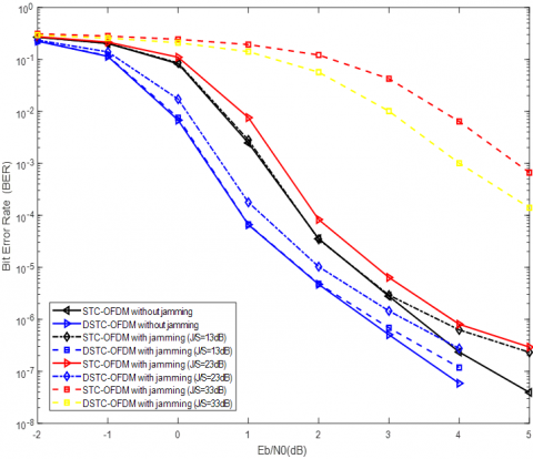
In this subsection, we present the BER performance comparison of conventional STC-OFDM scheme for non-cooperative communication and single-relay distributed STC-OFDM scheme for coded-cooperative communication over AWGN channel under non-jamming and different jamming environments, as shown in Figure 6(a). The simulation results reveal that the DSTC-OFDM outperforms the non-cooperative STC-OFDM over the AWGN channel with the BPSK modulation technique under both non-jamming and different jamming environments for the entire SNR range under consideration as shown in Figure 6(a). The BER curves also show that the performance gain of DSTC-OFDM at BER ≈ 4×10⁻⁷ over STC-OFDM is 0.8 dB without jamming. Furthermore, the BER curves with jamming J/S=13dB, 23dB and 33dB show that the performance gain of DSTC-OFDM at BER ≈ 7×10⁻⁷, 1.5×10⁻⁶ and 1×10⁻³ over STC-OFDM is 1dB, 0.8dB and 0.9dB respectively. The underlying reason behind the better performance of DSTC-OFDM over STC-OFDM is due to the path diversity provided by the relay node.
In Figure 6(b), the BER performance comparison of the STC-OFDM scheme for non-cooperative communication and single-relay DSTC-OFDM scheme for coded-cooperative communication is presented over AWGN channel under non-jamming and jamming environments with different modulation techniques, namely BPSK, 4-QAM and 16-QAM. The Monte Carlo results reveal that the BPSK modulation technique performs better in terms of the BER for both the STC-OFDM and DSTC-OFDM schemes. However, in terms of bandwidth efficiency, the 16-QAM modulation technique is better as compared to BPSK and 4-QAM modulation techniques.
Figure 6(a). BER performance of STC-OFDM (Non-cooperative) scheme and single-relay DSTC-OFDM (Coded-cooperative) scheme over AWGN channel, with BPSK modulation technique, frame length l=512 bits, 100,000 No. of frames and 5 decoding iterations
Figure 6(b). BER performance of STC-OFDM (Non-cooperative) scheme and single-relay DSTC-OFDM (Coded-cooperative) scheme over AWGN channel, with different modulation techniques (BPSK, 4-QAM and 16-QAM), frame length l=512 bits, 100,000 No. of frames and 5 decoding
7.2 Performance comparison between STC-OFDM (non-cooperative) scheme and single-relay DSTC-OFDM (coded-cooperative) scheme with and without jamming over single-path FSRF channel
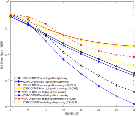
This subsection presents the BER performance comparison of conventional STC-OFDM scheme for non-cooperative communication and single-relay distributed STC-OFDM scheme for coded-cooperative communication over Single-path FSRF channel (both slow-fading and fast-fading) under non-jamming and jamming environments, as shown in Figure 7.
Figure 7. BER performance of STC-OFDM (Non-cooperative) scheme and single-relay DSTC-OFDM (Coded-cooperative) scheme over single-path FSRF channel (both slow-fading and fast-fading), with BPSK modulation technique, frame length l=512 bits, 100,000 No. of frames and 5 decoding iterations
The simulation results show that in the low SNR region, the non-cooperative STC-OFDM performs almost similar to the DSTC-OFDM, however, in the high SNR region the DSTC-OFDM performs far better than the STC-OFDM by a gain of 2 dB at BER ≈ 1×10⁻² over single-path slow FSRF channel without jamming. Similarly, DSTC-OFDM outperforms the non-cooperative STC-OFDM by a gain of 1 dB at BER ≈ 2.5×10⁻² over the aforementioned channel with jamming J/S=23dB. Moreover, the simulation results show that the DSTC-OFDM outperforms the STC-OFDM by a gain of 6 dB at BER ≈ 6×10⁻⁴ over a single-path fast FSRF channel without jamming. Similarly, the DSTC-OFDM outperforms the STC-OFDM by a gain of 6 dB at BER ≈ 9×10⁻³ over the aforementioned channel with jamming J/S=23dB. Furthermore, the simulation results reveal that the STC-OFDM and the DSTC-OFDM schemes perform better in terms of the BER over the fast FSRF channel in comparison to the slow FSRF channel under both jamming and non-jamming scenarios.
7.3 Performance comparison between STC-OFDM (non-cooperative) scheme and single-relay DSTC-OFDM (coded-cooperative) scheme with and without jamming over multipath FSRF channel
In this subsection, we present the BER performance comparison of conventional STC-OFDM scheme for non-cooperative communication and single-relay distributed STC-OFDM scheme for coded-cooperative communication over multipath FSRF (slow) channel with 9-taps under non-jamming and jamming environment, as shown in Figure 8. The simulation results show that in the low SNR region, the non-cooperative STC-OFDM performs almost similar to the DSTC-OFDM, however, in the high SNR region the DSTC-OFDM performs far better than the STC-OFDM by a gain of 2.5 dB at BER ≈ 2.5×10⁻³ over multipath FSRF channel without jamming. Similarly, the DSTC-OFDM outperforms the STC-OFDM by a gain of 2.5 dB at BER ≈ 1×10⁻² over multipath FSRF channel with jamming J/S=23dB.
Figure 8. BER performance of STC-OFDM (Non-cooperative) scheme and single-relay DSTC-OFDM (Coded-cooperative) scheme over multipath FSRF (slow) channel with 9-taps, with BPSK modulation technique, frame length l=512 bits, 100,000 No. of frames and 5 decoding iterations
Moreover, the improved BER performance of both the proposed schemes over multipath FSRF channel as compared to single-path FSRF channel is due to the use of the OFDM technique which helps mitigate the impact of the FSRF, providing reliable wireless communication.
7.4 Performance comparison between single-relay DSTC-OFDM (coded-cooperative) scheme with different jamming scenarios over multipath FSRF channel
This subsection presents the BER performance comparison of single-relay distributed STC-OFDM scheme for coded-cooperative communication over multipath FSRF (slow) channel with 9-taps, under different jamming scenarios, as shown in Figure 9, which are as follows:
-Both R-D and S-D Paths are considered without jamming;
-The R-D path is with jamming while the S-D path is without jamming;
-The S-D path is with jamming while the R-D path is without jamming;
-Both R-D and S-D Paths are considered with jamming.
The simulation results show that the DSTC-OFDM with R-D path jamming outperforms DSTC-OFDM with S-D path jamming by a gain of 7 dB at BER ≈ 9×10⁻³ over multipath FSRF (slow) channel with jamming J/S=23dB. However, with jamming J/S=13dB, the simulation results show that the DSTC-OFDM with R-D path jamming outperforms DSTC-OFDM with S-D path jamming by a gain of 3 dB at BER ≈ 1×10⁻³ over multipath FSRF channel.
Figure 9. BER performance of single-relay DSTC-OFDM (Coded-cooperative) scheme over multipath FSRF (slow) channel, under different jamming scenarios with BPSK modulation technique, frame length l=512 bits, 100,000 No. of frames and 5 decoding iterations
Similarly, the gain of 2 dB is observed at BER ≈ 1×10⁻² for the DSTC-OFDM with S-D path jamming only over the DSTC-OFDM with both S-D and R-D paths jamming (J/S=23dB) over multipath FSRF channel. However, the gain of 9 dB is observed at BER ≈ 9×10⁻³ for the DSTC-OFDM with R-D path jamming only over the DSTC-OFDM with both S-D and R-D paths jamming (J/S=23dB) over the aforementioned channel model. The gain of 0.5 dB is observed at BER ≈ 1.2×10⁻³ for the DSTC-OFDM with S-D path jamming only over the DSTC-OFDM with both S-D and R-D paths jamming, over multipath FSRF channel with jamming J/S=13dB. However, the gain of 5 dB is observed at BER ≈ 9×10⁻⁴ for the DSTC-OFDM with R-D path jamming only over the DSTC-OFDM with both S-D and R-D paths jamming over the aforementioned channel with jamming J/S=13dB. Furthermore, the performance of DSTC-OFDM with both S-D and R-D path jamming (J/S=23dB) is the worst amongst all the compared schemes over a multipath FSRF channel under different jamming scenarios.
7.5 Performance comparison between single-relay and multi-relay DSTC-OFDM (coded-cooperative) scheme with and without jamming over multipath FSRF channel
The last subsection presents the BER performance comparison of single-relay and multi-relay distributed STC-OFDM scheme for coded-cooperative communication over multipath FSRF (slow) channel with 9-taps, under non-jamming and jamming environment, as shown in Figure 10. According to the Monte Carlo simulation results, the multi-relay DSTC-OFDM scheme outperforms its corresponding single-relay DSTC-OFDM scheme under identical conditions for the entire SNR range under consideration as shown in Figure 10. In the case of three relay nodes, the multi-relay DSTC-OFDM scheme for coded-cooperative communication gives 7 dB gain over the single-relay DSTC-OFDM scheme at BER » 1´10-3 over multipath FSRF channel without jamming. Similarly, for three relay nodes, the multi-relay DSTC-OFDM scheme for coded-cooperative communication gives a 5 dB gain over the single-relay DSTC-OFDM scheme at BER » 1´10-2 over the aforementioned channel with jamming J/S=23dB.
Figure 10. BER performance of single-relay and multi-relay DSTC-OFDM (Coded-cooperative) scheme over multipath FSRF (slow) channel, with BPSK modulation technique, frame length l=512 bits, 100,000 No. of frames and 5 decoding iterations
Moreover, for the BRS technique, based on the highest SNR, the gain of 4 dB is observed at BER ≈ 1.5×10⁻³ over the single-relay DSTC-OFDM scheme with the same modulation technique, over multipath FSRF channel without jamming. However, the gain of 5 dB is observed at BER » 1×10⁻² for the BRS technique, over the single-relay DSTC-OFDM scheme over the aforementioned channel with jamming J/S=23dB.The bit error performance of the three-relay DSTC-OFDM scheme is superior to that of the single-relay DSTC-OFDM scheme under the same circumstances. The improved bit error performance for multiple relays is due to the increased SNR as additional relays are located near the destination node. Furthermore, the deployment of multiple relays in the vicinity of the destination node enhances the information reliability of the communication link by offering spatial diversity gain.
In this research paper, an effective and innovative AJ technique is proposed by investigating the BER performance of the DSTC-OFDM scheme for coded-cooperative wireless communication under wideband noise jamming environment. As an appropriate benchmark to our proposed scheme, the conventional STC-OFDM scheme is also simulated and analyzed for non-cooperative wireless communication, under the same jamming environment. The prime modulation technique and the decoding algorithm employed for the STC-OFDM (non-cooperative) scheme and DSTC-OFDM (coded-cooperative) scheme are BPSK modulation and Log-MAP algorithm respectively. Soft demodulators are employed along with the JISISO (Turbo) decoding technique at the destination node for coded-cooperation. The BER performance of both the proposed schemes have been analyzed and compared over the stated channel models under the same conditions, i.e., the code rates and data frame lengths of Rc=1/3 and l=512 data bits respectively for both the schemes. The Monte Carlo simulation results reveal that the DSTC-OFDM scheme outperforms the STC-OFDM scheme by a gain that ranges between 1–7 dB for different values of J/S ratio in the high SNR simulated region, under the same circumstances and noise jamming environment. However, in the low SNR simulated region, the STC-OFDM scheme shows similar performance as the DSTC-OFDM scheme, under identical conditions. Moreover, the proposed DSTC-OFDM scheme is further studied in coded-cooperative communication with multiple relays and BRS technique under the jamming environment over a multipath FSRF channel. In addition, this scheme incorporates both cooperative diversity gain and coding gain. Furthermore, adding more relay nodes in the vicinity of the destination node enhances the information reliability of a communication link by offering spatial diversity, thereby further improving the BER performance by a gain of 5-7 dB.
The proposed DSTC-OFDM scheme, a hybrid combination of Turbo coding with OFDM in cooperative wireless communication, overcomes most of the limitations of existing AJ techniques. Although several queries associated with the BER performance of STC-OFDM system under wideband noise jamming are still unresolved, we are so far convinced to believe that TCS in combination with OFDM is the competitive AJ channel coding technique and certainly the next-generation of secure wireless communication technology. In future work, the BER performance of the proposed AJ schemes can further be analyzed for improvement, over different MIMO techniques, by deploying multiple transmit and receive antennas.
|
b0 |
Information or message bit sequence |
|
b0,k |
k-th input data bit |
|
b1 |
Interleaved information bit sequence |
|
b1,k |
k-th interleaved data bit |
|
C |
Turbo codeword |
|
C1 |
RSC encoder-1 |
|
C2 |
RSC encoder-2 |
|
dfree |
Code’s effective free distance |
|
D |
Destination node |
|
Db |
Extrinsic information |
|
$\overline{\mathbf{D}}_{\mathrm{b}}$ |
Interleaved extrinsic information |
|
Dc |
Channel-measurement LLR |
|
$\mathrm{D}\left(\hat{\mathrm{b}}_{0, \mathrm{k}}\right)$ |
LLR of k-th input data bit |
|
$\mathrm{D}\left(\hat{\mathrm{b}}_{1, \mathrm{k}}\right)$ |
LLR of interleaved k-th input data bit |
|
Eb |
Bit energy (Joules) |
|
f(i,m) |
Next state at future time k+1 |
|
G |
Generator matrix |
|
gJ |
FSRF channel from jammer to receiver |
|
gJ-D |
FSRF channel from jammer to destination |
|
GP |
Processing gain |
|
h |
FSRF channel vector |
|
J |
Jammer |
|
J0 |
Jamming power spectral density |
|
J/S |
Jamming-to-Signal ratio |
|
K |
FFT length |
|
KL |
Constraint length |
|
k |
Time instant of the input sequence |
|
L |
Data frame length |
|
LCP |
Length of cyclic prefix |
|
LR |
Total number of relays employed |
|
m |
State at time instant k |
|
N0 |
Noise power spectral density |
|
$\mathrm{N}_1^{\mathrm{S}}, \mathrm{N}_1$ |
Received sequence’s length in bits from source S |
|
$\mathrm{N}_2^{\mathrm{R}}, \mathrm{N}_2$ |
Received sequence’s length in bits from relay R |
|
p |
Resolvable path in multipath FSRF channel |
|
P |
Total number of resolvable paths |
|
p0 |
Parity bits corresponding to the C1 encoder |
|
p0,k |
k-th parity bit corresponding to the C1 encoder |
|
p1 |
Parity bits corresponding to the C2 encoder |
|
p1,k |
k-th parity bit corresponding to the C2 encoder |
|
$\overline{\mathrm{R}}$ |
Data rate (bps) |
|
Rc |
Turbo code rate |
|
Rω |
ω-th Relay node |
|
Rx |
Receive station |
|
S |
Source node |
|
Tb |
Bit duration (s) |
|
Tx |
Transmit station |
|
w |
AWGN vector |
|
WB |
Entire bandwidth of interest (Hz) |
|
xS |
Modulated sequence of symbols transmitted by the source |
|
xS |
OFDM encoded Turbo codeword sequence transmitted by the source |
|
xR |
Modulated sequence of symbols transmitted by the relay |
|
xR |
OFDM encoded Turbo codeword sequence transmitted by the relay |
|
y |
Received coded symbols vector |
|
zJ |
Wideband noise jamming signal |
|
zJ1 |
Jamming signal during the first time slot |
|
zJ2 |
Jamming signal during the second time slot |
|
Greek symbols |
|
|
$\alpha_{\mathrm{k}}^{\mathrm{m}}$ |
Forward state metric at time k and state m |
|
$\beta_{\mathrm{k}}^{\mathrm{m}}$ |
Reverse state metric at time k and state m |
|
$\beta_{\mathrm{k}+1}^{\mathrm{f}(\mathrm{i}, \mathrm{m})}$ |
Reverse state metric at future time k+1 and next state f(i,m) |
|
$\gamma$ |
SNR (signal-to-noise ratio) |
|
$\delta$ |
Time slot of cooperative communication |
|
$\delta_{\mathrm{k}}^{\mathrm{i}, \mathrm{m}}$ |
Branch metric at time k and state m |
|
$\bar{\delta}(\cdot)$ |
Dirac delta function |
|
$\eta_{\mathrm{p}}$ |
Delay associated with the p-th path |
|
$\lambda$ |
Soft-bits LLR |
|
$\rho_{\mathrm{k}}$ |
Input a-priori probability ratio at time k |
|
$\rho_{\mathrm{k}}^{\mathrm{e}}$ |
Output extrinsic likelihood at time k |
|
σ |
Standard deviation of the AWGN |
|
σJ |
Standard deviation of the jamming signal |
|
σ2 |
AWGN Variance |
|
$\sigma_{\mathrm{J}}^2$ |
Jamming signal variance |
|
ω |
Relay number |
[1] Pirayesh, H., Zeng, H. (2022). Jamming attacks and anti-jamming strategies in wireless networks: A comprehensive survey. IEEE Communications Surveys & Tutorials, 24(2): 767-809. https://doi.org/10.1109/COMST.2022.3159185
[2] Zou, Y., Zhu, J., Wang, X., Hanzo, L. (2016). A survey on wireless security: Technical challenges, recent advances, and future trends. Proceedings of the IEEE, 104(9): 1727-1765. https://doi.org/10.1109/JPROC.2016.2558521
[3] Zhang, L., Restuccia, F., Melodia, T., Pudlewski, S.M. (2019). Jam sessions: Analysis and experimental evaluation of advanced jamming attacks in MIMO networks. In Proceedings of the Twentieth ACM International Symposium on Mobile Ad Hoc Networking and Computing, Catania, Italy, pp. 61-70. https://doi.org/10.1145/3323679.3326504
[4] Jagannath, A., Jagannath, J., Drozd, A. (2020). High rate-reliability beamformer design for 2×2 mimo-ofdm system under hostile jamming. In 2020 29th International Conference on Computer Communications and Networks (ICCCN), Honolulu, HI, USA, pp. 1-9. https://doi.org/10.1109/ICCCN49398.2020.9209635
[5] Liang, Y., Ren, J., Li, T. (2019). Secure OFDM system design and capacity analysis under disguised jamming. IEEE Transactions on Information Forensics and Security, 15: 738-752. https://doi.org/10.1109/TIFS.2019.2929449
[6] Choi, H., Park, S., Lee, H.N. (2021). Covert anti-jamming communication based on Gaussian coded modulation. Applied Sciences, 11(9): 3759. https://doi.org/10.3390/app11093759
[7] Moon, J.W., Wong, T.F., Shea, J.M. (2006). Pilot-assisted and blind joint data detection and channel estimation in partial-time jamming. IEEE Transactions on Communications, 54(11): 2092-2102. https://doi.org/10.1109/TCOMM.2006.881400
[8] Ramadhan, B. R. (2013). Hybrid Fuzzy Based Decision Model: A Case Study of Web Development Platforms Selection and Evaluation, Doctoral dissertation, Universiti Teknologi Malaysia. https://doi.org/10.1016/0169-7552(85)90072-8
[9] Maleki, M., Malik, M., Folkesson, P., Sangchoolie, B., Karlsson, J. (2022). Modeling and evaluating the effects of jamming attacks on connected automated road vehicles. In 2022 IEEE 27th Pacific Rim International Symposium on Dependable Computing (PRDC), Beijing, China, pp. 12-23. https://doi.org/10.1109/PRDC55274.2022.00016
[10] Zhang, X. (2020). VLSI architectures for Reed-Solomon codes: Classic, nested, coupled, and beyond. IEEE Open Journal of Circuits and Systems, 1: 157-169. https://doi.org/10.1109/OJCAS.2020.3019403
[11] Sidek, O., Yahya, A. (2008). Reed Solomon coding for frequency hopping spread spectrum in jamming environment. American Journal of Applied Sciences, 5(10): 1281-1284. https://doi.org/10.3844/ajassp.2008.1281.1284
[12] Baldi, M., Bianchi, M., Chiaraluce, F., Garello, R., Maturo, N., Sanchez, I.A., Cioni, S. (2013). Advanced coding schemes against jamming in telecommand links. In MILCOM 2013 - 2013 IEEE Military Communications Conference, San Diego, CA, USA, pp. 1220-1226. https://doi.org/10.1109/MILCOM.2013.208
[13] Dai, J., Guo, W., Xu, D. (2014). The performance of LDPC coded frequency hopping system under follower jamming. In 2014 International Conference on Information and Communications Technologies (ICT 2014), Nanjing, China, pp. 1-6. https://doi.org/10.1049/cp.2014.0613
[14] Kaplan, A., Can, M., Altunbas, I., Kurt, G.K., Kucukyavuz, D. (2022). Comparative performance evaluation of LDPC coded OFDM-IM under jamming attack. IEEE Transactions on Vehicular Technology. 72(5): 6209-6224. https://doi.org/10.1109/TVT.2022.3232491
[15] Bhardwaj, L., Mishra, R.K. (2020). Mitigating the interference caused by pilot contamination in multi-cell massive multiple input multiple output systems using low density parity check codes in uplink scenario. Traitement du Signal, 37(6): 1061-1071. https://doi.org/10.18280/ts.370619
[16] Tavakkoli, R. (2015). Performance evaluation of turbo code system under jamming environment. Journal of Soft Computing and Decision Support Systems, 2(3): 14-19.
[17] Purwar, A., Joshi, D., Chaubey, V.K. (2016). GPS signal jamming and anti-jamming strategy - A theoretical analysis. In 2016 IEEE Annual India Conference (INDICON), Bangalore, India, pp. 1-6. https://doi.org/10.1109/INDICON.2016.7838933
[18] Ahmed, E.S., Hussein, A.A. (2009). Turbo code performance in the presence of jamming signals. In The 11th Scientific Conference of the University of Babylon, Iraq, pp. 29-30.
[19] Mughal, S., Yang, F., Ejaz, S., Ahmed, S.H., Umar, R. (2017). Asymmetric turbo code for coded-cooperative wireless communication based on matched interleaver with channel estimation and multi-receive antennas at the destination. Radioengineering, 26(3): 878-889. https://doi.org/10.13164/re.2017.0878
[20] Umar, R., Yang, F., Xu, H., Mughal, S. (2023). Distributed turbo coded spatial modulation based on code matched interleaver for MIMO system. Wireless Networks, 29(5): 1995-2013. https://doi.org/10.1007/s11276-023-03256-1
[21] Başaran, S.T., Kurt, G.K., Uysal, M., Altunbaş, İ. (2016). A tutorial on network coded cooperation. IEEE Communications Surveys & Tutorials, 18(4): 2970-2990. https://doi.org/10.1109/COMST.2016.2562027
[22] Van Der Meulen, E.C. (1971). Three-terminal communication channels. Advances in Applied Probability, 3(1): 120-154. https://doi.org/10.2307/1426331
[23] Xu, X., Xiao, L., Qi, X., Wang, J. (2013). Performance analysis of a selective decode-and-forward cooperative system with SFBC and BICM-OFDM. In 2013 22nd Wireless and Optical Communication Conference, Chongqing, China, pp. 6-11. https://doi.org/10.1109/WOCC.2013.6676331
[24] Sachan, V., Kumar, I., Shankar, R., Mishra, R.K. (2018). Analysis of transmit antenna selection based on selective decode forward cooperative communication protocol. Traitement du Signal, 35(1): 47-60. https://doi.org/10.3166/TS.35.47-60
[25] Laneman, J.N., Wornell, G.W., Tse, D.N. (2001). An efficient protocol for realizing cooperative diversity in wireless networks. In 2001 IEEE International Symposium on Information Theory (IEEE Cat. No.01CH37252), Washington, DC, USA, pp. 294. https://doi.org/10.1109/ISIT.2001.936157
[26] Avestimehr, A.S., Diggavi, S.N., David, N.C. (2011). Wireless network information flow: A deterministic approach. IEEE Transactions on Information Theory, 57(4): 1872-1905. https://doi.org/10.1109/TIT.2011.2110110
[27] Hunter, T.E., Nosratinia, A. (2006). Diversity through coded cooperation. IEEE Transactions on Wireless Communications, 5(2): 283-289. https://doi.org/10.1109/TWC.2006.1611050
[28] Ejaz, S., Yang, F.F. (2015). Turbo codes with modified code matched interleaver for coded-cooperation in half-duplex wireless relay networks. Frequenz, 69(3-4): 171-184. https://doi.org/10.1515/freq-2014-0072
[29] Umar, R., Yang, F., Mughal, S. (2018). BER performance of a polar coded OFDM over different channel models. In 2018 15th International Bhurban Conference on Applied Sciences and Technology (IBCAST), Islamabad, Pakistan, pp. 764-769. https://doi.org/10.1109/IBCAST.2018.8312308
[30] Umar, R., Yang, F., Mughal, S., Xu, H. (2018). Distributed polar-coded OFDM based on Plotkin’s construction for half duplex wireless communication. International Journal of Electronics, 105(7): 1097-1116. https://doi.org/10.1080/00207217.2018.1426118
[31] Gawande, P.D., Ladhake, S.A. (2016). Optimal performance of convolution coded OFDM. In 2016 International Conference on Wireless Communications, Signal Processing and Networking (WiSPNET), Chennai, India, pp. 335-338. https://doi.org/10.1109/WiSPNET.2016.7566150
[32] Umar, R., Yang, F., Mughal, S. (2017). Turbo coded OFDM combined with MIMO antennas based on matched interleaver for coded-cooperative wireless communication. Information, 8(2): 63. https://doi.org/10.3390/info8020063
[33] Elfituri, M., Hamouda, W., Ghrayeb, A. (2008). A convolutional-based distributed coded cooperation scheme for relay channels. IEEE Transactions on Vehicular Technology, 58(2): 655-669. https://doi.org/10.1109/TVT.2008.927033
[34] Hu, J., Duman, T.M. (2007). Low density parity check codes over wireless relay channels. IEEE Transactions on Wireless Communications, 6(9): 3384-3394. https://doi.org/10.1109/TWC.2007.06083
[35] Soliman, T.H., Yang, F., Ejaz, S. (2015). Interleaving gains for receive diversity schemes of distributed turbo codes in wireless half–duplex relay channels. Radioengineering, 24(2): 481-488. https://doi.org/10.13164/re.2015.0481
[36] Umar, R., Yang, F.F., Mughal, S. (2019). Distributed Reed Muller code with multiple relays for cooperative broadband wireless networks. Radioelectronics and Communications Systems, 62(9): 449-461. https://doi.org/10.3103/S0735272719090024
[37] Mughal, S., Umar, R., Yang, F., Xu, H., Iqbal, R. (2022). Distributed reed-muller coded-cooperative spatial modulation. Wireless Personal Communications, 124(3): 2785-2807. https://doi.org/10.1007/s11277-022-09489-1
[38] Soliman, T., Yang, F. (2016). Cooperative Punctured Polar Coding (CPPC) scheme based on Plotkin’s construction. Radioengineering, 25(3): 482-489. https://doi.org/10.13164/re.2016.0482
[39] Vaigandla, K.K., Rao, A.S., Srikanth, K. (2021). Study of modulation schemes over a multipath fading channels. International Journal for Modern Trends in Science and Technology, 7: 34-39. https://doi.org/10.46501/ijmtst0710005
[40] Kim, H. (2015). Coding and modulation techniques for high spectral efficiency transmission in 5G and Satcom. In 2015 23rd European Signal Processing Conference (EUSIPCO), Nice, France, pp. 2746-2750. https://doi.org/10.1109/EUSIPCO.2015.7362884
[41] Kansal, L., Berra, S., Mounir, M., Miglani, R., Dinis, R., Rabie, K. (2022). Performance analysis of massive MIMO-OFDM system incorporated with various transforms for image communication in 5G systems. Electronics, 11(4): 621. https://doi.org/10.3390/electronics11040621
[42] Vaishnavi, K.N., Khorvi, S.D., Kishore, R., Gurugopinath, S. (2021). A survey on jamming techniques in physical layer security and anti-jamming strategies for 6G. In 2021 28th International Conference on Telecommunications (ICT), London, United Kingdom, pp. 174-179. https://doi.org/10.1109/ICT52184.2021.9511465
[43] Elmahi, E., Salekzamankhani, S., Sharma, M. (2019). In-depth analysis of signal jammers' and anti-jamming effect on 5G signal. In 2019 7th International Conference on Future Internet of Things and Cloud Workshops (FiCloudW), Istanbul, Turkey, pp. 1-6. https://doi.org/10.1109/FiCloudW.2019.00014
[44] Chronopoulos, S.K., Christofilakis, V., Tatsis, G., Kostarakis, P. (2016). Performance of turbo coded OFDM under the presence of various noise types. Wireless Personal Communications, 87: 1319-1336. https://doi.org/10.1007/s11277-015-3055-1
[45] Asshad, M., Khan, S.A., Kavak, A., Küçük, K., Msongaleli, D.L. (2019). Cooperative communications using relay nodes for next‐generation wireless networks with optimal selection techniques: A review. IEEJ Transactions on Electrical and Electronic Engineering, 14(5): 658-669. https://doi.org/10.1002/tee.22852
[46] Mohamad, A., Visoz, R., Berthet, A.O. (2016). Cooperative incremental redundancy hybrid automatic repeat request strategies for multi-source multi-relay wireless networks. IEEE Communications Letters, 20(9): 1808-1811. https://doi.org/10.1109/LCOMM.2016.2590538
[47] Mesleh, R.Y., Haas, H., Sinanovic, S., Ahn, C.W., Yun, S. (2008). Spatial modulation. IEEE Transactions on Vehicular Technology, 57(4): 2228-2241. https://doi.org/10.1109/TVT.2007.912136
[48] Thompson, S.C., Proakis, J.G., Zeidler, J.R., Geile, M. (2006). Constant envelope OFDM in multipath rayleigh fading channels. In MILCOM 2006 - 2006 IEEE Military Communications Conference, Washington, DC, USA, pp. 1-7. https://doi.org/10.1109/MILCOM.2006.302187
[49] Tashatov, N.N., Seksembayeva, M.A., Ovechkin, G., Satybaldina, D., Seitkulov, Y.N. (2022). Interference immunity and energy efficiency of digital communications systems in multipath channel with fading. Indonesian Journal of Electrical Engineering and Computer Science, 27(3): 1412-1418. https://doi.org/10.11591/ijeecs.v27.i3.pp1412-1418
[50] Benedetto, S., Divsalar, D., Montorsi, G., Pollara, F. (1997). A soft-input soft-output APP module for iterative decoding of concatenated codes. IEEE Communications Letters, 1(1): 22-24. https://doi.org/10.1109/4234.552145
[51] Alkhayyat, A., Hammood, D.A., Mahmoud, M.S. (2020). Relay selection algorithm in cooperative communication system. In 2020 3rd International Conference on Engineering Technology and its Applications (IICETA), Najaf, Iraq, pp. 226-230. https://doi.org/10.1109/IICETA50496.2020.9318889
[52] Ikki, S.S., Ahmed, M.H. (2008). Performance of multiple-relay cooperative diversity systems with best relay selection over Rayleigh fading channels. EURASIP Journal on Advances in Signal Processing, 2008: 1-7. https://doi.org/10.1155/2008/580368
[53] IEEE Std 802.11 (1999). IEEE Standard for Telecommunications and Information Exchange Between Systems - LAN/MAN Specific Requirements - Part 11: Wireless Medium Access Control (MAC) and physical layer (PHY) specifications: High Speed Physical Layer in the 5 GHz band. https://doi.org/10.1109/IEEESTD.1999.90606
[54] Ozdemir, M., Arslan, H. (2007). Channel estimation for wireless OFDM systems. IEEE Communications Surveys and Tutorials, 9(2): 18-48. https://doi.org/10.1109/comst.2007.382406