Amjed A. Maid![]() | Mohammed A. Mashrei*
| Mohammed A. Mashrei*![]()
© 2025 The authors. This article is published by IIETA and is licensed under the CC BY 4.0 license (http://creativecommons.org/licenses/by/4.0/).
OPEN ACCESS
The use of carbon fiber reinforced polymer (CFRP) for the rehabilitation, strengthening and repair of reinforced concrete (RC) elements is considered one of the more recent important methods by which for enhancing their structural behavior. External bonded reinforcement on grooves (EBROG) is one of the more important current strengthening methods. This paper focuses on the flexural behavior of RC beams strengthened by two layers of CFRP on the groove. The compressive strength of the type of concrete used and the depth of the concrete layer at the tension face of the beams (normal concrete, fiber-reinforced concrete) were studied. Ten RC beams, each measuring 120 mm width, 160 mm depth, and a total length of 1200 mm, were cast and tested to failure under three-point loading. One of them as the reference beam, where the three beams have different compressive strengths (30 MPa, 45 MPa, and 60 MPa), two employ different means of strengthening (EBR and EBROG), and four used layers of fibrous concrete. The maximum load, deflection, failure modes and load-deflection curves of all specimens are discussed. In general, the flexural strengths of the beams strengthened by CFRP via the EBROG and EBR methods were increased by 51.6% and 90%, respectively, and 112% when used transversely with longitudinal grooves in comparison to the unstrengthened beam. An increase in the compressive strength of the concrete with CFRP that enhanced the flexural strength from 77% to 90% for the same EBROG method was also observed, whilst in the same manner the use of fibrous concrete at the tension face with CFRP increased the strength of the beams in the region of 67% for EBR to 149% for EBROG. A further significant finding of this study was the change in the mode of failure from debonding to CFRP rupture in some of the specimens strengthened by CFRP using EBROG.
carbon fiber reinforced polymer, fibrous concrete, compressive strength, EBROG method
Concrete is used in reinforced-concrete (RC) constructions due to its exceptional weather and fire resistance, and the durability of the subsequent material. It has been predicted that RC structures may deteriorate with time due to exposure to a variety of environmental influences and additional loadings; furthermore, human error like inadequate maintenance, design flaws, conflicts, or deliberate interference, and increases in live loads brought on by a change in the kind of facility, could cause the RC members of structures to fail [1]. The most important method for strengthening and restructuring reinforced concrete is using CFRP material. The use of CFRP in both new construction and restoration has increased significantly in recent years. CFRP is preferred as rapid means of strengthening steel and concrete structural elements to enhance their flexural, shear, buckling and ductility because of certain desirable qualities, which include a high corrosion resistance, low weight, high tensile strength, and ease of installation [2-5]. A significant factor affecting CFRP's strengthened concrete element is the bond between the two materials [6]. The EBR method frequently encountered debonding prior to the material achieving its maximum strength [7]. To improve the bonding qualities between the CFRP sheet and concrete, externally bonded reinforcement in/on groove (EBRIG or EBROG) has recently been suggested as alternative methods [8]. It has been demonstrated that EBROG can be extremely successful in fortifying concrete specimens and preventing debonding failure [9, 10]. A number of studies have examined how the direction and form of grooves affect the shear and flexure strengths of strengthened members, as well as their modes of failure, which suggested that adding vertical or diagonal grooves might help prevent CFRP layers from prematurely debonding. Thus, the EBROG approach can be said to be a useful technique in terms of enhancing the behavior of strengthened specimens and preventing, or at least significantly delaying, the debonding problem [11-13]. Using the EBROG method, debonding failure may be eliminated or delayed, and the load-carrying capability of the component increased, with capacity increased in the case of the latter by about 71% in comparison to the EBR method [14]. The study [15] investigated the impact of varying compressive strength of beams reinforced with carbon fiber using the NSM method on the capacity as well as the bonding between carbon fiber and concrete. The authors found that the impact of CFRP strengthening becomes more significant when the concrete compressive strength is low. Researchers employed EBR and EBROG methods to assess the various CFRP configurations and groove geometries. Authors showed that the performance of externally bonded fiber-reinforced polymer systems affected by the number of degradation mechanisms that take place in the fibers, epoxy resin, fiber–epoxy interface, and epoxy–concrete interface [5].
Studies have been conducted to ascertain the failure mode between the CFRP and the concrete surface reinforced with steel fibers to enhance the bonding strength and decrease the separation of CFRP from the surface of the concrete. One study showed that the shear strength of steel fiber-reinforced beam strengthened by EBR to have increased the load of 79% compared to the control beam. Indeed, compared to the control beams, the increase in shear strength capability of steel fiber-reinforced and EBROG-strengthened beam specimens varied between 89% and 110% [16]. Furthermore, another investigation, concluded that the use of ductile materials in the tension zone contributes to an additional increase in the ultimate load capacity of beam [17].
The aim of the current study is to assess the behavior of RC beams strengthened by CFRP via EBROG and EBR methods. Low, medium, and high concrete-compressive strengths have been examined, and the effects of groove configuration and using fibrous concrete in the tension zone assessed. The assessment of the combined effect of varying compressive strengths and the presence of fibrous concrete in the tension zone will be studied. According to the author, this combination of concepts, one that mimics real-world application, has never previously been considered.
To meet the goal of this study, ten beam specimens were prepared and examined under a three-point loading. The variables examined included the strengthening technique (EBR or EBROG), the compressive strength of concrete and the depth of the fibrous concrete layer in the tension zone.
One beam as a control beam, four beams cast with different concretes forming their bottom layers (fibrous concrete with a depth of 2 cm and 5 cm depth) and three beams with different compressive strengths (30, 45, and 60 MPa), and two beams with various configurations of grooves, transverse direction of grooves in addition to longitudinal grooves were studied.
2.1 Materials
Steel fibers (hooked ends), fine and coarse aggregates, steel rebar, cement, superplasticizer, CFRP and epoxy resin were used in this study. Crushed gravel with a maximum size of 19.0 mm (size number 6) and sand with a maximum size of 4.75 mm. The coarse and fine aggregates complied with ASTM-C33 [18], and the cement was tested according to ASTM-C150 [19]. In this study, steel bars with a diameter of 8 mm were used and tested according to ASTM-A615 [20], the results of which are presented in Table 1; the physical characteristics of CFRP and the epoxy are similarly listed in Table 1, according to the manufacturers’ specifications. The steel fibers used are depicted in Figure 1. Table 2 reports the properties of fibers as specified by the manufacturer. A high-performance super-plasticizer concrete admixture was used in the normal concrete and fibrous concrete (SFRC) mixes.
Table 1. Material properties used in this research
|
Materials |
Property |
Value |
|
Steel bar |
Diameter (mm) Yield strength (MPa) Ultimate strength (MPa) Elongation (%) |
8 67 686 15 |
|
CFRP sheet |
Thickness (mm/ply) Tensile strength (MPa) Modulus of elasticity (GPa) |
0.167 3500 220 |
|
Epoxy resin (Sikadur-330) |
Tensile strength (MPa) Tensile modulus (MPa) Flexural modulus (MPa) Compressive strength (MPa) |
30 4500 3800 30 |
Table 2. Steel fiber properties
|
Steel Fiber Hooked End |
Diameter (mm) |
0.5 |
|
Aspect ratio |
60 |
|
|
Tensile strength (MPa) |
1200 |
|
|
Tensile modulus (GPa) |
200 |
Figure 1. Steel fiber used in this study
2.2 Description and details of beam specimens
Ten RC beam specimens (120 mm width, 160 mm depth, and 1200 mm length) were considered in this study. Three-point loading was used to test the beams. Two bars with a diameter of 8 mm were used as tensile reinforcement at the bottom of each beam, whilst a third bar of the same diameter was placed in the compression zone to fix the shear reinforcement while being tested. Figure 2 shows details of each of the specimens. Bars with 8 mm diameter spaced 50 mm apart served as shear reinforcement. A 20 mm clear concrete cover was used for all beams. The control beam specimen (B-C45-R) with a compressive strength of 45 MPa, three beam specimens with different compressive strengths (30 MPa, 45 MPa, and 60 MPa), beams labeled B-C30-LG, B-C45-LG, and B-C60-LG strengthened by CFRP via EBROG, two RC beams strengthened by CFRP via EBR with fibrous concrete at the tension layer referred to as B-C45-WG and B-C45-2SF-WG, respectively, two beams strengthened by CFRP via EBROG with longitudinal and transverse grooves referred to as B-C45-LTG and B-C45-2SF-LTG, respectively, and two beams referred to as B-C45-2SF-LG and B-C45-5SF-LG, were used. More details about each beam are reported in Table 3. The cross-section of each groove was 8 mm in width and 6 mm in depth.
a-Longitudinal details of specimen reinforcement
b-Cross-sectional details for the beam specimen
Figure 2. Beam cross section and reinforcement details
Table 3. Details of strengthened beams
|
Beam Name |
Compressive Strength MPa |
Type of Grooves |
Type of Beam |
Number of CFRP Sheets |
Strengthening Type |
|
B-C45-R |
45 NC |
Beam without grooves |
NC beam |
No strengthen |
- |
|
B-C30-LG |
30 NC |
3 longitudinal grooves |
All of beams are strengthened with a double sheet of CFRP |
EBROG |
|
|
B-C45-LG |
45 NC |
||||
|
B-C60-LG |
60 NC |
||||
|
B-C45-2SF-LG |
45 NC + 55 SFRC |
Composite beam (NC and 2 cm SFRC) |
|||
|
B-C45-5SF-LG |
45 NC + 55 SFRC |
Composite beam (NC and 5 cm SFRC) |
|||
|
B-C45-LTG |
45 NC |
3 longitudinal grooves and 8 transverse grooves |
NC beam |
||
|
B-C45-2SF-LTG |
45 NC + 55 SFRC |
Composite beam (NC and 2 cm SFRC) |
|||
|
B-C45-W |
45 NC |
Beams without grooves |
NC beam |
EBR |
|
|
B-C45-2SF-W |
45 NC + 55 SFRC |
Composite beam (NC and 2 cm SFRC) |
2.3 Mixing
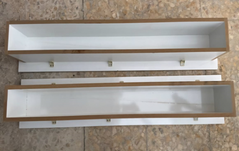
Table 4 reports the four mixing proportions used in this study. The procedure of storage and curing for the cubes was the same as that for the test beams. The beams and concrete cubes were covered with wet material and topped with plastic sheets to avoid moisture loss. Figure 3 shows the fibrous concrete mixing. The specimens were continuously moistened for 24 hours; after that, the beams were kept in the laboratory until testing. Wooden formworks are used in this study, as shown in Figure 4.
Table 4. Concrete mix details
|
Design Strength MPa |
Actual Strength MPa |
W/c |
Cement Kg/m3 |
Coarse Aggregate Kg/m3 |
Fine Aggregate Kg/m3 |
Superplasticizer Kg/m3 |
Steel Fiber % |
|
30 |
31 |
0.61 |
374 |
736 |
996 |
--- |
--- |
|
45 |
43 |
0.47 |
485 |
736 |
867 |
--- |
--- |
|
60 |
56 |
0.4 |
398 |
1097 |
635 |
6.4 |
--- |
|
58 |
55 |
0.45 |
410 |
1100 |
750 |
0.9 |
1 |
Figure 3. Fibrous concrete
Figure 4. Wooden form
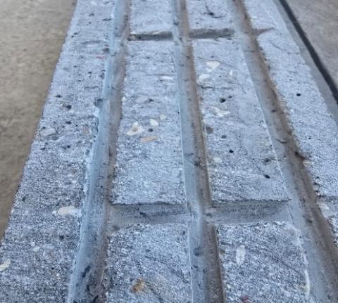
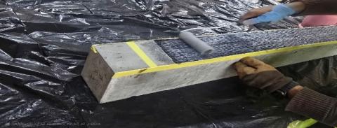
2.4 Strengthening procedure
Ten specimens were cast, one of which was used as the reference (without strengthening). However, the remaining nine specimens were strngthened CFRP, the concrete dough was scrubbed and removed from the beam surface using a grinder equipped with a specific disk, as preparation of the surface is essential for the effective application of CFRP, as shown in Figure 5. Water and compressed air were then used to clean the concrete surface in both EBR and EBROG strengthening processes. Longitudinal grooves, which run parallel to the beam axis, are used in the EBROG strengthening technique. The length of the groove was 900 mm, with an 8 mm width and a 6 mm depth. Conversely, transverse grooves, with dimensions with a length of 80 mm, a width of 8 mm, and a depth of 6 mm, were created perpendicular to the long axis of a beam in some of the specimens. Prior to applying the CFRP material, the grooves were cleaned using compressed air and water. Sikadur C330 epoxy resin was then used to apply CFRP sheets with a length of 950 mm and a width of 100 mm. As directed by the manufacturer, the beams were cured for 7 days. Figure 6 shows the details of the strengthening procedure.
Figure 5. Preparing specimen grooves for subsequent application of CFRP
Figure 6. Installation of CFRP by epoxy resin
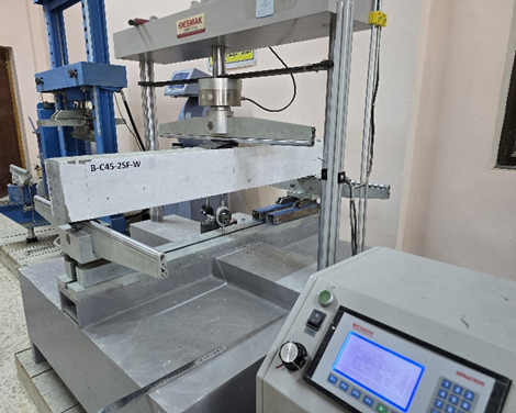
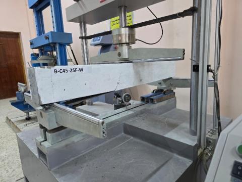
2.5 Test set-up and instrumentation
Each beam with a span of 1050 mm was tested under three-point loading. The crack propagation, mid-span deflection and maximum loads were noted throughout the testing procedure. A dial gauge positioned below the test specimen's tension face in the center of the beam was used to record the mid-span deflection. A 200 kN capacity machine with a steel frame was used to test all beams in flexure, as shown in Figure 7.
Figure 7. Testing machine
The deflections, loads, failure modes, and crack propagation of the CFRP-strengthened beams were examined.
3.1 Load–deflection curves
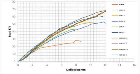
Figure 8 depicts the load versus deflection for all beams. From the results, we notice that if a specific point at a specific load is considered, for example, a load of 15 KN, we notice that the reference beam achieves a greater deflection than the beams reinforced with CFRP. The load versus deflection can be broadly categorized into three stages as follows: in the first stage, deflections are proportional to loads, and the load-deflection response is linear for beam specimens. The behavior is also linear in the second stage, although there are fewer gradients, which could be because cracking has started. In the final stage, the deflection increases significantly with little additional load. Table 5 reports a summary of the cracking and ultimate loads, and deflections at the cracking at failure level.
Figure 8. Load versus mid-span deflection curves for all tested beam
3.2 Cracking load
Table 5 reports the cracking load results for all beam specimens. It is clear from the table that as the concrete strength was increased, the applied load itself increased. Further, it was clear that the use of fibrous concrete in the tension zone led to an increased cracking load capacity. It was observed that the highest cracking load was 31 kN when using a 5 cm thick layer of fibrous concrete in the tension zone.
Table 5. Experimental results of beam specimens
|
Specimens |
Crack Load KN |
Percent Increase in Crack Load Capacity Compare With B-C45-R % |
Ultimate Load KN |
Percent Increase in Load Capacity Compare with B-C45-R % |
Ultimate Deflection mm |
Mode of Failure |
|
B-C45-R |
15 |
- |
28.70 |
0 |
12 8.71 |
Flexural |
|
B-C30-LG |
21 |
40.0 |
51.03 |
77.7 |
9.91 |
Concrete cover separation |
|
B-C45-LG |
25 |
66.7 |
54.79 |
90.9 |
10.26 |
Concrete cover separation |
|
B-C60-LG |
25 |
66.7 |
53.00 |
84.7 |
12.02 |
Concrete cover separation |
|
B-C45-2SF-LG |
26
|
73.3 |
66.80 |
132.7 |
12.88 |
Dependent on the cover separation |
|
B-C45-5SF-LG |
31 |
106.7 |
71.70 |
149.8 |
12.76 |
Rupture in CFRP |
|
B-C45-LTG |
23 |
53 |
61.10 |
112.9 |
11.25 |
Concrete cover separation |
|
B-C45-2SF-LTG |
28.8 |
92 |
68.70 |
139.4 |
13.33 |
Concrete cover separation |
|
B-C45-W |
20 |
33.3 |
43.50 |
51.6 |
8.7 |
Debonding of CFRP |
|
B-C45-2SF-W |
24 |
60 |
48.00 |
67.2 |
8.53 |
Debonding of CFRP |
3.3 Ultimate load and failure modes
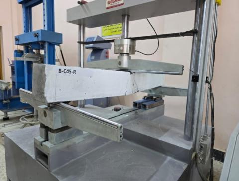
The effectiveness of the various strengthening methods was evaluated using a strengthened control beam as a reference specimen. The control beam's load–mid-span deflection curve is illustrated in Figure 9. The cracks evident were noted at 15 kN. As the load increased, the crack widths also expanded. With a final deflection of 8.1 mm at mid-span, the control beam subsequently collapsed due to flexure at a load of 28 kN. As can be seen in Figure 10, the failure was brought on by high flexural stresses around the central portion of the beam, which is where the maximum moment occurred.
Figure 9. Load versus deflection for B-C45-R
Figure 10. Failure mode for B-C45-R
Figure 11. Load versus deflection for B-C30-LG and B-C45-R
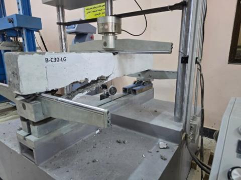
Figure 11 depicts the load versus deflection for beam B-C30-LG, which was strengthened by two layers of CFRP using three longitudinal grooves. The onset of cracking was observed at a load 21 kN, with the load increased by about 40% over the control beam, where the beam failed due to concrete cover separation as shown in Figure 12, followed by some critical cracks at mid-span when the load reached 51 kN, with a corresponding deflection of 11.12 mm. Despite the beam having a compressive strength that was lower than the control, the load was increased by about 77.7% over the control beam.
Figure 12. Failure mode for B-C30-LG
B-C45-LG: This beam strengthened by EBROG technique using two layers of CFRP sheet over longitudinal grooves, and a compressive strength of concrete of 45 MPa the test results showed the deflection to be 10.26 mm, with a first crack load of 25 kN, with a capacity increase of 67% and an additional increase in the capacity of 90.9% with regard to the reference beam, as shown in Figure 13. The failure mode was the concrete cover separation at a load of 54.79 kN, as shown in Figure 14.
Figure 13. Load versus deflection for B-C45-LG and B-C45-R
Figure 14. Failure mode for B-C45-LG
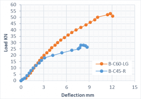
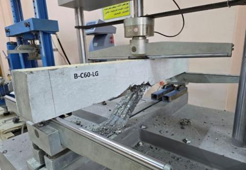
B-C60-LG: This beam was strengthened in the same manner as above beam sample using EBROG, with longitudinal grooves and double sheets of CFRP. Figure 15 shows the load deflection for the beam in comparison to the reference beam. A cracking load of 25 kN, representing an increase of 67%, a mid-span deflection of 12.02 mm, and a load-carrying capacity of 53 kN, representing an increase of 84.7% in comparison to the reference beam. The failure mode in this instance was debonding of the carbon fiber sheet from the concrete, as shown in Figure 16.
Figure 15. Load-deflection curve for B-C60-LG and B-C45-R
Figure 16. Failure mode for B-C60-LG
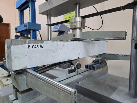
B-C45-W: This beam was strengthened using the EBR technique with double layers of CFRP. The load versus deflection for the beams tested (B-C45-W and B-C45-R) are presented in Figure 17. The cracking load was 20 KN, representing a 33% increase in comparison with the reference beam. The deflection was measured as 8.71 mm, and the load-carrying capacity was 43.5 kN; the beam failed due to carbon fiber debonding, as in Figure 18. The ultimate load was found to have increased by 51.5% in comparison to the control beam.
Figure 17. Load-deflection curve for B-C45-W and B-C45-R
Figure 18. Failure mode for B-C45-W
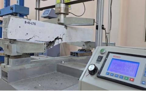
B-45-LTG: This beam is reinforced with double sheet CFRB using the EBROG technique, featuring eight transverse grooves and three longitudinal. The testing result gave a cracking load of 23 kN, representing an increase of 53%, while the load-carrying capacity achieved was 61.1 kN, representing an increase of 112.9% in comparison to the control beam. The deflection was 11.71 mm. Figure 19 illustrates the relationships between mid-span deflection and load for B-C45-LTG and B-C45-R. The failure mode involved cover separation from one side, as shown in Figure 20.
Figure 19. Load-deflection curve for B-C45-LTG and B-C45-R
Figure 20. Failure mode for B-C45-LTG
B-C45-2SF-LG: This beam strengthened as B-45-LTG, features a bottom layer formed from a different concrete (2 cm of fibrous concrete). The primary aim of this layer was to improve the bonding between the carbon fiber and the concrete face, much like the above beams that were strengthened using a double layer of carbon sheet with three longitudinal grooves. During testing, it was noted that the cracking load was 26 kN, representing an increase of 73% compared to the reference beam. The load achieved was 66.8 kN, representing an increase of 132.7%. compared with the reference beam, Figure 21 shows the load versus deflection, where the maximum deflection was 12.88, when this deflection compared to the B-C45-LG, showed an increase of 21.9%. The failure mode was debonding with cover separation, as depicted in Figure 22.
Figure 21. Load-deflection curve for B-C45-2SF-LG and B-C45-R
Figure 22. Failure mode for B-C45-2SF-LG
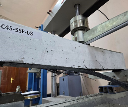
B-C45-5SF-LG: In this beam, the depth of the fibrous concrete layer was 5 cm, the purpose being to allow further assessment of the effect of depth on maximum load. The strengthening was achieved using a double layer of carbon fiber sheet on three longitudinal grooves. On testing, the cracking load was found to be 31 kN, representing an increase of 107% in comparison to the reference beam, while the max load was found to be 71.7 kN, a similar increase of 150%; Maximum mid-span deflection was 12.88 mm. This result was the greatest found for all strengthened beams. Figure 23 illustrates the load-midspan deflection relationship, with this particular beam showing a compound failure of rapture in the carbon fiber sheets and debonding in one side of beam as shown in Figure 24.
Figure 23. Load-deflection curve for B-C45-5SF-LG and B-C45-R
Figure 24. Failure mode for B-C45-5SF-LG
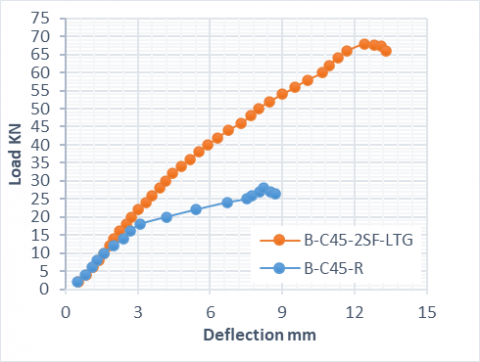
B-C45-2SF-LTG: This beam had both longitudinal and transverse grooves with a 2 cm depth of fibrous concrete as the bottom layer, after strengthening with double-sheet carbon fiber via EBROG. Figure 25 illustrates the mid-span deflection and load relationship for B-C45-2SF-LTG in relation to the reference beam. After testing, the cracking load was found to be 29 kN, representing a 92% increase in comparison to the reference beam. The maximum load was 68.7 kN, representing a 139% increase compared to the reference beam, with a maximum deflection of 13.33 mm. The beam failed due to debonding, with separation of the carbon fiber and some of the concrete cover, as shown in Figure 26.
Figure 25. Load-deflection curve for B-C45-2SF-LTG and B-C45-R
Figure 26. Failure mode for B-C45-2SF-LTG
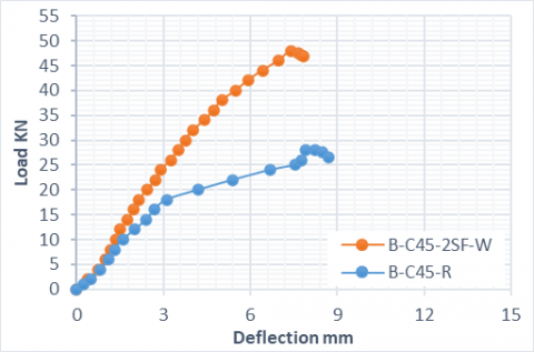
B-C45-2SF-W: This last beam was strengthened via EBR with a double sheet of carbon fiber. After testing, the results summarized in Figure 27 show load mid-span deflection response. The cracking load was 24 kN, which represented an increase of 60% in comparison with the reference beam. The load was 48 kN, an increase of 67.24% in comparison with the reference beam, with a dial gauge deflection of 8.53 mm. The failure mode was debonding in one direction, as per Figure 28.
Figure 27. Load-deflection curve for B-C45-2SF-W and B-C45-R
Figure 28. Failure mode for B-C45-2SF-W
3.4 Study variables
3.4.1 Strengthening method
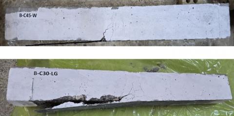
Two methods of strengthening, EBR and EBROG were examined to assess the improvement of flexural behavior achieved by each method. Table 4 shows the improvements in the strength of the beams strengthened via the EBR and EBROG methods ranged from 51.6% and from 90.9% to 112.9%, respectively. This improves that the EBROG approach is more advantageous than the EBR technique in terms of enhancing the behavior specimens. The results also showed that the use of transverse grooves increases the applied load and leads to a change in the failure pattern for beams strengthened via EBROG. It is clear that the EBROG method increased the flexural strength and the mode of failure changed the separation of the concrete cover or to the rupture of CFRP sheets instead of debonding. This could be because the EBROG technique increased the contact area between the CFRP and the concrete surface, which would have allowed for an increased bonding strength. Figure 29 shows the different modes of failure of the EBR and EBROG techniques.
Figure 29. Various modes of failure, here for B-C45-W and B-C30-LG
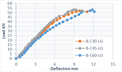
3.4.2 Influence of concrete compressive strength
Table 4 illustrates that increasing the compressive strength to a certain extent enhances the flexural strength of carbon fiber-reinforced beams under otherwise identical conditions. The results presented that the load increase between low and medium strength ranged from 77.7% to 90.9%, but which decreased to 84.7% when using high strength. This indicates that increasing the concrete strength enhances the bonding of the epoxy with the concrete particles, leading to a higher failure capacity, as shown in Figure 30.
Figure 30. Load-deflection curve for different compressive strengths, as strengthened by CFRP
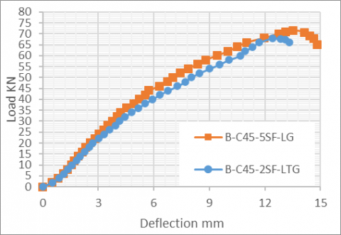
3.4.3 Effect of fibrous concrete layer in the tension zone
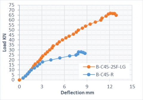
In this study, the bonding area was modified using fibrous concrete to investigate the effect of the type of concrete on the bond between the carbon fiber and the fibrous concrete (SFRC) surface. Table 4 shows that the specimens with a 2-cm-deep steel fiber-reinforced concrete layer exhibited higher strength under the same conditions than natural concrete. Specimens with a 5-cm-deep layer also achieved higher loads and greater deflection. This may be due to the epoxy particles effectively intermingling with the concrete and steel fibers, creating a high bond strength that reduces the likelihood of premature segregation. This result is consistent with previous results of shear strength [16]. Figure 31 shows the load-deflection curve for beams with different steel fiber reinforcement layers.
Figure 31. Load-deflection curve for B-C45-5SF-LG and B-C45-2SF-LTG
The study was conducted experimentally to evaluate the flexural characteristics of RC beams enhanced by CFRP strengthening, considering three compressive-strength values, in addition to studying the effects of replacement of the tension zone concrete with fibrous concrete (SFRC). Ten RC beams were tested to failure in their flexure mode, nine of which had been strengthened via the EBROG and EBR methods, with the tenth beam used as a control. The aim of the study was to evaluate the effects of the use of CFRP on the flexural behavior of RC beams with different compressive strengths, the effects of the type of concrete in the bonding zone, and to demonstrate the utility of the EBROG method. The main findings drawn from the study are as follows:
(1) In general, the load-carrying capability of the evaluated beams was significantly enhanced by both the EBR and EBROG procedures when using CFRP sheets.
(2) The flexural strength of beams with EBR and EBROG methods was found to increase by up to 51.6% and 122.9%, respectively. The higher flexural strength was achieved for beams strengthened via EBROG with transverse and longitudinal grooves.
(3) The effectiveness of the EBROG technical advancements as a reinforcing system is dependent on the number and direction of the grooves. Transverse grooves increase the ultimate load by increasing the bonded area between the concrete and CFRP.
(4) When the concrete strength was increased from 30 MPA to 45 MPa, the failure load increased from 77.7% to 90.9%, respectively. This indicates that increasing the concrete strength enhanced the bonding process and contributed to an increase in ultimate load. The cracking load also increased from 21 kN to 25 kN.
The addition of fibrous concrete (SFRC) to the tension zone (strengthening zone) improved deflection rates and increased maximum load values. The best strengthening effects were obtained when the depth of the steel-reinforced concrete layer was increased from 2 cm to 5 cm under otherwise identical conditions. It can be concluded that incorporating fibrous concrete in the tension zone of RC beams strengthened with CFRP using the EBROG technique has a positive influence on their flexural behavior.
|
CFRP |
carbon fiber reinforced polymer |
|
RC |
reinforced concrete |
|
EBR |
externally bonded reinforcement |
|
EBROG |
externally bonded reinforcement on grooves |
[1] El-Gamal, S.E., Al-Nuaimi, A., Al-Saidy, A., Al-Lawati, A. (2016). Efficiency of near surface mounted technique using fiber reinforced polymers for the flexural strengthening of RC beams. Construction and Building Materials, 118: 52-62. https://doi.org/10.1016/j.conbuildmat.2016.04.152
[2] Nguyen, D.M., Chan, T.K., Cheong, H.K. (2001). Brittle failure and bond development length of CFRP-concrete beams. Journal of Composites for Construction, 5(1): 12-17. https://doi.org/10.1061/(ASCE)1090-0268(2001)5:1(12)
[3] Li, J.L., Mai, Z.H., Xie, J.H., Lu, Z.Y. (2022). Durability of components of FRP-concrete bonded reinforcement systems exposed to chloride environments. Composite structures, 279: 114697. https://doi.org/10.1016/j.compstruct.2021.114697
[4] Massou, M., Babu, N., Xian, G.J. (2023). Experimental study on the mechanical properties of CFRP/epoxy composite plates under seawater immersion. Structures, 54: 48-57. https://doi.org/10.1016/j.istruc.2023.05.042
[5] Tatar, J., Milev, S. (2021). Durability of externally bonded fiber-reinforced polymer composites in concrete structures: A critical review. Polymers, 13(5): 765. https://doi.org/10.3390/polym13050765
[6] Aram, M.R., Czaderski, C., Motavalli, M. (2008). Debonding failure modes of flexural FRP-strengthened RC beams. Composite Part B: Engineering, 39(5): 826-841. https://doi.org/10.1016/j.compositesb.2007.10.006
[7] Moghaddas, A., Mostofinejad, D. (2019). Empirical FRP-concrete bond strength model for externally bonded reinforcement on grooves. Journal of Composites for Construction, 23(2): 04018080. https://doi.org/10.1061/(ASCE)CC.1943-5614.0000924
[8] Mostofinejad, D., Mahmoudabadi, E. (2010). Grooving as an alternative method of surface preparation to postpone debonding of FRP laminates in concrete beams. Journal of Composites for Construction, 14(6): 804-811. https://doi.org/10.1061/(ASCE)CC.1943-5614.0000117
[9] Hosseini, A., Mostofinejad, D. (2013). Experimental investigation into bond behavior of CFRP sheets attached to concrete using EBR and EBROG techniques. Composite Part B: Engineering, 51: 130-139. https://doi.org/10.1016/j.compositesb.2013.03.003
[10] Abed, R.J., Mashrei, M.A., Sultan, A.A. (2022). Flexural behavior of reinforced concrete beams strengthened by carbon fiber reinforced polymer using different strengthening techniques. Advances in Structural Engineering, 25(2): 355-373. https://doi.org/10.1177/13694332211049992
[11] Lu, X.Z., Teng, J.G., Ye, L.P., Jiang, J.J. (2005). Bond–slip models for FRP sheets/plates bonded to concrete. Engineering Structures, 27(6): 920-937. https://doi.org/10.1016/j.engstruct.2005.01.014
[12] Mashrei, M., Makki, J., Sultan, A.A. (2019). Flexural strengthening of reinforced concrete beams using carbon fiber reinforced polymer (CFRP) sheets with grooves. Latin American Journal of Solids and Structures, 16(4): e176. https://doi.org/10.1590/1679-78255514
[13] Mostofinejad, D., Hajrasouliha, M.J. (2013). Effect of concrete strength and groove dimension on performance of grooving method to postpone debonding of FRP sheets in strengthened concrete beams. IJST, Transactions of Civil Engineering, 37(C2): 219-232.
[14] Mostofinejad, D., Mofrad, M.H., Hosseini, A., Mofrad, H.H. (2018). Investigating the effects of concrete compressive strength, CFRP thickness and groove depth on CFRP-concrete bond strength of EBROG joints. Construction and Building Materials, 189: 323-337. https://doi.org/10.1016/j.conbuildmat.2018.08.203
[15] Al-zu’bi, H., Abdel-Jaber, M., Katkhuda, H. (2022). Flexural strengthening of reinforced concrete beams with variable compressive strength using near-surface mounted carbon-fiber-reinforced polymer strips [NSM-CFRP]. Fibers, 10(10): 86. https://doi.org/10.3390/fib10100086
[16] Ouda, M.A., Mashrei, M.A. (2022). Shear strength of steel fibrous concrete beams strengthened by CFRP using various techniques. Structures, 38: 519-535. https://doi.org/10.1016/j.istruc.2022.02.027
[17] Duhaim, H.M., Mashrei, M.A. (2022). Stress-strain relationship of ductile materials and flexural behavior of ductile over-reinforced concrete beams. Scientific Review Engineering and Environmental Sciences, 31(4): 225-237. https://doi.org/10.22630/srees.4253
[18] ASTM International. (2010). ASTM C33/C33M: standard specification for concrete aggregates. West Conshohocken, PA: ASTM International. https://doi.org/10.1520/C0033_C0033M-08
[19] ASTM C150/C150M. (2019). Standard specification for portland cement. ASTM International, West Conshohocken, https://www.astm.org/c0150_c0150m-19.html.
[20] American Association of State Highway and Transportation Officials (AASHTO). (2004). Standard specification for deformed and plain carbon steel bars for concrete reinforcement. American Association of State Highway and Transportation Officials. https://transportation.org/materials-guidelines.