Husam Jawad Ali*![]() | Diyah Kammel Shary
| Diyah Kammel Shary![]() | Bayadir A. Issa
| Bayadir A. Issa![]()
© 2025 The authors. This article is published by IIETA and is licensed under the CC BY 4.0 license (http://creativecommons.org/licenses/by/4.0/).
OPEN ACCESS
This study presents an intelligent speed control model for Separately Excited DC motors (SEDCM), consisting of three main steps. The first step follows a conventional Proportional-Integral-Derivative (PID) controller, which typically controls the speed under varying load conditions. The second step applies improved PID controller performance through optimization algorithms such as Particle Swarm Optimization (PSO) and Grey Wolf Optimization (GWO) to fine-tune PID parameters more precisely. The third step uses an intelligent, internet-connected Artificial Neural Network (ANN)-based controller capable of effectively handling any operating condition, as well as motor parameters. This novel approach utilizes artificial intelligence techniques and optimization algorithms to improve the efficiency of SEDCM speed control. Among existing control approaches, ANNs excel at learning from training data and self-tuning under changing operating conditions. Simulation results confirm the internet-connected ANN controller's superiority over conventional and optimization-based PID controllers in terms of efficiency and accuracy. These findings establish the abilities of ANNs to optimize instantly while ensuring true dynamic feedback for control applications.
Artificial Neural Network (ANN), Grey Wolf Optimization (GWO), Proportional-Integral-Derivative (PID) controller, Particle Swarm Optimization (PSO), Separately Excited DC Motor (SEDC)
According to this study, a novel idea of Artificial Neural Networks (ANNs) for speed estimation and control of discretely stimulated DC motors is introduced via motor voltage control in conjunction with artificial intelligence approaches [1]. ANNs, MATLAB, and Simulink tools are some of the most significant contemporary technologies for control applications. Simulation results show how reliable neural network-based speed controllers are. Better dynamic performance, shorter rise times, and less overshoot and undershoot are the outcomes of neural network speed controllers [2]. This study explores voltage regulation-based speed control using conventional techniques, such as Proportional-Integral-Derivative (PID), and innovative approaches, such as ANN and nature-inspired optimization algorithms. It is crucial to keep in mind that the maximum voltage permitted limits the highest speed that can be attained using motor voltage management techniques [3]. The recommended techniques are applied in designing and implementing a speed controller to control the speed of a DC motor that is stimulated separately. The PID type speed controller, which reduces steady-state error and offers quick control, is used to regulate the speed of the Separately Excited DC motor (SEDCM) to its maximum rated speed [4]. In many applications, speed control is essential to achieving desired levels of operation. Field current control and motor voltage control are two basic techniques. The performance of PID controllers, which use motor voltage control technology to control speed, is compared. Utilizing existing literature, such as the application of fuzzy logic controllers to regulate the operations of DC motors, the study extends the scope of previous research. The researchers demonstrated the benefits of axiomatic logic-based controllers by applying fuzzy logic controllers and ANFIS and comparing them with conventional proportional-integral-differential controllers. Furthermore, investigations into the use of ANN to speed up estimation and control revealed accurate control and effective operation [5].
In 1991, Weerasooriya and El-Sharkawi [6] presented a high-performance speed-control system for a DC motor based on ANNs is presented. It is possible to set the DC motor's rotor speed to follow any chosen path. Accurate trajectory control of the speed is the goal, particularly in situations where the load and motor parameters are unknown. The ANN captures the unknown nonlinear dynamics of the load and the motor. To accomplish trajectory control of speed, a desired reference model is paired with the trained neural network identification. By simulating the identification and control algorithms on a standard DC motor model, their performances are assessed. It is demonstrated that an ANN can effectively regulate a DC motor. [6]. In 2017, Alhanjouri [7] estimated and controlled an SEDCM using ANNs. This method is one of the most important contemporary methods for increasing the control efficiency of SEDCM, and control applications. The rotor speed of a DC motor can be adjusted to follow a randomly selected path. The goal is to achieve precise speed trajectory control, especially in cases where load and motor parameters are unknown. The Levenberg-Marquardt backpropagation algorithm is used to train the model. By comparing the system with a conventional proportional-integral controller, simulation results demonstrate the benefits, effectiveness, and performance of ANN controllers. Consequently, the results demonstrate that ANN approaches provide accurate control and optimal performance in real-time [7, 8].
Mahmood et al. [9] presented a high-performance speed controller designed for discretely excited DC motor SEDCM applications in high-power, for instance, traction electric in naval vessels and air vehicles. The controller modifies the motor terminal voltage using a reference voltage that is generated based on estimated speed, which is estimated by a neural network. To control the motor speed, the authors put forward a three-layer neural network, which had superior performance compared to regular control models in speed regulation and response accuracy. The results indicate that neural networks can be used to effectively control dynamic speed in complex systems.
In 2024, Prasad et al. [10] suggested a Neural Network Predictive Controller (NNPC) based on deep learning (DL) for accurate DC motor speed control. Based on the motor's current condition and control inputs, the controller forecasts how the motor will behave in the future. After that, the controller produces inputs in the best possible way to lower tracking mistakes and enhance system performance. These numerical findings validate the suggested predictive controller's dependability and resilience for DC motor system speed control in a variety of applications.
In 2021, Dutta and Nayak [11] introduced the Grey Wolf Optimization (GWO) method for optimizing the parameters of traditional PID controllers. They stated that real-time parameter adjustment is one of the problems with PID controllers. The Particle Swarm Optimization (PSO) algorithm has been shown in recent research to be effective in fine-tuning the PID controller for brushless DC motors; however, GWO provides an enhanced alternative. With better dynamic performance and reactivity to shifting operating conditions, the GWO algorithm was proven to perform better than the PSO approach when used in PID tuning. This demonstrates that when compared to traditional optimization techniques, the suggested GWO-based strategy provides better performance [11, 12].
Hatta et al. [13] presented the GWO as a method for obtaining, optimizing, and finding the best possible solution to a given problem, regardless of its constraints. This algorithm adopts the hierarchical nature of gray wolves, their leadership structure, and their natural hunting behavior. The algorithm ranks the best solutions, and its search method-tracking, encircling, and attacking-is mathematically designed to find the best optimized solution. The characteristics of GWO, used in many problems, are discussed, such as parameter tuning and how it mitigates problems in different applications.
However, despite the widespread use of traditional control methods, such as PID, PSO, and GWO, these methods barely meet the requirements of high accuracy and dynamic adjustment in highly volatile systems. Considerable efforts have been made to apply limited integration of ANNs to remove limitations and increase the effectiveness of speed control in SEDCMs. This study seeks to address this shortcoming with online ANN-based controllers, which offer real-time adaptation, increased accuracy, and improved performance compared to traditional control methods. The use of direct back-propagation neural networks for real-time control of motor voltage improves system response and accuracy and represents a promising solution for contemporary speed control applications.
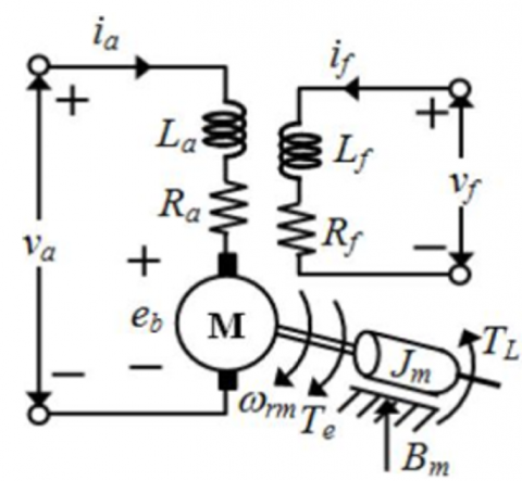
The corresponding circuit of a DC motor with separate excitation is depicted in Figure 1 [14].
Figure 1. Equivalent circuit of SEDCM [15]
The electromagnetic equations of the system can be used to determine the dynamic behavior of DC motors, and the following equations govern the field and armature voltages [15]:
$V_a=\left(r_a+\frac{d L_a}{d t}\right) i_a+\omega_r L_{a f} i_a$ (1)
$V_f=\left(r_f+\left(d L_a\right) / d t\right) i_a$ (2)
where, the self-resistance of the field winding $r_f$, the armature winding $r_a$, along with their respective self-inductances $L_f$, for the field and $L_a$ for the armature, the currents flowing through the field $i_f$ and armature windings $i_a$, the rotor speed $\omega_r$, and the mutual inductance between the field and armature windings $L_{a f}$, all contribute to determining the electromagnetic torque $T_e$.
$V_f=\left(r_f+\left(d L_a\right) / d t\right) i_a$ (3)
The relationship between load torque (TL) and electromagnetic torque is as follows [15]:
$T_e=J\left(\frac{d w_r}{d t}\right)+B w_r+T_L$ (4)
where, J is the rotor's inertia plus any mechanical load that is connected. B represents the dampening coefficient related to the machine's mechanical rotation mechanism.
3.1 Using PID-controller
Conventional PID controllers have been the control method of choice for numerous industrial processes and motor control applications. The currently used trial-and-error method to adjust the controller parameters is time-consuming and labor-intensive. Although the PID control technique is simple and reliable, increasing the gain of the PID controller remains a challenging task [15]. Figure 2 shows the structure of the controller PID [12].
Figure 2. Traditional PID controller [8]
$U(t)=k_p e(t)+k_i \int e(t) d t+k_d \frac{d}{d t} e(t)$ (5)
The time-dependent error signal, or the control output, is represented by the control signal, $U(t)$. The input signal of a PID controller, $e(t)$, is also known as the error signal, as it is used to determine how much deviation exists between the desired data input and actual output value. The full impact of each controller parameter ($k_p$, $k_i$, $k_d$) on a typical closed-loop system is crucial to achieving optimal voltage regulation. In this study, tuning these parameters is a key focus to enhance the speed control performance of SEDCM, ensuring improved dynamic response and stability [16]. The objective function is initially constructed by taking the intended specifications and limitations into account before designing the PID controller using an optimization technique. An appropriate objective function is selected to adjust the controller parameters from two groups: (a) criteria based on the complete response or integrated criteria, and (b) criteria based on a few selected areas in the response. The Squared Error Integral (ISE), Eq. (6), was generally chosen because of its good performance in meeting the requirements of this study. The total of the squares of the variations between the reference signal (or desired value) and the actual system response over a given period is determined by the integral of the squared error. This helps to reduce long-term errors and ensures that the system behaves in a stable and well-controlled manner throughout the entire response period [11, 12, 17]:
$I S E=\int e^2(t) d t$ (6)
where, ISE is the integral square error objective value, and $e(t)$ is a measurement of the error of the measured process output variable as compared to a desired set point.
3.2 PSO algorithm
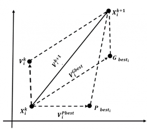
PSO is an ensemble-based evolutionary algorithm, initially developed by Eberhardt and Kennedy. PSO is designed to optimize continuous nonlinear functions. A notable advantage of PSO is its ease of implementation and the lack of gradient information [18]. PSO can be used to solve a range of optimization problems. As with other evolutionary algorithms, the PSO algorithm searches a population of particles, one of which might represent a candidate solution to the problem at hand. The particles move through the multidimensional search space until their computational budget is exhausted. The PSO algorithm used to update the particles is given by Eqs. (7)-(8). The PID controller proposed and developed here, as shown in Figure 3, has also been optimized using the PSO algorithm [16]. It is worth noting that the PSO algorithm is used to fine-tune the PID parameters by simulating a population of particles searching the parameter space for optimal values. The position and velocity parameters of the particles are updated based on past experiences to find the best solution. Its parameters are set with an inertia weight of 0.9, a perception coefficient of 2, and a social coefficient of 1.5. Convergence occurs when, after several generations, performance reaches a satisfactory level or no significant progress is achieved.
Figure 3. PSO algorithm
$V_i^{k+1}=w_t v_i^k+c_1 r\left[P_{{best }}^k-X_i^k\right]+c_2 r_2\left[G_{ {best }}^k-X_i^k\right]$ (7)
$X_i^{k+1}=X_i^k+V_i^{k+1}$ (8)
where, $V_i^{k+1}$ is the velocity of the ith particle at iteration $k$. The position of the ith particle at iteration $k$ is a particular particle’s personal best position, which is the best location found in the time interval [0, t]; $c_1$ and $c_2$ are cognitive and social factors, respectively are random coefficients, and $w_t$ is the inertia weight [16].
However, the PSO algorithm simulates optimization of PID parameters by simulating a population of particles searching the parameter space to determine optimal values. Particle velocity and position parameters are adjusted based on experience with possible optimal solutions. This method maximizes control performance by minimizing errors and improving dynamic response. Convergence is achieved when performance is within a satisfactory range or when no further improvements are observed after several generations. The PSO algorithm does not include gradient information and can therefore be used for complex, nonlinear problems.
3.3 GWO algorithm
Mirjalili et al. [19] described the improvement of the grey wolf’s optimization. The social hierarchies will be shown in Figure 4.
Figure 4. Grey wolf hierarchy [20]
In the wolf hierarchy, there are three dominant types: Alpha ($\alpha$), Beta ($\beta$), and Delta ($\beta$), which lead and dominate the Omega ($omega$) wolves. The pack is further organized into specific roles, including scouts, guards, elders, hunters, and caretakers. Scouts keep an eye on the territory's borders and warn the pack of any threats. Caretakers ensure the safety of all members within the pack. Hunters assist Alpha and Beta wolves in gathering food and hunting prey. Wolves that are weak, ill, or injured must be cared for by caregivers. This hierarchy forms the basis of the wolf’s hunting mechanism (algorithm), which is used to locate and pursue prey (i.e., the resolution or decision). The hunting process consists of three basic steps [17]:
1. Following, tracking, and approaching the victim.
2. Disrupting the prey to prevent it from moving and turning around it to ensure a successful hunt.
3. It is forceful to take the prey.
Figure 5 shows the flowchart for detecting and updating parameter usage.
Figure 5. GWO algorithm flowchart [17]
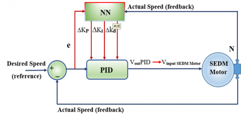
3.4 Online neural network-based PID controller design
Online Neural Networks (NNs) are used to change the parameters of input and output. Backpropagation (BP) learning networks are one method for training this. The results of simulations and experiments show that the suggested controller is reliable and effective in controlling SEDCM speed, according to modeling and experimental data [21, 22]. The proposed controller leverages a neural network to optimize the parameters of a conventional controller. This involves performing a detailed analysis, during which the controller output (the voltage that powers the motor) is modified. After determining the parameters of the conventional controller, appropriate values are set to ensure stable operation of the motor. This process is designed to maintain the desired motor speed and match it to the intended output across a range of load conditions and operating techniques, regardless of variations in load or operating time. The ANN controller's construction is depicted in Figure 6 [17].
Figure 6. Structure of NN [17]
The controller in question recognizes inputs as well as outputs listed below:
$X_i=\left[\begin{array}{l}e \\ N\end{array}\right]$ (9)
$y_o=\left[\begin{array}{l}K_P \\ K i \\ k d\end{array}\right]$ (10)
where, $X_i$: The input vector is equivalent to the neural network controller's input vector. A neural network controller's output vector, represented by the symbol $y_0$ [23], is crucial to ensuring the overall operating efficiency of the system shown in Figure 7.
Figure 7. Block schematic of a separately DC motor by a neural network [17]
The proposed controller uses the PID neuron controller, as shown in Figure 8, to modify the output parameters.
Figure 8. The neural-PID controller constructed using a MATLAB model
The algorithm structure of the BPA learning system is illustrated in Figure 9 with the help of a flow chart. In this flow chart, the input data ($x_i$) is provided in the form of a vector consisting of some rows equal to $S$ and some columns equal to the number of input neurons. In contrast, the target output data ($d$) is represented as a column vector with S rows.
Figure 9. Flow chart of the backpropagation training [12, 24]
The PID controller should be adjusted according to the motor requirements, and a trial-and-error method was used in this test. The motor specifications are shown in Table 1. Figure 10 shows the response of speed control of the SEDC motor without a PID controller (uncontrolled).
Table 1. Parameter specifications for the proposed motors [25]
|
Motor Parameters |
Symbol |
Value |
Unit |
|
Field inductance |
Lf |
0.167 |
H |
|
Armature inductance |
La |
0.1215 |
H |
|
Mutual inductance |
Laf |
0.004 |
H |
|
Armature resistance |
ra |
11.2 |
Ω |
|
Field resistance |
rf |
1.43 |
Ω |
|
Armature voltage |
Va |
240 |
V |
|
Field voltage |
Vf |
12 |
V |
|
Rotor inertia |
J |
0.02215 |
kg.m2 |
|
Friction coefficient |
B |
0.002953 |
N.m.s/rad |
|
Torque constant |
Kt |
1.28 |
N.m/A |
|
Torque constant |
ke |
0.167 |
V.Sec/rad |
|
Load torque |
TL |
0.1215 |
N.m |
|
desired speed |
N |
1500 |
rpm |
Figure 10. Uncontrolled DC motor speed response of SEDC
The controlled plant in this paper is an SEDC motor. Figures 11 and 12 show the block diagram for the SEDC motor speed control system using a PID controller.
Figure 11. A model of an SEDCM using transfer function blocks in Simulink (uncontrolled) [14]
Figure 12. Block diagram for the SEDC motor’s overall modeling (controlled)
MATLAB R2020a was used to simulate the SEDC motor. The PID controller parameters were determined through trial and error, and Table 2 also presents the settings of the conventional controller.
Table 2. Parameters for PID controller
|
Algorithm |
KP |
KI |
KD |
|
PID |
350 |
83 |
50.49 |
Figure 13 illustrates the speed control response of the SEDC motor using a PID controller. When first introduced to industrial applications in 1939, PID controllers lacked optimization algorithms and methods yet quickly became popular due to their simplicity and effectiveness. The presented plots demonstrate the outcomes of applying conventional PID control to a separately excited DC (SEDC) motor. These plots specifically depict the closed-loop speed response when the PID controller is utilized for speed regulation. As shown in Figure 13, the motor speed rises from 0 to a peak of 1504 rpm during start-up, followed by a slight drop to 1501 rpm upon applying a 10 Nm load torque (full load) at the 10-second mark [12].
Figure 13. Speed control response of the SEDC motor using a PID controller
Additionally, PSO is utilized to identify the optimal parameters of PID controllers for achieving precise motor speed control. The process requirements and PID controller parameters optimized with PSO are compiled in Tables 3 and 4.
Table 3. Parameter values of basic algorithms
|
All Algorithms [PSO and GWO] |
Value |
|
Maximum Search Agents |
50 |
|
Repeated Iterations |
20 |
Table 4. Parameters for PSO-algorithm
|
Algorithm |
KP |
KI |
KD |
|
PSO |
360 |
85 |
45.45 |
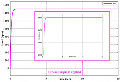
Figure 14 shows the response of speed control of the SEDC motor with the PSO algorithm. The graphs displayed here show the motor speed attained by optimizing the parameters of the traditional PID controller for speed regulation in SEDC motors using the PSO method. As shown in Figure 14, the speed remains steady at 1500 rpm during the start-up phase. When a load torque of 10 N.m (maximum load) is applied for 10 seconds, no speed drop is observed, and the motor remains at 1500 rpm.
Figure 14. The response of speed control of SEDC motor - PSO algorithms
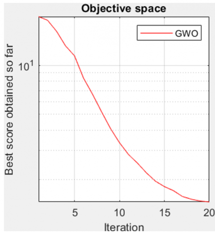
Figure 15 shows the convergence curve of the algorithm with iteration.
Figure 15. Convergence curve of the algorithm over iteration
Table 5 outlines the details and key specifications of the GWO algorithm.
Table 5. Parameters for GWO-algorithm
|
Algorithm |
KP |
KI |
KD |
|
GWO |
367 |
86 |
46 |
Figure 16 illustrates the speed control response of the SEDC motor using the GWO algorithm. Comparative tests conducted under identical conditions with a standard PID controller and the GWO-optimized controller reveal that the GWO algorithm effectively identifies the PID controller's ideal speed control parameters without changing the motor speed. Motor speed regulation and torque feedback were significantly improved by using the GWO method to optimize the PID controller. As shown in Figure 16, during the startup phase, the motor speed remains steady, reaching a maximum of 1500 rpm. The motor maintains a steady speed of 1500 rpm when a load torque of 10 Nm (maximum load) is applied for 10 seconds, improving speed regulation by about 99.99% when compared to a typical PID controller. The difference between the desired and achieved speeds disappears.
Figure 16. Speed control response of the SEDC motor using the GWO algorithm
Figures 17 (a) and (b) show the convergence curve of the algorithm with iteration.
This study focuses on optimizing a PID controller by integrating a neural network to develop an advanced speed controller. Simulations were performed in MATLAB using the data provided in the tables. In addition to improving performance, the neural network created using this method provides a more effective speed regulation control mechanism. This enhancement shows how the neural network approach may improve motor efficiency, precisely control several operational parameters, and greatly improve system performance. According to Simulink statistics, the neural network approach performs noticeably better than the conventional PID controller, enhancing motor speed stability and guaranteeing more seamless operation. A dataset of inputs and their associated outputs is needed for algorithms like backpropagation, which are employed in neural networks to learn the links between inputs and outputs. During training, the network adjusts its internal weights and parameters in a manner that minimizes the difference between the desired and predicted outputs. In this work, the optimized weight values and equations obtained by training are provided, as shown below. The tuned weights play a significant role in improving the performance of the neural network to regulate motor speed and adapt to changing system conditions, leading to improved stability and control accuracy. With new input data, the neural network can predict system behavior in post-training simulations [7, 12, 17, 22].
The following equations can be used to calculate the mathematical expression defining the neural network, as per scholarly conventions [12, 23, 24, 26].
(a)
(b)
Figure 17. GWO search space and pattern of search
$S_j^k=\sum_{i=1}^n W_{j i}^k \cdot X_i^k+b_j^k$ (11)
$y_j^k=\frac{1}{1+e^{-S_j^k}}$ (12)
$S_0^k=\sum_{j=1}^k W_{0 j}^k . y_i^k+b_0^k$ (13)
$y_0^k=\frac{1}{1+e^{-S_0^k}}$ (14)
where,
The output of the hidden layers is represented as $y_j^k$.
The outputs of the neural network are represented as $y_o^k$.
$W_{j i}$ is the weight of the input neurons to those neurons that are hidden.
$W_{o j}$ is the weight-to-output ratio of hidden neurons.
$b_j^k$ is the concealed layers' bias.
$b_o^k$ is the output layers' bias.
K is the training set and K = 1:S
S is the total number of training sets.
The parameters of neural networks are as follows:
The following weights are found in the hidden layer:
$W_{j i}=\left[\begin{array}{l}0.0981 ; 8.3681 \\ 0.2807 ; 7.3165 \\ 0.5491 ; 6.6357 \\ 0.9578 ; 8.1126 \\ 0.9661 ; 6.7686\end{array}\right] ; h_j=\left[\begin{array}{l}8.3404 \\ 6.7652 \\ 6.5860 \\ 8.4154 \\ 6.9203\end{array}\right]$
Weights of output layers:
$\begin{gathered}W_{0 j}=\left[\begin{array}{c}4.4548 ; 5.3611 ; 6.6078 ; 6.1310 ; 6.3472 \\ 2.9305 ; 3.0235 ; 3.4087 ; 2.7614 ; 3.4326 \\ 2.6306 ; 2.4944 ; 2.5736 ; 3.2655 ; 3.1662\end{array}\right] \\ h_o=\left[\begin{array}{l}7.4066 \\ 3.0332 \\ 2.8529\end{array}\right]\end{gathered}$
The speed is then increased by connecting the neural network and PID controller. The ability of neural networks to manage complex, nonlinear systems makes them effective tools for modeling and control. The basic features and specifications of the ANNs used in this work are illustrated in Table 6 and Figure 18.
Table 6. Parameters for ANN-algorithm
|
Algorithm |
KP |
KI |
KD |
|
ANN |
330 |
35.11 |
10 |
Figure 18. Speed control response of the SEDC motor using the ANN algorithm
4.1 Comparison of speed control performance: PID, PSO, GWO, and ANN algorithms
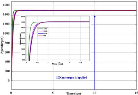
The SEDC motor's speed responses for the four approaches are depicted in Figure 19, and the motor's performance using the aforementioned procedures is displayed in Table 7.
Figure 19. Comparison of speed responses for PID, PSO, GWO, and ANN controllers
Table 7. Shows the performance values of the four methods
|
Algorithm |
Rise Time (sec) |
Overshoot (%) |
Settling Time (sec) |
|
PID |
0.3099 |
0.2302 |
0.5399 |
|
PSO |
0.2732 |
0 |
0.4869 |
|
GWO |
0.2330 |
0 |
0.4286 |
|
ANN |
0.0998 |
0 |
0.1752 |
Many optimization problems can be solved using the PSO method. Like other evolutionary algorithms, this method searches a population of particles, each representing a unique solution to the problem at hand. In PSO, the particles move through a multidimensional search space until computational constraints are met, allowing for necessary adjustments.
The third method, based on a PID controller optimized using the GWO algorithm, outperforms the previous method in response time. However, it responds more slowly than the next method. The fourth method, which uses an ANN-based PID controller connected to the internet, provides the most efficient response in terms of motor speed control. The ANN-based PID controller ensures a constant motor speed in real time and demonstrates its ability to effectively handle sudden speed changes, ensuring stable and reliable motor performance. When compared to the previous three controllers, the online ANN-based PID controller demonstrates significant improvement, achieving a 100% increase in overall performance and motor speed regulation efficiency.
Numerous factors determine the best way to regulate an SEDC motor's speed, including:
• If it requires a straightforward, proven control technique that reacts fast to modifications in the intended application, PID controls may be the best option.
• GWO is a great option if you want to minimize implementation effort while simultaneously optimizing and fine-tuning settings.
• If a system's behavior is complicated and non-linear and there is enough training data available, ANN can improve its performance and adaptability.
The gap between traditional PID controllers and PSO, GWO, and ANN algorithm-tuned controllers continues to have improved performance in most fields. Traditional PID controllers have been limited in power control and flexibility in managing long-term parameter variations. Though PSO and GWO algorithms improve grid flexibility, energy efficiency, and efficiency, they are more efficient. ANNs strive to lead in providing long-term, accurate stability in fluctuating electronics and non-coordination, thus the ideal option to invest in complex applications.
|
B |
damping coefficient, Ns/rad./sec |
|
E |
electromagnetic force, V |
|
i |
current, A |
|
j |
inertia, Kg.m2 |
|
K |
constant |
|
L |
inductance, H |
|
R |
resistance, W |
|
T |
torque, N.m. |
|
V |
voltage, V |
|
Greek symbols |
|
|
w |
speed, rad./sec |
|
Subscripts |
|
|
a |
armature |
|
b |
back |
|
D |
derivative |
|
e |
electromagnetic |
|
I |
integral |
|
L |
load |
|
P |
proportional |
|
t |
torque |
|
v |
velocity |
[1] El Hamidi, K., Mjahed, M., El Kari, A., Ayad, H. (2020). Adaptive control using neural networks and approximate models for nonlinear dynamic systems. Modelling and Simulation in Engineering, 2020(1): 8642915. https://doi.org/10.1155/2020/8642915
[2] Elnaghi, B.E. (2023). Experimental validation of neural network speed controller of induction motor. In 2023 24th International Middle East Power System Conference (MEPCON), Mansoura, Egypt, pp. 1-6. https://doi.org/10.1109/MEPCON58725.2023.10462365
[3] Ho, T.Y., Chen, Y.J., Chen, P.H., Hu, P.C. (2017). The design of a motor drive based on neural network. In 2017 International Conference on Applied System Innovation (ICASI), Sapporo, Japan, pp. 337-340. https://doi.org/10.1109/ICASI.2017.7988421
[4] Sahana, M., Angadi, S., Raju, A.B. (2016). Speed control of separately excited dc motor using class a chopper. In 2016 International Conference on Circuits, Controls, Communications and Computing (I4C), Bangalore, India, pp. 1-6. https://doi.org/10.1109/CIMCA.2016.8053296
[5] Timothy, I. (2024). Bridging the gap: Classical vs. intelligent controllers for separately excited DC motor speed management. Journal of Climate Science and Meteorology, 1(1): 11-22. https://doi.org/10.5281/zenodo.8234154
[6] Weerasooriya, S., El-Sharkawi, M.A. (1991). Identification and control of a DC motor using back-propagation neural networks. IEEE transactions on Energy Conversion, 6(4): 663-669. https://doi.org/10.1109/60.103639
[7] Alhanjouri, M. (2017). Speed control of DC motor using artificial neural network. International Journal of Science and Research, 7(3): 2140-2148. https://doi.org/10.21275/ART20172035
[8] Dzung, P.Q. (2005). Control system DC motor with speed estimator by neural networks. In 2005 International Conference on Power Electronics and Drives Systems, Kuala Lumpur, Malaysia, pp. 1030-1035. https://doi.org/10.1109/PEDS.2005.1619839
[9] Mahmood, Z.S., Nasret, A.N., Mahmood, O.T. (2021). Separately excited DC motor speed using ANN neural network. AIP Conference Proceedings, 2404(1). https://doi.org/10.1063/5.0068893
[10] Prasad, B., Kumar, R., Singh, M. (2024). Analysis of DC motor for process control application using neural network predictive controller. Engineering Research Express, 6(2): 025004. https://doi.org/10.1088/2631-8695/ad3b66
[11] Dutta, P., Nayak, S.K. (2021). Grey wolf optimizer based PID controller for speed control of BLDC motor. Journal of Electrical Engineering & Technology, 16: 955-961. https://doi.org/10.1007/s42835-021-00660-5
[12] Ali, H.J. (2024). Intelligent techniques based speed control of brushless DC motor (BLDCM). Basrah Engineering Technical College, Southern Technical University, p. 68.
[13] Hatta, N.M., Zain, A.M., Sallehuddin, R., Shayfull, Z., Yusoff, Y. (2019). Recent studies on optimisation method of Grey Wolf Optimiser (GWO): A review (2014-2017). Artificial Intelligence Review, 52: 2651-2683. https://doi.org/10.1007/s10462-018-9634-2
[14] Sami, S.S., Obaid, Z.A., Muhssin, M.T., Hussain, A.N. (2021). Detailed modelling and simulation of different DC motor types for research and educational purposes. International Journal of Power Electronics and Drive Systems, 12(2): 703-714. https://doi.org/10.11591/ijpeds.v12.i2.pp703-714
[15] Pal, P., Dey, R., Biswas, R.K., Bhakta, S. (2015). Optimal PID controller design for speed control of a separately excited DC motor: A firefly based optimization approach. International Journal of Soft Computing, Mathematics and Control, 4(4). https://doi.org/10.2139/ssrn.3517152
[16] Shary, D.K., Nekad, H.J., Alawan, M.A. (2023). Speed control of brushless DC motors using (conventional, heuristic, and intelligent) methods-based PID controllers. Indonesian Journal of Electrical Engineering and Computer Science, 30(3): 1359-1368. https://doi.org/10.11591/ijeecs.v30.i3.pp1359-1368
[17] Ali, H.J., Shary, D.K., Abbood, H.D. (2024). A review of intelligent techniques based speed control of brushless DC motor (BLDC). Basrah Journal for Engineering Sciences, 24(1): 109-119. https://doi.org/10.33971/bjes.24.1.12
[18] Okwu, M.O., Tartibu, L.K. (2020). Metaheuristic Optimization: Nature-Inspired Algorithms Swarm and Computational Intelligence, Theory and Applications. Springer Nature, UK.
[19] Mirjalili, S., Mirjalili, S.M., Lewis, A. (2014). Grey wolf optimizer. Advances in Engineering Software, 69: 46-61. https://doi.org/10.1016/j.advengsoft.2013.12.007
[20] Yang, B., Zhang, X., Yu, T., Shu, H., Fang, Z. (2017). Grouped grey wolf optimizer for maximum power point tracking of doubly-fed induction generator based wind turbine. Energy Conversion and Management, 133: 427-443. https://doi.org/10.1016/j.enconman.2016.10.062
[21] Hassan, F.N., Fayek, W.M., Seoudy, H.M., Kamel, A. (2013). Speed regulation of brushless DC drives using optimized fuzzy logic controller. In International Conference on Aerospace Sciences and Aviation Technology, pp. 1-13. https://doi.org/10.21608/asat.2013.22283
[22] Ali, H.J., Almukhtar, H.D., Shary, D.K. (2024). Speed control of brushless DC motor based on online Neural-PID controller. In Proceedings of the Cognitive Models and Artificial Intelligence Conference, New York, United States, pp. 67-74. https://doi.org/10.1145/3660853.3660869
[23] Burns, R. (2001). Advanced Control Engineering. Elsevier, Netherlands.
[24] Abdulhasan, A.F. (2021). Modeling and control of direct drive surface (planar) motor. Master of Electrical Engineering Techniques, Southern Technical University.
[25] Suman, S.K., Giri, V.K. (2016). Speed control of DC motor using optimization techniques based PID Controller. In 2016 IEEE International Conference on Engineering and Technology (ICETECH), Coimbatore, India, pp. 581-587. https://doi.org/10.1109/ICETECH.2016.7569318
[26] Agrawal, L.K., Chauhan, B.K., Saxena, N.K., Joshi, P. (2021). Speed control of BLDC motor with neural controller. Indian Journal of Science and Technology, 14(4): 373-381. https://doi.org/10.17485/IJST/v14i4.2164