Ali M.H. Al-Hajjar![]() | Alaa M.H. Aljassani
| Alaa M.H. Aljassani![]() | Husam Jawad Abdulsamad*
| Husam Jawad Abdulsamad*![]() | Luay S. Al-Ansari
| Luay S. Al-Ansari![]()
© 2024 The authors. This article is published by IIETA and is licensed under the CC BY 4.0 license (http://creativecommons.org/licenses/by/4.0/).
OPEN ACCESS
In this paper, Rayleigh method is utilized to compute the static deflection for simply supported, clamped-free, and free-clamped non-prismatic axial functionally graded (FG) beams under uniform distributed load. The non-prismatic beam was described assuming linear variation in width, height, or both, and the material distribution along the axial direction was defined using the power law model. A very excellent agreement was obtained when the Rayleigh method accuracy was compared with the results of the Finite Element Method (FEM) and the results of the previous literature. Results of the static deflection for axial functionally graded non-prismatic beams were displayed as a dimensionless form. The effects of material distribution, variation rate and supporting types were investigated. the results show that, generally, the maximum dimensionless static deflection is decreases at the same variation rate and any material distribution parameter. Also, when the material distribution parameter increases, the maximum dimensionless static deflection decreases at the same variation rate. The width variation has the maximum dimensionless static deflection comparing with the other variation cases.
Rayleigh method, non-prismatic beam, axial functionally graded beam, power law model, static deflection, uniform distributed load
Nowadays, engineering applications and structures require enhancement in material properties (mechanical, physical and thermal properties) and this enhancement in material properties cannot achieved by using metals [1], alloys [2, 3], ceramics, and polymers [4], which have homogenous material properties. The first step in enhancing material properties involves using conventional composite materials, which are manufactured to modify the structural properties of the materials. Functionally graded material (FGM) is a class of composites where the material properties changes in one, two or three directions depending on its application. FGM is realized as " material where the volume fractions of two or more component materials varies continuously with reference to position along certain structure dimensions to obtain the required function" [5]. For example, FGM's are used to minimize the residual thermal stress in military and aerospace applications or to prevent stress distribution in biomedical application [6].
Element of beam and beam-like is “mainly consist of widely used structures in various engineering applications such as light weight structure, high speed machines, aerospace, …etc.” [7]. In several engineering applications, beams design with varying geometry properties of the material along the beam length to increase strength to weight ratio. Beams are analyzed using classical beam theories which assume that the beam has material with homogeneous properties and uniform cross section area, therefore, these theories will be modified to analyze the static and dynamic problem of non-uniform beam or new methods will be created to solve this problem [8-27].
For example, Yavari et al. [8, 9] used the distribution theory of Schwarz for the Dirac delta function's distributional derivatives to study the effect of discontinuities in moment of inertia on the bending differential equation considering Euler-Bernoulli and Timoshenko theory. They proposed a new analytical solution for the bending beam behavior under singular loading conditions and various jump discontinuities. Biondi and Caddemi [10] studied the effect of discontinuity in both flexibility and slope of beam on the static governing equations considering Euler-Bernoulli beam theory and they used Heaviside function and superimposition method to find closed form solutions. Also, Biondi and Caddemi [11] studied the Euler-Bernoulli beams' static behavior under discontinuities in both curvature and slope functions basing on their method described in reference [10]. They found that general closed form solutions were obtained through the integration process, and no continuity condition was enforced along the beam span [11].
A new method was presented by Naguleswaran [12, 13] to find the mode shape of stepped Euler-Bernoulli beam. He solved the problem by using eigen function of each step and then connecting the slope, moment, and shear force of each step with the other. This method also used by Koplow et al. [14, 15] for computing the mode shapes for stepped cantilever beams.
The Finite Element Method is a widely simplest and famous method and it is also used to study the static and dynamic behavior of the stepped and tapered beams [5, 7, 16-27].
One of these methods is Rayleigh method (RM) and is utilized for analysis of the static and dynamic problems for non-uniform beam [5, 7, 17, 21-28]. Alansari and his colleagues applied Rayleigh method to study the static and dynamic problems at different cases such as internal [24, 27] and external [21, 22, 25] stepped beam and tapered beam [23].
In other side, the uniform FG beams are classified into 1-dimension, 2-dimensions and 3-dimensions-FG beams with reference to the direction of variation in material properties. Also, classified according to the model that describe the varying in material properties into power law, sigmoid and exponential FG beam [5]. Many researchers investigated the static and dynamic problem of 1D-FG beam in thickness direction [5, 29-38].
In axial-FG beams (i.e., 1-dimension-FG beam where, the material properties are varied in axial direction only), several workers studied the static and dynamic problems [39-48].
Shahba et al. [39] investigated the free vibration behavior for axially tapered FG beams using Timoshenko beam theory for estimation of stiffness and mass matrices. Also, the transverse vibration problem of cantilever axial- FG with non-uniform section area beam and under point load was studied by Mahmoud [40] and he created a general solution for this case.
In static problems, Lin et al. [41] studied the big deformation case for A-FG cantilever beam with point load on the free end using HAM (homotopy analysis method) and assuming power law model for description of the mechanical properties’ variation in axial direction. In additional to " homotopy analysis method (HAM)”, they used Finite Element Method to estimate the A-FG beam larger deformation and they compared between the two methods and they found a very good accordance between it. Also, Soltani and Asgarian [42] solved buckling and static problem of A-FG beams using power series with basing on Timoshenko beam theory. They evaluated linear stability stiffness matrices by assuming variable cross-section of axial-FG and fixed-free boundary condition. They made comparison between the results of power series solution, results calculated by ANSYS and other available solutions. Daikh et al. [43] used a modified higher order shear deformation theory to study the static deflection and buckling of axially FG -plates. They assumed that the (CNTRC) plate is single walled (SW) axial composite functionally graded (FG) which is reinforced by carbon nanotubes. The plate materials properties are assumed to be temperature dependent and they also, assumed different function forms to characterize the material properties variation of CNTRC plate. Nguyen et al. [44] studied the static deflection problems of axially non-uniform FG beams that has a non-uniform cross section area considering Euler-Bernoulli beam theory. They built a new model and they compared its results with finite element results. Also, Nguyen [45] utilized the (FE) finite element technique to study the influence of slenderness ratio and type and ratio of non-uniformity in cross section area on the static deflection of axial- FG.
Rajaskaran and Bakhshi Khaniki [46] applied the finite element technique, Wilson's Lagrangian multiplier, Gaussian quadrature method, and numerical integration to present a comprehensive study dealing with the effect of non-uniform and non-homogenous size dependent axial-FG beam on the free vibration, buckling and bending problems. They assumed that “the axial-FG beam with non-uniform cross-section and scale effects are shown by having nonlocal effects in addition to a strain gradient” [46].
Finally, Wadi et al. [47] utilized the model of power-law to characterize the variation in mechanical properties and physical properties in axial or longitudinal. They applied Rayleigh and Finite Element Methods to estimate the static deflection of clamped-free and free-clamped axial-FG beam. They used ANSYS APDL 17.2 with (BEAM189) element to build a new model (which is suitable to model beams by including shear deformation and performs 6-Degree of freedom). They studied the effects of type of applied load, power law index, supporting types and number of segments on the dimensionless static deflection. They compared between Rayleigh and Finite Element results and they found a very good accordance between these results. Hashim et al. [48] investigated the static deflection of axial FG non-prismatic beams with tapered cross section area under distributed load using ANSYS software. They utilized the power-law model for simulation of the properties of material along the length of beam. They assumed that the dimension of axial-FG beam (width or thickness) varied linearly along the length of beam. They studied the non-uniformity parameter effects, and power-law index on the axial-FGB static deflection according to (simply-supported, free-clamped and clamped-free) three boundary conditions.
The objective of this study is to estimate the static deflection of axial-FG beam with tapered cross section area and (simply-supported (SS), clamped-free (CF) and free-clamped (FC)) three boundary conditions by using the Rayleigh method. The effect of non-uniformity parameter, power law index and supporting type are to be investigated through problem description, applying Rayleigh Method for Non-Uniform FG Beam, creating Finite Element Model by Using ANSYS Software, discussing the results and creating conclusions.
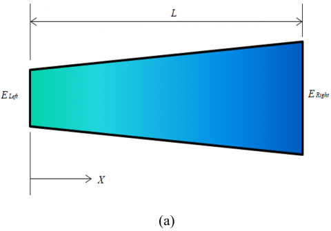
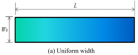
The uniform FG beam that has dimensions of (L*W*h) is illustrated in Figure 1. The elasticity modulus and other material attributes are changed along the length of the FG beam (i.e., axial direction) base on the power law model [47, 48]:
$E(x)=\left(E_{Left }-E_{Right }\right) *\left(1-\left(\frac{X}{L}\right)\right)^m+E_{Right }$ (1a)
$v(x)=\left(v_{Left }-v_{Right }\right) *\left(1-\left(\frac{X}{L}\right)\right)^m+v_{Right}$ (1b)
$\rho(x)=\left(\rho_{Left }-\rho_{Right}\right) *\left(1-\left(\frac{X}{L}\right)\right)^m+\rho_{Right}$ (1c)
where,
$E(x)$ is the elastic modulus as a function of $(x)$ through the axial direction.
$E_{\text {Left}}$ and $E_{\text {Right}}$ are the left and qright elastic moduli (Pa.).
$v(x)$ is the poison ratio as a function of $(x)$ through the axial direction.
$v_{\text {Left}}$ and $v_{\text {Right}}$ are the left and right poison ratio.
$\rho(x)$ is the density as a function of $(x)$ through the axial direction.
$\rho_{\text {Left}}$ and $\rho_{\text {Right}}$ are the left and right density $\left(\mathrm{Kg} / \mathrm{m}^3\right)$.
$L$ is the length of the FG beam.
$m$ is power law index.
Figure 1. Dimensions of the uniform FG beam
The stiffness (E(x)*I) varies along the axial direction in the uniform FG beam because of varying of the modulus of elasticity only. This case was analyzed by Wadi et al. [47] using Finite Element Methods and Rayleigh.
When the FG beam is non-uniform, the stiffness varies along the axial direction because of varying both second moment of area and modulus of elasticity. As said previously, the modulus of elasticity is varied in axial orientation according to power law model (see Eq. (1)). According to the definition of the area second moment, the second moment of area is varied according to three cases (a) variation of width only, (b) variation of thickness or depth only and (c) variation of both thickness and width [48]. In other side, the variety of thickness and/or width can be linear or non-linear form. In this work, the thickness and width of the FG beams are varied linearly according to the next equations:
$W(x)=W_0 *\left(1+\alpha_w\left(\frac{X}{L}\right)\right)$ (2)
$h(x)=h_0 *\left(1+\alpha_h\left(\frac{X}{L}\right)\right)$ (3)
where,
$W(x)$ and $h(x)$ are the width and thickness at any point $(X)$ respectively.
$W_0$ and $h_0$ are the width and thickness at the beam's left side $(X=0)$.
$\alpha_w$ and $\alpha_h$ are the variation rate in width and thickness respectively.
According to definition of second moment of area (I) and by applying Eqs. (2) and (3), the second moment of area (I) is:
$I(x)=\frac{W(x) *(h(x))^3}{12}$
$I(x)=\left\{\begin{array}{c}\frac{\left(W_0 *\left(1+\alpha_w\left(\frac{X}{L}\right)\right)\right) * h_0{ }^3}{12} \text { Width Variation only } \\ \frac{W_0 *\left(h_0 *\left(1+\alpha_h\left(\frac{X}{L}\right)\right)\right)^3}{12} \text { Thickness Variation only } \\ \frac{\left(W_0 *\left(1+\alpha_w\left(\frac{X}{L}\right)\right)\right) *\left(h_0 *\left(1+\alpha_h\left(\frac{X}{L}\right)\right)\right)^3}{12} \text { Width and Thickness Variation }\end{array}\right.$ (4)
Eq. (4) represents the variation of second moment of area for non-uniform beam with linear variation in width and/or thickness of beam.
By combination Eqs. (1) and (4), the variation of stiffness of non-uniform FG beam can be estimated.
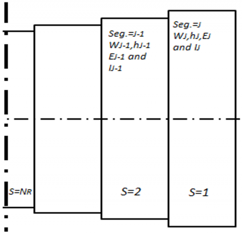
Generally, the analysis of non-uniform beam is difficult when the Rayleigh Method is used specially under the distribution load. In other hand, the axial-FGM leads to vary the properties of the material along the length of beam and causes non-uniformity in static deflection phenomena. In this work, Rayleigh Method is used to calculate the static transversal deflection of non-uniform axial-FG beams due to uniform distributed load. The non-uniformity in this case requires several steps in order to find the suitable way to represent the variation of modulus [47] and second moment of area [23] and these steps are:
$W($ Seg. $=i)=\frac{\left(W\left(X_i\right)+W\left(X_i+\Delta X\right)\right)}{2}$ (5)
$h($ Seg. $=i)=\frac{\left(h\left(X_i\right)+h\left(X_i+\Delta X\right)\right)}{2}$ (6)
$E(Seg.=i)=\frac{\left(E\left(X_i\right)+E\left(X_i+\Delta X\right)\right)}{2}$ (7)
According to Eqs. (5)-(7), the tapered axial-FG beam is transferred into beam with stepped dimensions and stepped modulus as displayed in Figure 3.
$(E I)_{e q}=\frac{(\mathrm{L})^3}{\sum_{n=1}^J \frac{(n * \Delta X)^3-((n-1) * \Delta X)^3}{(E I)_n}}$ (8)
The equivalent stiffness of simply supported stepped beams is computed by Eq. (9):
(NR) and (NL) are the steps number of right and left cantilever stepped beams respectively as displayed in Figure 5(c) and Figure 5(d). (LRight) and (LLeft) are the length of right and left cantilever stepped beams respectively. LLeft is the centroid of simply supported stepped beam and (LRight +LLeft=L).
Figure 2. Geometry and dividing of the non-uniform FG beam
Figure 3. Changing the non-uniform FG beam into stepped beam
Figure 4. Numbering of steps in clamped- free stepped beam
(a) Center of stepped beam
(b) Numbering of left and right parts
(c) Left free-clamped stepped beam
(d) Right free-clamped stepped beam
Figure 5. Numbering of steps of simply supported stepped beams
Table 1. Deflections of cantilever beams [47]
|
$\delta_{i j}=\delta_{j i}=\frac{W a^2(3 b-a)}{6 E I}$ |
|
$\delta_{i i}=\frac{W b^3}{3 E I}$ |
|
$\delta_{i k}=\delta_{k i}=\frac{W b^2(3 c-b)}{6 E I}$ |
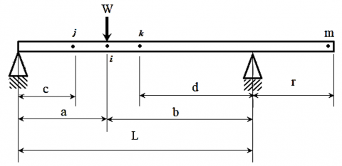
Table 2. Deflections formula of the deflections of simply supported beam at different points
|
$\delta_{i j}=\delta_{j i}=\frac{W b c\left(L^2-b^2-c^2\right)}{6 E I L}$ |
|
$\delta_{i i}=\frac{W a^2 b^2}{3 E I L}$ |
|
$\delta_{i k}=\delta_{k i}=\frac{W a d\left(L^2-a^2-d^2\right)}{6 E I L}$ |
|
$\delta_{i m}=\delta_{m i}=\frac{W a b r(L+a)}{6 E I L}$ |
$F(n)=\left\{\begin{array}{cc}P * \Delta X * W_0 & \text { when } n=2, \ldots J \\ \frac{P * \Delta X * W_0}{2} & \text { when } n=1 \text { and } J+1\end{array}\right.$ (10)
F(1)=0 and d(1)=0 (i.e., force and deflection at X=0 equals zero).
F(J+1)=0 and d(J+1)=0 (i.e., force and deflection at X=L equals zero)
F(1)=0 and d(1)=0 (i.e., force and deflection at X=0 equals zero).
F(J+1)=0 and d(J+1)=0 (i.e., force and deflection at X=L equals zero)
Finally, calculating the deflection (d) at each point by solving Eq. (11):
$[d]=[\delta][F]$ (11)
These steps are implemented using using Fortran power station in order to study the static deflection of linear tapered axial FG beam under distributed load with three types of supporting (clamped-free, free-clamped and simply supported).
Figure 6. The area of applied pressure in uniform and non-uniform width
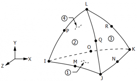
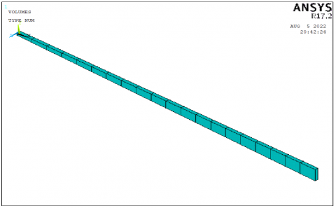
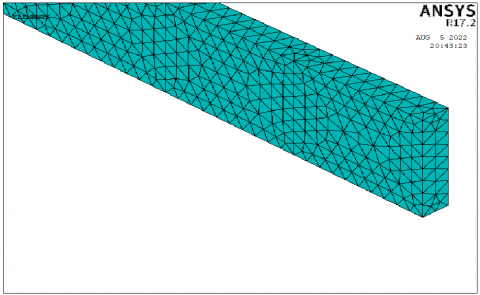
The Finite Element Method (FEM) was used to investigate the complex geometry and complex phenomena of any problem. Therefore, it is used to calculate the static deflection of axial-FG beam with tapered cross section area considering the non-uniformity in geometry, load and properties. Three-dimensional finite element model is constrained using ANSYS APDL 17.2 to simulate the tapered axial-FG beam under constant distributed load. In this model, beam is divided into twenty parts [47] as shown in Figure 7(b) and twenty sets of material properties are input into ANSYS software. The properties of each part are calculated using Eq. (1). The elastic modulus of each part is calculate using Eq. (7) (i.e., similar to Rayleigh Method). "SOLID187" is the 3-D element used in this work (see Figure 7). This element is a 10-nodes, higher order 3-D element. The element is defined by 10 nodes having 3 DOF at each node: translations in the x, y, and z directions. It has mixed formulation capability to simulate deformations of fully incompressible hyperelastic materials, and nearly incompressible elasto-plastic materials. Its quadratic displacement movements are good suitable for modeling irregular meshes (for those produced from various CAD/CAM systems). It also has large strain capabilities, large deflection, creep, stress stiffening, hyperelasticity, and plasticity [23, 45].
(a) Element SOLID187
(b) Tapered axial FG beam
(c) Meshing
Figure 7. The geometry and meshing of axial FG beam
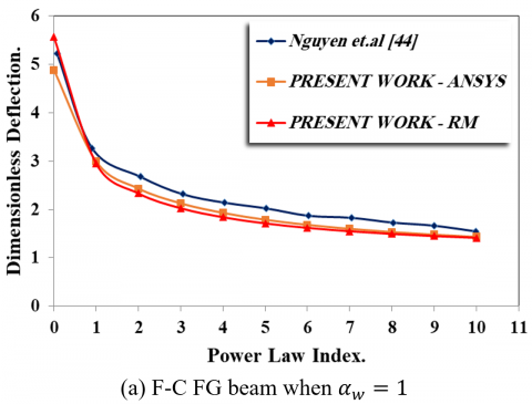
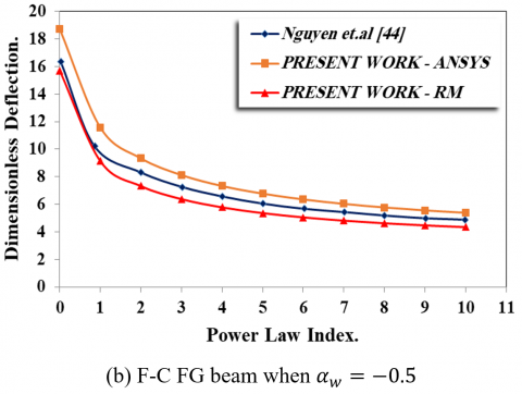
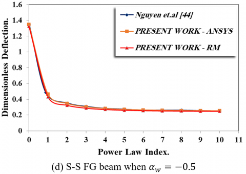
For checking of the present model accuracy of Rayleigh and ANSYS Methods, the static deflection results of Rayleigh Method are compared with that obtained by Nguyen et al. [44] for free-clamped and simply supported axial FG beam when the variation rate of the width $\left(\alpha_w\right)$ are (1) (i.e., $\left.W_0<W_1\right)$ and $(-0.5)\left(\right.$ i.e., $\left.W_0>W_1\right)$.
In this work, the used mechanical properties are: modulus of elasticity of left material is (390G Pa.); modulus of elasticity of right material is (210G Pa.); Poisson ratio of left material is (0.23) and Poisson ratio of right material is (0.3). The dimensionless static deflection can be determined by the following equation:
$\hat{\mathrm{d}}(x)=\mathrm{d}(x) \frac{384 * E_{left} * I_0}{5 q L^4}$ (12)
where,
$\widehat{\mathrm{d}}(x)$ is the dimensionless static deflection as a function of $(x)$ along the length of axial-FG beam and any value of $\boldsymbol{\alpha}_{\boldsymbol{w}}$ and $\alpha_h$.
$\mathrm{d}(x)$ is the static deflection at any point $(x)$ along the length of axial-FG beam and any value of $\boldsymbol{\alpha}_{\boldsymbol{w}}$ and $\boldsymbol{\alpha}_{\boldsymbol{h}}$.
$(q)$ is the distributed load $(\mathrm{N} / \mathrm{m})$.
( $I_0$ ) is the second moment of area at $\mathrm{X}=0$.
Figure 8 shows a comparison between the results of present (Rayleigh and ANSYS) models and that of Nguyen et al. [44] which were chosen for comparison because the investigated some similar cases of this study numerically. For simply supported axial FG beam, very good agreement is shown between the present models and Nguyen et al. [44] model when $\alpha_{\mathrm{w}}$ = 1 and $\alpha_{\mathrm{w}}$ = -0.5. In free- clamped axial FG beam, the comparison shows very good accordance between the present models and Nguyen et al. [44] model specially when $\alpha_{\mathrm{w}}$ = 1, and the results of present models is lower than that of Nguyen et al. [44]. When $\alpha_{\mathrm{w}}$ = -0.5, the results of Nguyen et al. [44] model are smaller than ANSYS results and larger than Rayleigh results. Generally, the minimum and maximum percentages of discrepancy between the present models and Nguyen et al. [44] model are listed in Table 3. There was an exceptional agreement between the results of present (Rayleigh and ANSYS) models and that of Nguyen et al. [44], and the maximum absolute percentages of discrepancy was 14% when α=-0.5 for clamped-free FGM beam.
Figure 8. The validation of the present models
Table 3. Maximum and minimum percentages of discrepancy for the present models compared to Nguyen et al. [44] model
|
Supporting Type and α Value |
Present Work-ANSYS |
Present Work-RM |
||
|
Discrepancy Percentages |
Discrepancy Percentages |
|||
|
Max. |
Min. |
Max. |
Min. |
|
|
α=1-FC |
12.4865 |
6.65044 |
2.1954 |
-5.6044 |
|
α=1-SS |
1.07696 |
-8.4902 |
2.7003 |
-6.505 |
|
α=-0.5-FC |
-10.2437 |
-14.5467 |
-9.5314 |
-13.4674 |
|
α=-0.5-SS |
3.9378 |
-1.64305 |
11.1878 |
0.978 |
In this work, the variation rates of non-prismatic axial FG beam are considered (i.e., αb, αh and α). The values of variation rate are (0, 0.25, 0.5, 0.75, 1, 1.25, 1.5, 1.75, 2, 2.25, 2.5, 2.75 and 3). Also, the effects of material distribution (i.e., power law index (m)) and type of supporting on the dimensionless static deflection under uniform distributed load are studied. The expected results show the relationship between the maximum dimensionless static deflection with the considered variable parameters of the study like material distribution parameter, variation rate (α), etc.
6.1 Variation rate of non-prismatic axial FG beam
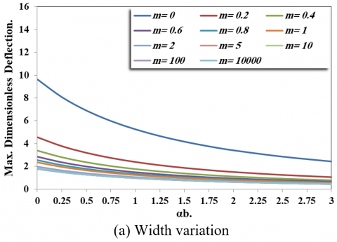
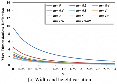
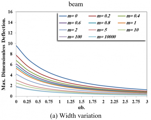
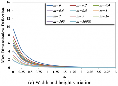
In this section, the effect of variation rates (i.e., αb, αh and α) on the maximum dimensionless static deflection of simply supported axial FG beam is discussed. The results found that the second moment of area is varied depending on the variation of beam dimensions. The second moment of area (I) for the width variation case is smaller than the second moment of area (I) for height variation and width and height variation cases. Therefore, the maximum dimensionless static deflection for width variation case is larger than that of other cases at any value of power law index (m).
Figure 9 shows the effect of variation rates (i.e., αb, αh and α) on the maximum dimensionless static deflection of simply supported axial FG beam. Generally, the dimensionless static deflection decreases when the variation rate (i.e., αb, αh and α) increases because of increasing the equivalent stiffness ((EI) eq). The maximum dimensionless static deflection of axial FG beam in width variation (i.e., αb) (as shown in Figure 9(a)) decreases with the rate smaller than that of height and both width and height variation (i.e., αh and α) (as shown in Figure 9(b) and Figure 9(c)). In order to explain the effect of beam dimensions variation of axial FG beam, the following points must be considered:
Figure 9. Effect of variation on the maximum dimensionless static deflection of clamped-free non-prismatic axial FG beam
Figure 10. Effect of variation on the maximum dimensionless static deflection of free-clamped non-prismatic axial FG beam
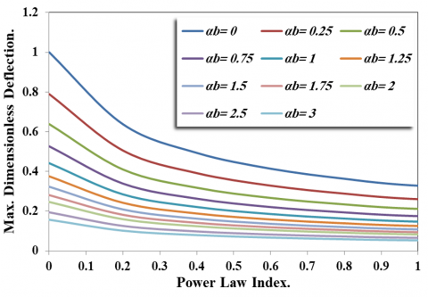
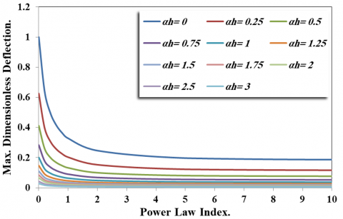
6.2 The effect of material distribution parameter (Power law index)
Generally, the modulus increases of prismatic and non-prismatic axial FG beam when the material distribution parameter increases, and this causes decreasing the maximum dimensionless static deflection. The maximum dimensionless static deflection tends to be constant when the material distribution parameter is greater than (5).
(a) Width variation
(b) Height variation
(c) Width and height variation
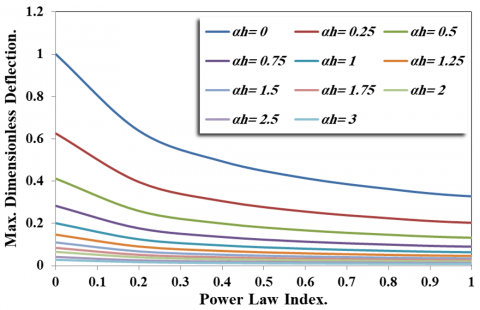
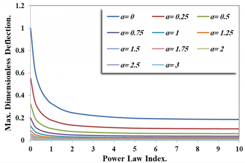
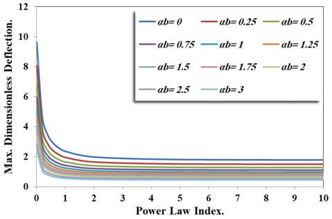
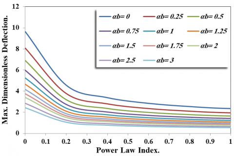
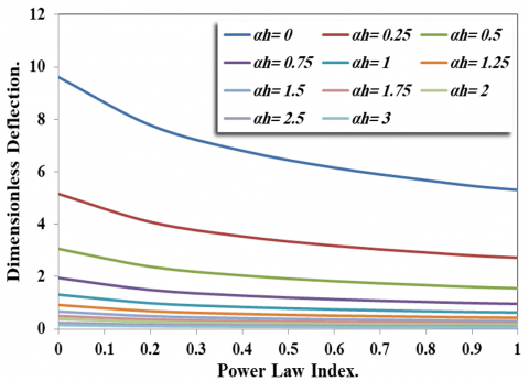
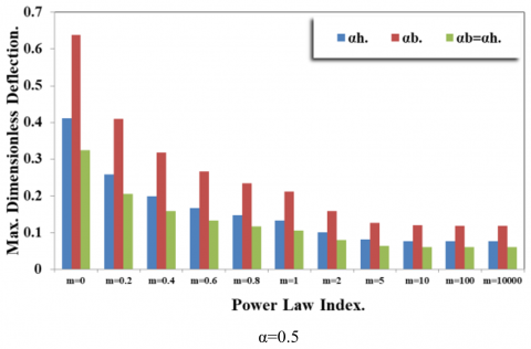
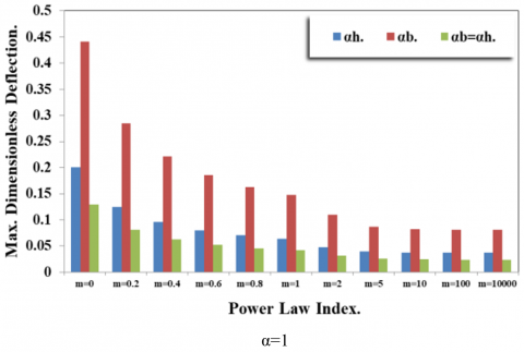
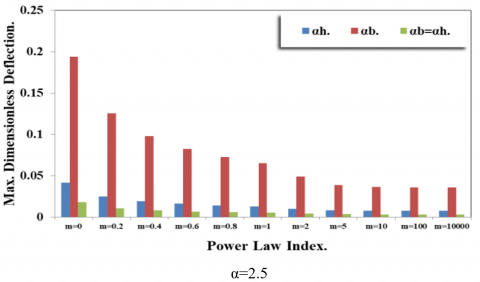
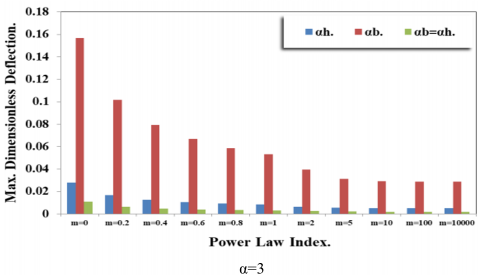
Figure 11. Effect of power law index on the dimensionless static deflection of simply supported non-prismatic axial FG beam
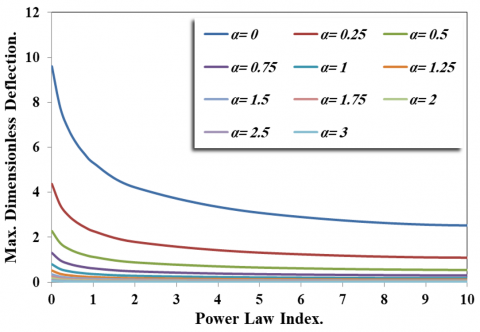
The effect of material distribution on the maximum dimensionless static deflection of simply supported non-prismatic axial FG beam with different variation rates under uniform distributed load is shown in Figure 11. Generally, the modulus of prismatic and non-prismatic axial FG beam increases when the material distribution parameter increases, and this causes decreasing the maximum dimensionless static deflection. In other side, the maximum dimensionless static deflection also decreases due to increase the cross-section area (width, height or both width and height) as illustrated previously. Figures 12 and 13 display the change of maximum dimensionless static deflection of clamped-free and free-clamped axial FG beam due to the change of the cross-section area. From these figures, it can be concluded that the maximum dimensionless static deflection tends to be constant when the material distribution parameter is greater than (5).
(a) Width variation
(b) Height variation
(c) Width and height variation
Figure 12. Effect of power law index on the dimensionless static deflection of clamped-free non-prismatic axial FG beam
(a) Width variation
(b) Height variation
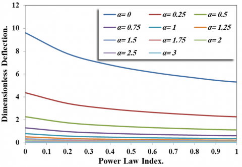
(c) Width and height variation
Figure 13. Effect of power law index on the dimensionless static deflection of free-clamped non-prismatic axial FG beam
6.3 The effect of supporting type
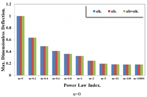
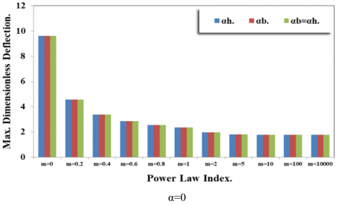
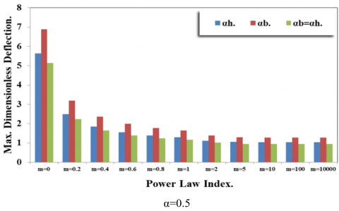
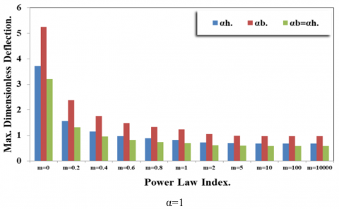
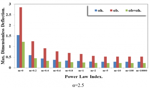
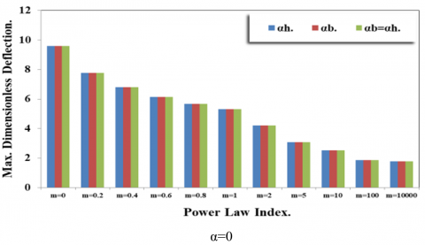
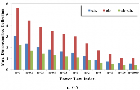
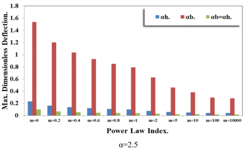
Figure 14 shows a comparison of the maximum dimensionless static deflections of simply supported axial FG beam with different variation rates (i.e., αb, αh and α) and different material distribution parameter (m). When α=0 (i.e., beam is uniform), the dimensionless maximum static deflection decreases when the material distribution parameter increases. When α=1 (i.e., linear variation), the dimensionless maximum static deflection also decreases when the material distribution parameter increases but the maximum dimensionless static deflection of width variation case is larger than that of height variation case and width and height variation case respectively. The decreasing rate of maximum dimensionless static deflection increases when the variation rate increases for any material distribution parameter.
Figure 14. Comparison between the dimensionless static deflection of simply supported non-prismatic axial FG beam with different power law index and three variation cases
From Figures 15 and 16, the maximum dimensionless static deflection of clamped-free prismatic axial FG beam is smaller than that of free-clamped prismatic axial FG beam (i.e., α=0). This difference occurs due to change of the supporting point. In clamped-free beam, the fixed point is at the left (stronger) side (i.e., stronger material), while the free point is at the right (weaker) side (i.e. weaker material). When the material distribution parameter and variation rate increase, the effect of supporting position is appeared sharply in unsymmetrical supported conditions.
Figure 15. Comparison between the dimensionless static deflection of clamped-free non-prismatic axial FG beam with different power law index and three variation cases
Figure 16. Comparison between the dimensionless static deflection of free - clamped non-prismatic axial FG beam with different power law index and three variation cases
In this work, Rayleigh method was used to analyze the static deflection of non-prismatic axial FG beam under uniform distributed load. The linear change of width or height or both width and height were assumed to describe behavior of the non-prismatic beam and the power law model was used to define the material distribution along the axial direction. The following points can be concluded from the results:
This work introduced a good understanding for the effects of FG beam dimensions variation on the static deflection and this is useful for designing the suitable dimensions of FG beam according the requirements of beam application. As a future work, the non-linear FGM beam will be considered to study the ability of Rayleigh method to simulate the non-linearity in geometry, load and properties in the same time. This will be very significant for the industry and will open up numerous research avenues. Also, the 2-D FGM beam will be analyzed using Rayleigh method which is significantly affects the field of FGM.
[1] Kassner, M.E., Smith, K.K., Campbell, C.S. (2015). Low-temperature creep in pure metals and alloys. Journal of Materials Science, 50: 6539-6551. https://doi.org/10.1007/s10853-015-9219-2
[2] Xu, Q., Ma, A., Li, Y., Saleh, B., Yuan, Y., Jiang, J., Ni, C. (2019). Enhancement of mechanical properties and rolling formability in AZ91 alloy by RD-ECAP processing. Materials, 12(21): 3503. https://doi.org/10.3390/ma12213503
[3] Saleh, B., Jiang, J., Xu, Q., Fathi, R., Ma, A., Li, Y., Wang, L. (2021). Statistical analysis of dry sliding wear process parameters for AZ91 alloy processed by RD-ECAP using response surface methodology. Metals and Materials International, 27: 2879-2897. https://doi.org/10.1007/s12540-020-00624-w
[4] Xu, Q., Ma, A., Saleh, B., Li, Y., Yuan, Y., Jiang, J., Ni, C. (2020). Enhancement of strength and ductility of SiCp/AZ91 composites by RD-ECAP processing. Materials Science and Engineering: A, 771: 138579. https://doi.org/10.1016/j.msea.2019.138579
[5] Zainy, H.Z., Al-Ansari, L.S., Al-Hajjar, A.M., Mahdi, M., Shareef, S. (2018). Analytical and numerical approaches for calculating the static deflection of functionally graded beam under mechanical load. International Journal of Engineering & Technology, 7(4): 3889-3896. https://doi.org/10.14419/ijet.v7i4.20515
[6] Saleh, B., Jiang, J., Fathi, R., Al-Hababi, T., Xu, Q., Wang, L., Song, D., Ma, A. (2020). 30 Years of functionally graded materials: An overview of manufacturing methods, Applications and Future Challenges. Composites Part B: Engineering, 201: 108376. https://doi.org/10.1016/j.compositesb.2020.108376
[7] Ghani, S.N., Neamah, R.A., Abdalzahra, A.T., Al-Ansari, L.S., Abdulsamad, H.J. (2022). Analytical and numerical investigation of free vibration for stepped beam with different materials. Open Engineering, 12(1): 184-196. https://doi.org/10.1515/eng-2022-0031
[8] Yavari, A., Sarkani, S., Moyer Jr, E.T. (2000). On applications of generalized functions to beam bending problems. International Journal of Solids and Structures, 37(40): 5675-5705. https://doi.org/10.1016/S0020-7683(99)00271-1
[9] Yavari, A., Sarkani, S., Reddy, J.N. (2001). Generalized solutions of beams with jump discontinuities on elastic foundations. Archive of Applied Mechanics, 71: 625-639. https://doi.org/10.1007/s004190100169
[10] Biondi, B., Caddemi, S. (2005). Closed form solutions of Euler–Bernoulli beams with singularities. International Journal of Solids and Structures, 42(9-10): 3027-3044. https://doi.org/10.1016/j.ijsolstr.2004.09.048
[11] Biondi, B., Caddemi, S. (2007). Euler-Bernoulli beams with multiple singularities in the flexural stiffness. European Journal of Mechanics-A/Solids, 26(5): 789-809. https://doi.org/10.1016/j.euromechsol.2006.12.005
[12] Naguleswaran, S. (2002). Natural frequencies, sensitivity and mode shape details of an Euler-Bernoulli beam with one-step change in cross-section and with ends on classical supports. Journal of Sound Vibration, 252(4): 751-767. https://doi.org/10.1006/jsvi.2001.3743
[13] Naguleswaran, S. (2002). Vibration of an Euler-Bernoulli beam on elastic end supports and with up to three step changes in cross-section. International Journal of Mechanical Sciences, 44(12): 2541-2555. https://doi.org/10.1016/S0020-7403(02)00190-X
[14] Koplow, M.A., Bhattacharyya, A., Mann, B.P. (2006). Closed form solutions for the dynamic response of Euler-Bernoulli beams with step changes in cross section. Journal of Sound and Vibration, 295(1-2): 214-225. https://doi.org/10.1016/j.jsv.2006.01.008
[15] Stanton, S.C., Mann, B.P. (2010). On the dynamic response of beams with multiple geometric or material discontinuities. Mechanical Systems and Signal Processing, 24(5): 1409-1419. https://doi.org/10.1016/j.ymssp.2009.11.009
[16] Lu, Z.R., Huang, M., Liu, J.K., Chen, W.H., Liao, W.Y. (2009). Vibration analysis of multiple-stepped beams with the composite element model. Journal of Sound and Vibration, 322(4-5): 1070-1080. https://doi.org/10.1016/j.jsv.2008.11.041
[17] Popplewell, N., Chang, D. (1996). Free vibrations of a complex Euler-Bernoulli beam. Journal of Sound and Vibration, 190(5): 852-856. https://doi.org/10.1006/jsvi.1996.0098
[18] Cekus, D. (2012). Free vibration of a cantilever tapered Timoshenko beam. Scientific Research of the Institute of Mathematics and Computer Science, 11(4): 11-17.
[19] Wattanasakulpong, N., Charoensuk, J. (2015). Vibration characteristics of stepped beams made of FGM using differential transformation method. Meccanica, 50: 1089-1101. https://doi.org/10.1007/s11012-014-0054-3
[20] Wang, X., Wang, Y. (2013). Free vibration analysis of multiple-stepped beams by the differential quadrature element method. Applied Mathematics and Computation, 219(11): 5802-5810. https://doi.org/10.1016/j.amc.2012.12.037
[21] Al-Ansari, L.S. (2012). Calculating of natural frequency of stepping cantilever beam. International Journal of Mechanical & Mechatronics Engineering IJMME-IJENS, 12(5): 59-68.
[22] Al-Ansari, L.S. (2013). Calculating static deflection and natural frequency of stepped cantilever beam using modified Rayleigh method. International Journal of Mechanical and Production Engineering Research and Development. (IJMPERD), 3(4): 107-118.
[23] Alansari, L.S., Zainy, H.Z., Yaseen, A.A., Aljanabi, M. (2019). Calculating the natural frequency of hollow stepped cantilever beam. International Journal of Mechanical Engineering and Technology (IJMET), 10(1): 898-914. https://doi.org/10.14419/ijet. v7i4.25334
[24] Alansari, L.S., Zainy, H.Z., Yaseen, A.A., Aljanabi, M. (2019). Calculating the natural frequency of hollow stepped cantilever beam. International Journal of Mechanical Engineering and Technology (IJMET), 10(1): 898-914.
[25] Diwan, A.A., Al-Ansari, L.S., Al-Saffar, A.A., Al-Anssari, Q.S. (2022). Experimental and theoretical investigation of static deflection and natural frequency of stepped cantilever beam. Australian Journal of Mechanical Engineering, 20(2): 303-315. https://doi.org/10.1080/14484846.2019.1704494
[26] Al-Saffar, A.A., Diwan, A.A., Al-Ansari, L.S., Alkhatat, A. (2020). Experimental and artificial neural network modeling of natural frequency of stepped cantilever shaft. Journal of Mechanical Engineering Research Development, 43(4): 299-309.
[27] Abdulsamad, H.J., Wadi, K.J., Al-Raheem, S.K., Alansari, L.S. (2021). Investigation of static deflection in internal stepped cantilever beam. Journal of Mechanical Engineering Research and Developments, 44(5): 87-125.
[28] Mazanoglu, K. (2017). Natural frequency analyses of segmented Timoshenko-Euler beams using the Rayleigh-Ritz method. Journal of Vibration and Control, 23(13): 2135-2154. https://doi.org/10.1177/1077546315611525
[29] Zhu, H., Sankar, B.V. (2004). A combined Fourier series-Galerkin method for the analysis of functionally graded beams. Journal of Applied Mechanics, 71(3): 421-424. https://doi.org/10.1115/1.1751184
[30] Chakraborty, A., Gopalakrishnan, S., Reddy, J. (2003). A new beam finite element for the analysis of functionally graded materials. International Journal of Mechanical Sciences, 45(3): 519-539. https://doi.org/10.1016/S0020-7403(03)00058-4
[31] Zhong, Z., Yu, T. (2007). Analytical solution of a cantilever functionally graded beam. Composites Science and Technology, 67(3-4): 481-488. https://doi.org/10.1016/j.compscitech.2006.08.023
[32] Nie, G.J., Zhong, Z., Chen, S. (2013). Analytical solution for a functionally graded beam with arbitrary graded material properties. Composites Part B: Engineering, 44(1): 274-282. https://doi.org/10.1016/j.compositesb.2012.05.029
[33] Li, X.F. (2008). A unified approach for analyzing static and dynamic behaviors of functionally graded Timoshenko and Euler-Bernoulli beams. Journal of Sound and Vibration, 318(4-5): 1210-1229. https://doi.org/10.1016/j.jsv.2008.04.056
[34] Şimşek, M., Kocatürk, T., Akbaş, Ş.D. (2013). Static bending of a functionally graded microscale Timoshenko beam based on the modified couple stress theory. Composite Structures, 95: 740-747. https://doi.org/10.1016/j.compstruct.2012.08.036
[35] Helal, S.H.B. (2020). The static analysis of a functionally graded Euler beam under mechanical loads. Doctoral dissertation, Master thesis, University of Kufa.
[36] Helal, S.B., Al-Ansari, L.S., Mohammed, H.H. (2019). Static analysis of a functionally graded beam under thermal and mechanical load. International Journal of Machine Design and Manufacturing, 5(2): 39-51.
[37] Abbood, Z., AlAnsari, L.S. (2021). Free vibration analysis of simply supported power law functionally graded beam using Finite Element Method. Al-Furat Journal of Innovation in Mechanical and Sustainable Energy Engineering, 1(1): 24-45. https://journals.atu.edu.iq/index.php/fjimse/article/view/74.
[38] Neamah, R.A., Nassar, A.A., Alansari, L.S. (2022). Review on buckling and bending analysis of functionally graded beam with and without crack. Basrah Journal for Engineering Sciences, 22(1): 69-77. http:/doi.org/10.33971/bjes.22.1.8
[39] Shahba, A., Attarnejad, R., Marvi, M.T., Hajilar, S. (2011). Free vibration and stability analysis of axially functionally graded tapered Timoshenko beams with classical and non-classical boundary conditions. Composites Part B: Engineering, 42(4): 801-808. https://doi.org/10.1016/j.compositesb.2011.01.017
[40] Mahmoud, M.A. (2019). Natural frequency of axially functionally graded, tapered cantilever beams with tip masses. Engineering Structures, 187: 34-42. https://doi.org/10.1016/j.engstruct.2019.02.043
[41] Lin, X., Huang, Y., Zhao, Y., Wang, T. (2019). Large deformation analysis of a cantilever beam made of axially functionally graded material by homotopy analysis method. Applied Mathematics and Mechanics, 40: 1375-1386. https://doi.org/10.1007/s10483-019-2515-9
[42] Soltani, M., Asgarian, B. (2019). Finite element formulation for linear stability analysis of axially functionally graded nonprismatic Timoshenko beam. International Journal of Structural Stability and Dynamics, 19(02): 1950002. https://doi.org/10.1142/S0219455419500020
[43] Daikh, A.A., Houari, M.S.A., Belarbi, M.O., Chakraverty, S., Eltaher, M.A. (2022). Analysis of axially temperature-dependent functionally graded carbon nanotube reinforced composite plates. Engineering with Computers, 38(Suppl 3): 2533-2554. https://doi.org/10.1007/s00366-021-01413-8
[44] Nguyen, N.T., Kim, N.I., Cho, I., Phung, Q.T., Lee, J. (2014). Static analysis of transversely or axially functionally graded tapered beams. Materials Research Innovations, 18(sup2): S2-260. https://doi.org/10.1179/1432891714Z.000000000419
[45] Nguyen, D.K. (2013). Large displacement response of tapered cantilever beams made of axially functionally graded material. Composites Part B: Engineering, 55: 298-305. https://doi.org/10.1016/j.compositesb.2013.06.024
[46] Rajasekaran, S., Bakhshi Khaniki, H. (2019). Finite element static and dynamic analysis of axially functionally graded nonuniform small-scale beams based on nonlocal strain gradient theory. Mechanics of Advanced Materials and Structures, 26(14): 1245-1259. https://doi.org/10.1080/15376494.2018.1432797
[47] Wadi, K.J., Yadeem, J.M., Al-Ansari, L.S., Abdulsamad, H.J. (2022). Static deflection calculation for axially FG cantilever beam under uniformly distributed and transverse tip loads. Results in Engineering, 14: 100395. https://doi.org/10.1016/j.rineng.2022.100395
[48] Hashim, W.M., Alansari, L.S., Aljanabi, M., Raheem, H.M. (2022). Investigating static deflection of non-prismatic axially functionally graded beam. Material Design & Processing Communications, 2022: 12. https://doi.org/10.1155/2022/7436024