Chabane Medjdoub*![]() | Abdelhakim Benslimane
| Abdelhakim Benslimane![]() | Djamel Sadaoui
| Djamel Sadaoui![]() | Karim Bekkour
| Karim Bekkour![]()
© 2024 The authors. This article is published by IIETA and is licensed under the CC BY 4.0 license (http://creativecommons.org/licenses/by/4.0/).
OPEN ACCESS
In the present article, a novel coaxial with shell-and-tube (CWST) heat exchanger is developed and simulated using Ansys-Fluent®, and its results are compared with those of the shell-and-tube heat exchanger from which it is derived. The geometry of this new exchanger was given, specifying the different types of fluids it can contain and their circulations, and a theoretical calculation based on the NTU method (number of transfer units method) is used to validate the simulations. In order to be able to analyse the phenomena occurring inside this exchanger, the fluid temperature, pressure, and velocity distribution figures are given with the evolutionary curve of some performance parameters (the heat, the pressure losses, the ratio between heat and pressure losses, the heat flux and the overall heat transfer coefficient) as a function of the cold fluid volume rate. At the end the various advantages it can give to enhance the efficiency of heat transfer, to reduce manufacturing and operating costs, as well as its potential for further research on the improvement of the design were explained.
shell-and-tube, simulation, performances, new coaxial with shell-and-tube heat exchanger
While various types of heat exchangers exist, including tube coil and plate heat exchangers, the shell-and-tube heat exchanger (STHE) stands out as the most widely utilized in the industry due to its superior exchange surfaces, efficient heat transfer capabilities, and compact design. These heat exchangers are used for industries that require heat transfer in order to support the chemical processes such as distillation, synthesis or combustion, which takes place in the pharmaceutical, food and petrochemical industries. They can also be used for the conversion of fossil or atomic energy into electricity as in nuclear power plants, and they are employed for heat pumps, heating and air conditioning which use heat transfer to change or maintain the temperature in enclosed spaces such as cold rooms.
The lack of energy resources, climate change due to pollution and the desire for economic prosperity of countries makes research into improving the performance of heat exchangers more than necessary. There is an important number of works in the literature dealing with heat exchangers, both from a numerical and experimental point of view, and whose main objective remains the optimization and improvement of heat transfer in these devices. Below, we discuss some studies and methods for enhancing heat exchanger performance:
Characteristics of the tubes used in heat transfer are essential for the performance of the heat exchangers; some research has focused on their shapes which can be twisted, coiled or finned. Tan et al. [1] investigated, through CFD simulation, heat exchangers utilizing finned tubes and twisted oval tubes, both of which offer enhanced turbulence compared to smooth circular tubes. The authors observed that the exchangers that use finned tubes increase the transfer area which increases the rate of the exchanged heat. In the twisted oval tube heat exchanger, it was discovered that the torsion pitch's length had a greater impact on heat transfer performance. In an experimental research employing turbulent water flow on a heat exchanger using twisted tubes, Zhang et al. [2] found that reducing the torsion pitch increases both the heat transfer and friction coefficient. In an experimental investigation, Dizaji et al. [3] found that inserting air bubbles into a vertical heat exchanger with coil tubes increases the exchanger's efficiency and NTU. Genic et al. [4] studied experimentally spiral tube (coil) heat exchanger and concluded that the heat transfer is improved by increasing the diameter and the pitch length of the coil as well as increasing the flow rate.
In other hand, some other studies have focused on baffles and their different features. Zhang et al. [5] carried out an experimental study to compare between shell-and-tube heat exchanger using segmented baffles with shell-and-tube heat exchanger using overlapped helical baffles. And they were able to determine that the second kind of heat exchanger exhibits better heat transfer per unit pressure drop and had less pressure drop across the shell than the first type. In their studies of shell-and-tube heat exchangers with helical baffles, Zhang et al. [6, 7] used simulation and experimentation, respectively. Both groups came to the conclusion that this kind of heat exchanger with helical baffles has a greater effect on increasing turbulence by disrupting the fluid flow on the shell, which in turn allows for an increase in heat transfer. Additionally, they noticed that the pressure drop significantly decreases which decreases the pressure drop rate per unit length of the heat exchanger. A shell-and-tube heat exchanger with helical baffles was simulated by Xiao et al. [8] for various Prandtl number values and inclination angles. They concluded that water provided better heat transfer at 40° baffle angle, and the fluids with high Prandtl numbers recorded better heat transfer at small angles of inclination. Additionally, they mentioned that pressure drops are reduced with helical baffle exchangers than with ones with segmented baffles. An experimental study of the shell-and-tube heat exchanger with one pass on the shell and two passes on the tubes was conducted by Vukič et al. [9]. They came to the conclusion that the exchanger's performances are more dependent on geometrical parameters located on the shell, such as the number and size of baffles, which increase the heat transfer and pressure drops. A STHE model with a 25% baffle cut and three types of tubes was created by Safarian et al. [10] using COMSOL®. The simulation was validated in terms of the pressure drop as a function of the mass flow on the shell side, and a typical k-ε model with a standard wall function was employed combined with a coarse mesh. Using a tube bundle of 19 tubes operating in a single pass and various inventive baffle designs, Li et al. [11] carried out an experimental and computational study of a STHE with a mesh grid of 2.32 million cells and a realizable k-ε model. Another investigation was carried out numerically by El-Said et al. [12], who used a standard k-ε to represent a shell-and-tube exchanger with curved segmental baffles. Using the SST k-ω turbulence model, Slimene et al. [13] conducted a numerical simulation to study the turbulent flows in a shell-and-tube heat exchanger with different passes. Next, this model was expanded to include a rectangular shell design and baffles that improve heat exchanger performance. A succinct summary of the passive heat transfer enhancement approaches (such as the use of baffles) and the most significant types of heat exchanger was provided by Ali et al. [14].
Other studies on rod baffles and other types of baffles have been conducted; In a comparative numerical simulation research, Yang and Liu [15] compared two shell-and-tube heat exchangers with rod baffles and plate baffles. They found that the exchanger with plate baffles had a greater Nusselt number than the one with rod baffles. Chen et al. [16] conducted a comparative analysis of three distinct types of shell-and-tube heat exchanger baffles: rod, three-flower, and pore plate baffles. The authors found that all three types of baffles outperformed the segmented baffle heat exchanger. After conducting an experimental investigation, Wang et al. [17] found that a shell-and-tube heat exchanger with two shell passes and rod baffles outperformed a single shell pass exchanger with the same kind of baffles. In a comparative simulation study, Liu et al. [18] compared the thermo-hydraulic performance of two shell-and-tube heat exchangers with rod baffles: one with spirally corrugated tubes and the other with plain tubes. Their findings indicate that the exchanger equipped with corrugated tubes demonstrated superior thermo-hydraulic performance.
Interesting and original studies have been carried out and some have resulted in new designs and structures; By simulating a shell-and-tube heat exchanger using elastic tubes, Ji et al. [19] found that, for flows with low Reynolds numbers, adding vibrations on the shell side can improve heat transfer. Bougriou and Baadache [20] have created a new heat exchanger called the shell-and-double concentric-tube heat exchanger, which increases the exchange surface and the heat transfer in a smaller volume. The performance of a new four-pass micro scooter radiator, measuring 90 cm in length and using ambient air to cool hot water, was experimentally investigated by Trang et al. [21]. They found that according to some water flow rates, the water cooling was enhanced by using a fan, and became superior to the cooling of larger conventional radiators. They also found that the engine power increased with less fuel consumption, and thus the cost of the mini radiator decreased compared to larger conventional radiators.
Plate heat exchangers and especially nanofluids have been the subject of very important research. Lozano et al. [22] conducted an experimental and numerical study related to automotive industry, on a grooved plate heat exchanger that circulating water and oil, and they came to the conclusion that the two fluids' flows are irregular and tend to flow along the lateral edges of the plates. Using a CuO/water nanofluid, Khairul et al. [23] studied a corrugated plate heat exchanger and found that it results in lower exergy losses than water. The impact of nanofluids on shell-and-tube heat exchanger performance was investigated by Elias et al. [24], Leong et al. [25], and Elias et al. [26]. The first group studied baffles from various angles and came to the conclusion that using nanofluids consistently produced good results. In their comparison, the second group found that using nanofluids outperforms using ethylene glycol and water in terms of convection coefficient and overall heat transfer coefficient. The third group came to the conclusion that factors influencing the heat exchanger's performance include the size, shape, and volume concentration of the particles that constitute the nanofluids. Through experimental investigation, Philip et al. [27] found that when magnetic nanoparticles are subjected to an external magnetic field, their thermal conductivity increases. Yu et al. [28] studied the effect of grapheme nanosheets that have very interesting properties such as corrosion and erosion resistance, and concluded that mixing them with an ethylene glycol base result in an improvement of its thermal conductivity. The impact of Al2O3 nanofluids on a compact plate heat exchanger was experimentally investigated by Ajeeb et al. [29], who emphasized the significance of its application in enhancing heat transfer performance. Through the use of multiple flow rates, Dasore et al. [30] conducted a numerical analysis of a counter-flow spiral plate heat exchanger and were able to derive a Nusselt correlation that applied to this particular device.
Another approach to heat exchanger research is the use of optimisation techniques based on different calculation algorithms. Touatit and Bougriou [31] used a techno-economic approach through a Fortran-based calculation code to determine the temperature profiles, heat transfer coefficients, and total friction power, in order to conduct an optimization study on a triple concentric tube exchanger that circulates hydrogen, nitrogen, and oxygen. Ultimately, they were able to determine the ideal diameters to reduce manufacturing expenses and energy consumption. The performance of the shell-and-tube heat exchangers was optimized by Xie et al. [32], Fettaka et al. [33], and Guo et al. [34] using non-deterministic prediction systems, including the genetic algorithm for the third group, the multi-objective optimization method for the second, and the artificial neural method for the first. Through an optimization study, Şahin et al. [35] used the artificial bee colony approach on a shell-and-tube heat exchanger, and by comparing their findings with previous research, they came to the conclusion that this method can reduce the heat exchanger's manufacturing and operating costs. By optimizing the objective function that characterizes the synergy field number, Guo et al. [36] conducted an optimization study of a shell-and-tube heat exchanger. This number demonstrates the synergy between the heat flow and the velocity field, which led to the conclusion that using it results in better design costs and performance than minimizing the objective function which represents the overall cost. In order to reduce the overall cost of the heat exchanger, Fesanghary et al. [37] investigated the optimization of a shell-and-tube heat exchanger using the harmonic search algorithm and global sensitivity analysis. And they found that this approach produced more accurate optimization than the genetic algorithm method. Using data from a convex plate exchanger obtained by the two-layer multi-objective optimization technique, Wang et al. [38] conducted an experimental and numerical study to show how this method can be utilized to improve the device's thermal performance.
Some of the articles mentioned above have proceeded to create new exchanger structures that have great potential for improving their performances. In our paper, we proceeded in the same way, by creating a new structure based on the STHE and the coaxial exchanger, and numerical simulations were undertaken on the newly designed heat exchanger to investigate velocity, temperature and pressure fields. The obtained results were compared to the results of a classical STHE, then we were able to deduce its advantages and analyse the phenomena that produce them. We showed that the novel CWST exchanger allows, through its geometry, to produce more turbulence due to the increase of his singularities, which makes possible to increase the exchanged heat compared to the STHE. It also produces less pressure losses due to the different distribution of the flow rate between tubes which is caused by the coaxial channel and which reduces the mean velocity in it. In addition, it makes possible to reduce the volume of the tubes which allows the reduction of its manufacturing cost.
As demonstrated in the introduction, creating a new geometry can improve heat transfer performance, so we adopt a new geometry called CWST exchanger which will be explained with more detail in this section (see Table 1 for comparison with the STHE).
In order to compare the CWST heat exchanger to the STHE, we have to define their geometries, then carry out three simulations: the first on the CWST exchanger with its distributors, the second on the STHE with its distributors, and the third on the STHE with the same geometry as the second simulation but without distributors. This latter will enable us to verify the results of the simulations by comparing its results with those of a theoretical calculation that neglects the heat transfer via the tube sheets and other potential distributor effects. Then, the STHE with distributors will be compared to the CWST exchanger.
Figures 1-3 illustrate the geometry of the STHE which is studied in the present work. The two STHE (with and without distributors) shall have a maximum number of tubes arranged in a triangular pattern with an angle of 30° between each tube and a horizontal line, while leaving a length between the centres of each tube called the pitch (Pt) and whose ratio Pt/do=1.5. This triangular arrangement allows good exchanged heat, and the well-defined length of the pitch reduces pressure losses while leaving space for the tubes to remain undamaged by any vibrations that may be caused.
The maximum number of copper tubes was found by using drawing software for the conception of the geometry, by placing each tube from the centre of the shell and respecting the triangular arrangement and the imposed pitch. The development of the structure stops near the shell where no more tubes can be placed.
The information concerning this STHE is shown in the Table 2.
Table 1. Comparison between the CWST exchanger and the STHE with distributors
|
CWST Exchanger |
STHE with Distributors |
|
A total of 25 copper tubes measuring 1 mm in thickness and 12 mm in outer diameter |
A total of 37 copper tubes measuring 1 mm in thickness and 12 mm in outer diameter |
|
4 distributors |
2 distributors |
|
A copper channel measuring 60 mm in internal diameter and 62 mm in external diameter, and 7 tubes placed inside |
No channel |
|
Two distributors are crossed by tubes |
No tubes inside distributors |
|
6 nozzles measuring 20 mm in inner diameter |
4 nozzles measuring 20 mm in inner diameter |
|
A shell with 600 mm of length and 130 mm of inside diameter |
A shell with 600 mm of length and 130 mm of inside diameter |
|
The distributors with 28 mm of void length |
The distributors with 28 mm of void length |
|
4 nozzles placed in the middle of the distributors |
2 nozzles placed in the middle of the distributors |
|
2 nozzles placed in a distance of 280 mm from the centre of the shell |
2 nozzles placed in a distance of 280 mm from the centre of the shell |
|
4 tubes sheets with a thickness of 2 mm and 0.071 W/(m.K) of thermal conductivity |
2 tubes sheets with a thickness of 2 mm and 0.071 W/(m.K) of thermal conductivity |
|
Insulated from the outside |
Insulated from the outside |
Table 2. The STHE's geometric dimensions
|
The shell's length «L» (m) |
0.6 |
|
The shell's inner diameter «Ds» (m) |
0.13 |
|
Outside tube diameter «do» (m) |
0.012 |
|
Number of tubes «Nt» |
37 |
|
Pitch «Pt» (m) |
0.018 |
|
PR=Pt/do |
1.5 |
|
Inside diameter of a tube «di» (m) |
0.01 |
|
Tube thickness «e» (m) |
0.001 |
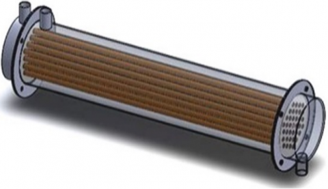
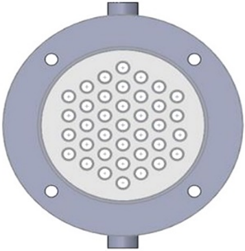
Figure 1. Geometry of the shell-and-tube heat exchanger
Figure 2. Representation of the tube bundle inside the STHE
Figure 3. Representation of the tube arrangement inside the STHE
Figures 4-6 illustrate the geometry of the novel configuration of the heat exchanger design. The CWST exchanger comes from the geometry of STHE mentioned above where we have to remove 12 small tubes of an external diameter of 12 mm and a thermal conductivity of 387.6 W/(m.K), in order to insert a large copper channel with an internal diameter of 60 mm and an external diameter of 62 mm. This heat exchanger has 18 small tubes located outside the large channel and connected with the latter to the first two distributors, and 7 small tubes located inside the large channel and connected to the last two distributors.
These heat exchangers are equipped with nozzles in the center of the distributors with an inner diameter of 20 mm, and they have two other shell nozzles which are placed from the centre of this shell by a distance of 280 mm. The tube sheets fixed to the distributors and the shell have a thermal conductivity of 0.071 W/(m.K) and have a thickness of 2 mm.
The distributors that allow the circulation of fluids in the shell have 28 mm of void length and are the continuity of the shell which has to be insulated from the outside.
Figure 4. Representation of the CWST heat exchanger
Figure 5. Representation of the tube arrangement in CWST exchanger
Figure 6. Representation of the geometry inside the CWST heat exchanger
In this section we execute a theoretical calculation using the NTU method in order to validate our simulations which use the same approach and similar geometries.
The two STHE operate in counter-current for better thermo-hydraulic performance. We use a hot water flow inside the tubes (25 l/min with Re=2477) and a cold water flow in the shell (2 l/min with Re=76) to minimize thermal losses outside the exchanger. The different flow rates and fluid properties which are used are shown in Table 3.
Table 3. The fluids' properties
|
Properties |
Hot Fluid |
Cold Fluid |
|
Cp [J/K.kg] |
4180 |
4170 |
|
ρ [kg/m3] |
989 |
997 |
|
λ [W/m.K] |
0.64 |
0.61 |
|
μ [Pa.s] |
0.000577 |
0.000855 |
|
qm [kg/s] |
0.41541 |
0.03323 |
|
Te [K] |
328 |
292 |
The theoretical calculations related to the STHE without distributors is used to find the overall heat transfer coefficient and the outlet temperatures of the exchanger. So, in order to achieve it, we start by finding the Reynolds number Re for each fluid, their Prandtl Pr and Nusselt Nu numbers (inside the tubes we use the Gnielinski correlation [39] for the Nusselt and the Blasius correlation [40] for the needed Cf).
The equations which are used are as follows:
For the fluid inside the tubes:
${{\operatorname{Re}}_{i}}=\frac{{{G}_{i}}\cdot di}{{{\mu }_{i}}}$ (1)
$C{{f}_{i}}=0.079\cdot \text{R}{{\text{e}}_{i}}^{-0.25}$ (2)
${{\Pr }_{i}}=\frac{{{\mu }_{i}}\cdot C{{p}_{c}}}{{{\lambda }_{i}}}$ (3)
$N{{u}_{i}}=\frac{(\frac{C{{f}_{i}}}{2})\cdot ({{\operatorname{Re}}_{i}}-1000){{\Pr }_{i}}}{1+12.7\cdot {{(\frac{C{{f}_{i}}}{2})}^{\frac{1}{2}}}\cdot ({{\Pr }_{i}}^{\frac{2}{3}}-1)}$ (4)
G is the surface flow rate which is calculated as follows:
${{S}_{i}}=\pi \cdot \frac{d{{i}^{2}}}{4}$ (5)
${{G}_{i}}=\frac{q{{m}_{i}}}{Nt\cdot {{S}_{i}}}$ (6)
For the fluid outside the tubes:
We start by calculating the equivalent diameter for the triangular pattern [36], and then we proceed with the same calculation as above.
${{D}_{eq}}=4\cdot \frac{\left( \frac{Pt{}^{2}\cdot \sqrt{3}}{4}-\frac{\pi \cdot d{{o}^{2}}}{8} \right)}{\frac{\pi \cdot do}{2}}$ (7)
The calculations of the Reynolds, Prandtl, Nusselt numbers [41] and the surface flow rate are as follows:
${{\operatorname{Re}}_{ext}}=\frac{{{G}_{ext}}\cdot {{D}_{eq}}}{{{\mu }_{ext}}}$ (8)
${{\Pr }_{ext}}=\frac{{{\mu }_{ext}}\cdot C{{p}_{f}}}{{{\lambda }_{ext}}}$ (9)
$N{{u}_{ext}}=0.0813\cdot {{\left[ {{\operatorname{Re}}_{ext}} \right]}^{0.834}}\cdot {{\left[ {{\Pr }_{ext}} \right]}^{0.33}}$ (10)
${{S}_{wet}}=\pi \cdot \frac{D{{s}^{2}}}{4}-Nt\cdot \pi \cdot \frac{d{{o}^{2}}}{4}$ (11)
${{G}_{ext}}=\frac{q{{m}_{ext}}}{{{S}_{wet}}}$ (12)
To calculate NTU and heat, we begin by finding the overall heat transfer coefficient [42] by calculating the two convection coefficients as follows:
${{h}_{i}}=\frac{N{{u}_{i}}\cdot {{\lambda }_{i}}}{di}$ (13)
${{h}_{ext}}=\frac{N{{u}_{ext}}\cdot {{\lambda }_{ext}}}{{{D}_{eq}}}$ (14)
$K\cdot {{S}_{m}}=\frac{1}{\frac{1}{{{h}_{ext}}\cdot \pi \cdot (di+2\cdot e)\cdot L\cdot Nt}+\frac{1}{{{h}_{i}}\cdot \pi \cdot di\cdot L\cdot Nt}+\frac{\ln (\frac{di+2\cdot e}{di})}{2\cdot \pi \cdot \lambda {}_{tube}\cdot L\cdot Nt}}$ (15)
${{S}_{m}}=\frac{\pi \cdot \left[ di+(di+2\cdot e) \right]\cdot L\cdot Nt}{2}$ (16)
$K=\frac{K\cdot {{S}_{m}}}{{{S}_{m}}}$ (17)
Now we calculate the NTU, then the efficiency [42] and the exchanged heat as follows:
$NTU=\frac{K\cdot {{S}_{m}}}{{{(qm\cdot Cp)}_{\min }}}$ (18)
$Cr=\frac{{{({{q}_{m}}\cdot Cp)}_{\min }}}{{{({{q}_{m}}\cdot Cp)}_{\max }}}$ (19)
$\varepsilon =2\cdot {{\left[ 1+Cr+{{(1+C{{r}^{2}})}^{\frac{1}{2}}}\cdot \frac{1+exp\left[ -NTU\cdot {{(1+C{{r}^{2}})}^{\frac{1}{2}}} \right]}{1-exp\left[ -NTU\cdot {{(1+C{{r}^{2}})}^{\frac{1}{2}}} \right]} \right]}^{-1}}$ (20)
${{\phi }_{\max }}={{({{q}_{m}}\cdot Cp)}_{\min }}\cdot (T{{c}_{e}}-T{{f}_{e}})$ (21)
$\phi ={{\phi }_{\max }}\cdot \varepsilon $ (22)
Calculation of output temperatures:
$T{{c}_{s}}=T{{c}_{e}}-\frac{\phi }{q{{m}_{i}}\cdot C{{p}_{c}}}$ (23)
$T{{f}_{s}}=\frac{\phi }{q{{m}_{e}}\cdot C{{p}_{f}}}+T{{f}_{e}}$ (24)
4.1 Simulation conditions
The steps and conditions of the numerical simulations are presented in this section so that the CWST and the STHE can be compared.
The simulation in steady state of the two STHE (with and without distributors) shall have the same geometry as the one used in the theoretical calculation, and shall use the same flow and temperature conditions and the same fluid properties. The simulations were done with Ansys-Fluent® and employ the finite volume method in the "SIMPLE" calculation algorithm (Semi - Implicit - Method for Pressure - Linked - Equation). The SST k-ω model was chosen to describe the turbulence because it is effective to solve the conservation equations that involve turbulence near and far from the walls (Slimene et al. [13]). The velocity condition for the inlets of the exchangers and the pressure condition for their outlets are given as boundary conditions. The value of the velocity differs according to the flow rates of each fluid entering through the nozzles. In addition, for every simulation, the outlet pressure is set to zero. The effects of gravity are not taken into account for the raison that it is negligible compared to the effects of the pressure difference that occurs for our horizontal heat exchangers.
The conservation equations [43] that are used in the simulation and the equations describing the SST k-ω model [44] are the following:
Continuity: $\frac{\partial }{\partial {{x}_{t}}}\left( \rho \cdot {{u}_{t}} \right)=0$ (25)
Momentum: $\frac{\partial }{\partial {{x}_{t}}}\left( \rho \cdot {{u}_{t}}\cdot {{u}_{j}} \right)=-\frac{\partial P}{\partial {{x}_{t}}}+\frac{\partial }{\partial {{x}_{t}}}\left( \mu \cdot \frac{\partial {{u}_{j}}}{\partial {{x}_{t}}} \right)$ (26)
Energy: $\frac{\partial }{\partial {{x}_{t}}}\left( \rho \cdot {{u}_{t}}\cdot T \right)=\frac{\partial }{\partial {{x}_{t}}}\left( \frac{\partial T}{\partial {{x}_{t}}}\cdot \frac{\lambda }{Cp} \right)$ (27)
Equations of the SST k-ω model:
$\frac{\partial }{\partial t}\left( \rho \cdot k \right)+\frac{\partial }{\partial {{x}_{t}}}\left( \rho \cdot k\cdot {{u}_{t}} \right)=\frac{\partial }{\partial {{x}_{j}}}\left( {{\Gamma }_{k}}\frac{\partial k}{\partial {{x}_{j}}} \right)+G{{t}_{k}}-{{Y}_{k}}+S{{t}_{k}}$ (28)
$\begin{align} & \frac{\partial }{\partial t}\left( \rho \cdot \omega \right)+\frac{\partial }{\partial {{x}_{t}}}\left( \rho \cdot \omega \cdot {{u}_{t}} \right) =\frac{\partial }{\partial {{x}_{j}}}\left( {{\Gamma }_{\omega }}\frac{\partial \omega }{\partial {{x}_{j}}} \right)+G{{t}_{\omega }}-{{Y}_{\omega }}+S{{t}_{\omega }}+{{D}_{\omega }} \\\end{align}$ (29)
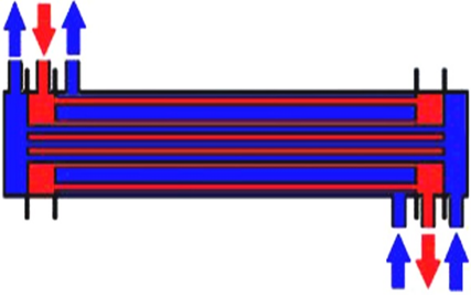
The CWST heat exchanger uses 3 fluids in counter-current; one of them is hot and flows between the other two fluids i.e. passing through the first inlet distributor then the shell and finally the first outlet distributor. The other two fluids are cold, one of them has to pass directly into the shell and then through the outlet nozzle. The second has to pass through the last inlet distributor then the first inlet distributor, and exits through the last outlet distributor (Figures 7 and 8). This configuration is used to minimize heat loss outside the heat exchanger.
The STHE and the CWST heat exchanger are simulated using identical conditions; however, the CWST heat exchanger is required to use half of the STHE's cold fluid flow rate for each of its fluids.
Figure 7. Representation of the hot (red) and cold (blue) fluids in transversal section of the CWST exchanger
Figure 8. Representation of the hot (red) and cold (blue) fluids in longitudinal section of the CWST exchanger
4.2 Mesh generation
To obtain good simulation results, it is important to make a mesh study that makes a compromise between the calculation accuracy and the necessary time that must be reduced.
In our simulations, an unstructured mesh with a combination of tetrahedral and hexahedral elements is used to accommodate the complex geometry of the exchangers. A fine mesh was used for the walls and regions close to the walls, and a coarse mesh was used for the remaining regions.
For the STHE with distributors, we studied four meshes, one of them is designated by “A1” and has 9468787 elements and 2292807 nodes, the second is designated by “B1” and has 7942061 elements and 1864633 nodes, the third is designated by “C1” and has 3758815 elements and 965267 nodes, and the forth is designated by “D1” and has 2129262 elements and 543322 nodes. In this mesh study it was concluded to take the results of the "C1" mesh which are obtained in a reasonable calculation time and give a difference with the "A1" mesh that does not exceed 2.9%.
In the same way as the first mesh study, four meshes were investigated for the CWST exchanger, the first is designated by “A2” and has 7700839 elements and 2035748 nodes, the second is designated by “B2” and has 4075584 elements and 1020824 nodes, the third is designated by “C2” and has 3475472 elements and 896818 nodes (Figure 9), and the forth is designated by “D4” and has 2350966 elements and 617851 nodes. In this second meshing study, it was decided to take the results of the "C2" mesh which are obtained with a reduced computation time, and that give a difference with the "A2" mesh which does not exceed 2.5%.
For the STHE without distributors, the results of 10506221 elements and 2660304 nodes were chosen because it was used only once for the validation which needs more precision. It should be noted that this mesh gives results that have a difference which does not exceed 1.5% between those of 3394039 elements and 891739 nodes.
Figure 9. Meshed geometry of the CWST heat exchanger
After several iterations we note the convergence of the calculation and we proceed to the collect of the data that are required to analyse and conclude on the performances of the studied exchangers.
We note that the overall heat transfer coefficient and the outlet temperatures resulting from the simulation of the shell-and-tube heat exchanger without distributors are almost identical to those calculated theoretically (Table 4); This confirms and validates the exchangers simulation that use common approaches and close geometries.
Table 4. Validation results of the STHE without distributors
|
Simulation |
Theoretical Calculation |
Differences (%) |
|
|
Tfs [K] |
313.285 |
312.659 |
0.2 |
|
Tcs [K] |
325.685 |
326.351 |
0.2 |
|
K [W/(m2.K)] |
167.865 |
159.955 |
4.948 |
With the temperature and flow conditions mentioned above, the two simulations of the CWST heat exchanger and the STHE with distributors were completed. This allowed us to obtain the necessary results, which are presented in the Table 4.
The CWST exchanger allows a heat transfer almost identical to that of the STHE from which it is derived and despite its reduced exchange surface. We can mention that pressure losses are minimised in the CWST exchanger so it can contribute to a reduction of its operating cost. It is also noticed that the volume copper is bigger in the shell-and-tube exchanger so it gives less tube mass in CWST exchanger, and can therefore contribute to the reduction of its manufacturing cost. For example, if we take the prices of raw materials on the market, such as the price of steel used for the shell, the price of copper used for the tubes, and the price of Plexiglas that can be used for the tube sheets, we will have a reduction of 13.3 % compared with the STHE.
We note that the average exchange surface is the average of the inner and the outer exchange surfaces of the copper tubes, and the percentage differences highlighted in Table 5 in red represent the advantages of the CWST exchanger over the STHE.
The slight difference in the outlet temperatures between the two STHE (with and without distributors) is probably due to the heat flow that takes place through the tube sheets of the exchanger with distributors and which is absent for the exchanger without distributors, as well as the probable increase in turbulence in the distributors which is caused by the increased singularities.
Table 5. Simulation results of the CWST exchanger and the STHE with distributors
|
CWST |
STHE with Distributors |
Differences (%) |
|
|
Tfs1 [K] |
314.174 |
- |
- |
|
Tfs2 [K] |
319.3963 |
316.8213 |
- |
|
Tcs [K] |
326.0031 |
325.8307 |
+0.052 |
|
ϕ [W] |
3434.8 |
3439.8 |
-0.145 |
|
Heat flux [W/m2] |
5304.64 |
4485.98 |
+15.43 |
|
Pressure losses [Pa] |
1538.61 |
1641.307 |
-6.674 |
|
ϕ / (pressure losses) [W/Pa] |
2.232 |
2.0295 |
+9.0725 |
|
Copper volume [m3] |
0.0006475 |
0.0007667 |
-18.41 |
|
Average exchange surface [m2] |
0.647508 |
0.766788 |
-18.41 |
6.2 Pressure distribution
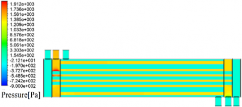
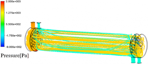
Figures 10-13 represent the relative pressure distribution inside the STHE and the CWST exchangers, and are obtained by two simulations with the same temperature and flow conditions as the validation step (25 l/min with 328 K for the inlet hot water. 2 l/min with 292 K for the inlet cold water of the STHE and the two cold water of the CWST).
It can be seen after the hot fluid enters through the inlet nozzle, that the pressure increases significantly in the lower part of the STHE distributor, and this increase is due to the shock of the fluid which is hitting the wall. This fact is also seen around the first tubes exposed to the flow and located in the hot fluid inlet distributor of the CWST exchanger.
It can also be noticed that the pressure distribution is globally greater in the STHE than in the CWST exchanger for the raison that there are more tubes in the first exchanger that flow greater mass flow rate.
The hot fluid has a greater flow rate than the cold fluid in the two studied exchangers, and this fact generates greater pressure inside the distributors and inside the tubes of the STHE. This same fact is found for the CWST exchanger where the pressure inside the first distributors and in the tubes connected to them is greater than the pressure of the fluid entering the shell, and the fluid entering through the last distributor.
Figure 10. Longitudinal section figure that represents pressure distribution of the CWST heat exchanger
Figure 11. Longitudinal section figure that represents pressure distribution of shell-and-tube exchanger
Figure 12. Streamline pressure distribution of the CWST exchanger
Figure 13. Streamline pressure distribution of the STHE
6.3 Velocity distribution
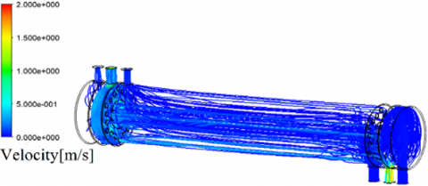
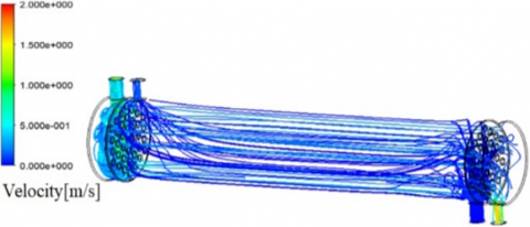
Figures 14-17 represent the velocity distribution of the fluid particles inside the STHE and the CWST exchangers, and are obtained by two simulations with the same temperature and flow conditions as the validation step.
It can be seen that the velocity is globally higher in the STHE than in the CWST heat exchanger, despite the use of the same flow rate of hot and cold fluids. And it is assumed that this reduction of the velocity can be due to the use of the large coaxial channel with 2276.5 mm2 of passage section. This channel flows a large part of the fluid compared to the 19 central tubes of the shell-and-tube exchanger that have 1491.5 mm2 of passage section, and therefore it reduces the flow rate in all the peripheral tubes, and also the mean velocity in the coaxial channel.
This difference of velocity distribution in the two exchangers is the main reason for the lower pressure drop in the CWST exchanger compared to the STHE.
In the inlet distributor of the STHE, the fluid velocity decreases as it gets closer to the lower extremity of this distributor, and this is primarily due to the fact that the fluid begins to be distributed into the first tubes close to the inlet nozzle and decreases in the lower part of the distributor. Secondly, the fluid is also slowed down by the low wall it hits, as demonstrated in the pressure distribution figure. This fact is also observed in the first inlet distributor of the CWST exchanger, where we can see that the fluid is slowed down by the tubes inside this distributor and flows primarily into the tubes close to the inlet nozzle. On the other hand, this decrease in velocity is not shown in the last inlet distributor because the flow rate is low.
Figure 14. Longitudinal section figure that represents the velocity distribution of the CWST exchanger
Figure 15. Longitudinal section figure that represents the velocity distribution of the STHE
Figure 16. Streamline velocity distribution of the CWST exchanger
Figure 17. Streamline velocity distribution of the STHE
6.4 Temperature distribution
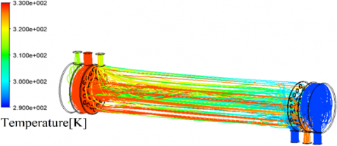
Figures 18-21 are obtained by two simulations based on the same temperature and flow conditions as the validation step and represent the temperature distribution inside the two studied exchangers.
Figure 18. Longitudinal section figure that represents the temperature distribution of the CWST exchanger
Figure 19. Longitudinal section figure that represents the temperature distribution of the STHE
Figure 20. Streamline temperature distribution of the CWST exchanger
Figure 21. Streamline temperature distribution of the STHE
It can be seen that the cold fluid in the STHE takes a short distance in the shell to warm up compared to the CWST exchanger, and after this the temperature tend to be constant in the shell. The temperature is globally cooler in the CWST exchanger than in the STHE, so it gives a greater temperature gradient in the first exchanger than in the second one.
We also notice that the temperatures of the hot fluid at the inlet and outlet nozzles of the CWST exchanger are almost similar to the temperatures of the hot fluid at the inlet and outlet nozzles of the shell-and-tube exchanger, this is why the heat transfer of the two exchangers are almost the same.
It is assumed that the concentration of the exchanged heat at the beginning of the cold fluid entry of the shell-and-tube is due to his larger exchange surface, and then this concentration decreased because of the close temperatures of the two fluids and the presence of less turbulence than in the CWST exchanger. The latter has a sufficient length of the shell, a higher turbulence and a temperature gradient that allow it to compensate the delay in the exchanged heat despite its reduced exchange surface, so it gives an almost identical exchanged heat for the two exchangers. This high turbulence of the CWST exchanger, which increases the heat flux, can be assumed to be caused by the presence of tubes inside the hot fluid distributor, as well as the use of more distributors which increases the singularities of the fluid particles compared to the STHE.
The outlet temperature of the cold fluid from the last outlet distributor is lower than the temperature of the fluid leaving through the shell nozzle, even though they have the same inlet temperature, is due to the fact that they don't cross the same path, and that as the path of the fluid entering through the outlet distributor is narrower, it would have a little more velocity than the shell fluid, and therefore cools down a little more.
6.5 Evolution of total pressure losses
The evolution of the total pressure losses of the shell-and-tube and the CWST exchangers as a function of the cold water volume flow rate is shown in Figure 22. This curve has been elaborated by fixing the hot flow rate at 25 l/min and the two hot and cold inlet temperatures at 328 K and 292 K.
It can be seen that the total pressure losses of the STHE is always higher than the CWST exchanger (also on the 2 l/min point) and that the difference between the two exchangers increases as the cold fluid flow rate increases.
Figure 22. Total pressure losses versus cold fluid volume flow rate curve
6.6 Evolution of the heat
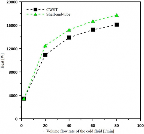
The evolution of the exchanged heat of the shell-and-tube and the CWST exchangers as a function of the volume flow rate of the cold water is shown in Figure 23, and it has been developed in the same way as the first curve.
It can be seen that the heat starts by being almost identical between the two exchangers for a cold fluid flow rate of 2 l/min, then as this flow rate increases, it can be seen that the heat from the STHE becomes greater.
Figure 23. Heat versus cold fluid volume flow rate curve
6.7 Evolution of the heat flux
The evolution of the heat flux versus the cold fluid volume flow rate of STHE and the CWST exchangers has been elaborated with the data of the heat curve and shown in Figure 24.
It can be seen that the heat flux is often greater in the CWST exchanger, also for the 20 l/min point where it is almost identical with the STHE, and it is noticed that by increasing the volume flow rate from this point the difference between the two exchangers becomes greater. This heat flux advantage of the CWST exchanger which is probably increased by his high turbulence, may allow designing other geometries with larger exchange surfaces and improving the exchanged heat compared to the STHE.
Figure 24. Heat flux versus cold fluid volume flow rate curve
Figure 25. Ratio of heat to total pressure losses versus cold fluid volume flow rate curve
Figure 26. Overall heat transfer coefficient versus cold fluid volume flow rate curve
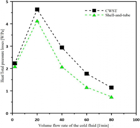
6.8 Evolution of the ratio of heat to total pressure losses
The evolution curve in Figure 25 represents the ratio of heat to total pressure losses as a function of the cold water volume flow rate of the STHE and the CWST exchangers, and was constructed with the data of the two previous curves of the pressure losses and the heat.
It can be seen that the ratio of heat to the total pressure losses is always greater for the CWST exchanger, and that the highest value for both exchangers is represented by the 20 l/min flow rate. This ratio allows us to assert that providing the same flow rate for CWST as the STHE, a better yield of heat transfer can be obtained (i.e. a better exchanged heat for less pressure drop). And this yield indicates the reduction of CWST operating cost compared to the STHE.
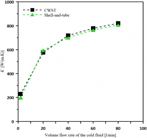
6.9 Evolution of the overall heat transfer coefficient
Figure 26 shows the evolution of the overall heat transfer coefficient of the CWST and the STHE, and was developed with the heat transfers corresponding to each flow rate by using the following equation [39]:
$K=\frac{\phi }{{{S}_{m}}\cdot \left( T{{c}_{m}}-T{{f}_{m}} \right)}$ (30)
Tcm and Tfm represent the average temperature of the hot fluid and the average temperature of the cold fluid for each of the two exchangers, and can be calculated as follows [45]:
$T{{c}_{m}}=\frac{T{{c}_{e}}+T{{c}_{s}}}{2}$ (31)
For the STHE:
$T{{f}_{m}}=\frac{T{{f}_{e}}+T{{f}_{s}}}{2}$ (32)
For the CWST heat exchanger:
$T{{f}_{m}}=\frac{2T{{f}_{e}}+T{{f}_{s1}}+T{{f}_{s2}}}{4}$ (33)
In Figure 26, it can be seen that the overall heat transfer coefficient of the CWST exchanger is higher than the shell-and-tube exchanger except for the 20 l/min flow rate where it is slightly lower than the STHE. This increase in the overall heat transfer coefficient for the CWST heat exchanger shows the potential of the latter to improve heat transfer, if its geometry is improved by increasing its exchange surface.
In this article, the CWST exchanger was studied in comparison with the shell-and-tube exchanger from which it is derived, and after validating the simulations, the following conclusions were reached:
·With a flow rate of 25 l/min for the hot water and 2 l/min for the cold water, the CWST heat exchanger transfers the same heat as the shell-and-tube heat exchanger (with distributors), but with less pressure drop.
·CWST heat exchanger produces less pressure drop than shell-and-tube heat exchanger with all studied flow rates.
·Despite its reduced heat exchange surface, the CWST exchanger gives a higher heat flux and a higher ratio of heat to pressure drop than the shell-and-tube with all the studied flow rates, which demonstrates its ability to improve heat transfer while generating less pressure losses.
·The CWST exchanger gives a higher overall heat transfer coefficient than the shell-and-tube exchanger for the majority of studied flow rates.
·The studied CWST exchanger uses less copper tubes and can contribute to the reduction of its manufacturing cost compared to the shell-and-tube exchanger.
It should be noticed that the design of the CWST heat exchanger can be improved in the future, by developing a geometry with optimised design parameter, by adding baffles and fins to its cavities, and by changing the shape of the copper tubes. In addition, more flow rates can be investigated, and other fluids can be used, such as nanofluids, to enhance its performances.
|
Cf |
Coefficient of friction |
|
Cp |
Heat capacity coefficient at constant pressure [J/(kg. K)] |
|
D |
Cross-diffusion term [kg/(m. s3)] |
|
di |
Inside diameter of a tube [m] |
|
do |
Outside diameter of a tube [m] |
|
Ds |
Inside diameter of the shell [m] |
|
e |
Thickness of a tube [m] |
|
G |
Surface flow rate [kg/(m2.s)] |
|
Gt |
Generation of k or $\boldsymbol{\omega}$ [kg/m.s3)] |
|
h |
Convection coefficient [W/(m2.K)] |
|
k |
Turbulent kinetic energy [m2/s2] |
|
K |
Overall heat transfer coefficient [W/(m2.K)] |
|
L |
Length of the shell [m] |
|
Nt |
Number of tubes |
|
Nu |
Nusselt number |
|
P |
Pressure [Pa] |
|
Pr |
Prandtl number |
|
PR |
Ratio of the pitch to the outside diameter of a tube |
|
Pt |
Pitch [m] |
|
qm |
Mass flow rate [kg/s] |
|
Re |
Reynolds number |
|
S |
Section [m2] |
|
St |
User-defined source term [kg/m s3)] |
|
t |
Time [s] |
|
T |
Temperature [K] |
|
Tc |
Temperature of the hot fluid [K] |
|
Tf |
Temperature of the cold fluid [K] |
|
u |
Velocity [m/s] |
|
x |
Coordinate [m] |
|
Y |
Dissipation of k or ω [kg/(m.s3)] |
|
Greek symbols |
|
|
ε |
Efficiency |
|
μ |
Dynamic viscosity [Pa.s] |
|
ρ |
Density [kg/m3] |
|
ϕ |
Heat [W] |
|
ω |
Specific dissipation rate [1/s] |
|
Subscripts |
|
|
c |
Hot fluid |
|
e |
Input |
|
eq |
Equivalent |
|
ext |
Fluid outside the tubes |
|
f |
Cold fluid |
|
i |
Fluid inside the tubes |
|
j |
Column element of a tensor |
|
k |
Related to the turbulent kinetic energy |
|
m |
Average |
|
max |
Maximum |
|
min |
Minimum |
|
s |
Output |
|
s1 |
Outlet nozzle of the last distributor for CWST |
|
s2 |
Outlet nozzle connected to the shell for CWST also refers to the outlet nozzle of the Shell-and- tube exchanger (used for comparison) |
|
t |
Row element of a tensor |
|
tube |
Material of the tube |
|
wet |
Wetted section |
|
ω |
Related to the specific dissipation rate |
|
Abbreviation |
|
|
CWST |
The coaxial with shell-and-tube heat exchanger |
|
SIMPLE |
The coaxial with shell-and-tube heat exchanger |
|
STHE |
Shell-and-tube heat exchanger |
|
NTU |
Number of transfer units |
[1] Tan, X.H., Zhu, D.S., Zhou, G.Y., Yang, L. (2013). 3D numerical simulation on the shell side heat transfer and pressure drop performances of twisted oval tube heat exchanger. International Journal of Heat and Mass Transfer, 65: 244-253. https://doi.org/10.1016/j.ijheatmasstransfer.2013.06.011
[2] Zhang, X.X., Wei, G.H., Sang, Z.F. (2007). Experimental research of heat transfer and flow friction properties in twisted tube heat exchanger. Huaxue Gongcheng (Chemical Engineering), 35(2): 17-20.
[3] Dizaji, H.S., Jafarmadar, S., Abbasalizadeh, M., Khorasani, S. (2015). Experiments on air bubbles injection into a vertical shell and coiled tube heat exchanger; exergy and NTU analysis. Energy Conversion and Management, 103: 973-980.https://doi.org/10.1016/j.enconman.2015.07.044
[4] Genić, S.B., Jaćimović, B.M., Jarić, M.S., Budimir, N.J., Dobrnjac, M.M. (2012). Research on the shell-side thermal performances of heat exchangers with helical tube coils. International Journal of Heat and Mass Transfer, 55(15-16): 4295-4300. https://doi.org/10.1016/j.ijheatmasstransfer.2012.03.074
[5] Zhang, J.F., Guo, S.L., Li, Z.Z., Wang, J.P., He, Y.L., Tao, W.Q. (2013). Experimental performance comparison of shell-and-tube oil coolers with overlapped helical baffles and segmental baffles. Applied Thermal Engineering, 58(1-2): 336-343. https://doi.org/10.1016/j.applthermaleng.2013.04.009
[6] Zhang, J.F., He, Y.L., Tao, W.Q. (2009). 3D numerical simulation on shell-and-tube heat exchangers with middle-overlapped helical baffles and continuous baffles–Part I: Numerical model and results of whole heat exchanger with middle-overlapped helical baffles. International Journal of Heat and Mass Transfer, 52(23-24): 5371-5380. https://doi.org/10.1016/j.ijheatmasstransfer.2009.07.006
[7] Zhang, L., Xia, Y., Jiang, B., Xiao, X., Yang, X. (2013). Pilot experimental study on shell and tube heat exchangers with small-angles helical baffles. Chemical Engineering and Processing: Process Intensification, 69: 112-118. https://doi.org/10.1016/j.cep.2013.03.005
[8] Xiao, X., Zhang, L., Li, X., Jiang, B., Yang, X., Xia, Y. (2013). Numerical investigation of helical baffles heat exchanger with different Prandtl number fluids. International Journal of Heat and Mass Transfer, 63: 434-444. https://doi.org/10.1016/j.ijheatmasstransfer.2013.04.001
[9] Vukić, M.V., Tomić, M.A., Živković, P.M., Ilić, G.S. (2014). Effect of segmental baffles on the shell-and-tube heat exchanger effectiveness. Hemijska Industrija, 68(2): 171-177. https://doi.org/10.2298/HEMIND130127041V
[10] Saffarian, M.R., Fazelpour, F., Sham, M. (2019). Numerical study of shell and tube heat exchanger with different cross-section tubes and combined tubes. International Journal of Energy and Environmental Engineering, 10: 33-46. https://doi.org/10.1007/s40095-019-0297-9
[11] Li, N., Chen, J., Cheng, T., Klemeš, J.J., Varbanov, P.S., Wang, Q., Yang, W., Zeng, M. (2020). Analysing thermal-hydraulic performance and energy efficiency of shell-and-tube heat exchangers with longitudinal flow based on experiment and numerical simulation. Energy, 202: 117757. https://doi.org/10.1016/j.energy.2020.117757
[12] El-Said, E.M., Elsheikh, A.H., El-Tahan, H.R. (2021). Effect of curved segmental baffle on a shell and tube heat exchanger thermohydraulic performance: Numerical investigation. International Journal of Thermal Sciences, 165: 106922. https://doi.org/10.1016/j.ijthermalsci.2021.106922
[13] Slimene, M.B., Poncet, S., Bessrour, J., Kallel, F. (2022). Numerical investigation of the flow dynamics and heat transfer in a rectangular shell-and-tube heat exchanger. Case Studies in Thermal Engineering, 32: 101873. https://doi.org/10.1016/j.csite.2022.101873
[14] Ali, M.R., Al-Khaled, K., Hussain, M., Labidi, T., Khan, S.U., Kolsi, L., Sadat, R. (2022). Effect of design parameters on passive control of heat transfer enhancement phenomenon in heat exchangers–A brief review. Case Studies in Thermal Engineering, 2022: 102674. https://doi.org/10.1016/j.csite.2022.102674
[15] Yang, J., Liu, W. (2015). Numerical investigation on a novel shell-and-tube heat exchanger with plate baffles and experimental validation. Energy Conversion and Management, 101: 689-696. https://doi.org/10.1016/j.enconman.2015.05.066
[16] Chen, J., Li,N., Ding, Y., Klemeš, J.J., Varbanov, P.S., Wang, Q., Zeng, M. (2020). Experimental thermal-hydraulic performances of heat exchangers with different baffle patterns. Energy, 205: 118066. https://doi.org/10.1016/j.energy.2020.118066
[17] Wang, X., Liang, Y., Sun, Y., Liu, Z., Liu, W. (2019). Experimental and numerical investigation on shell-side performance of a double shell-pass rod baffle heat exchanger. International Journal of Heat and Mass Transfer, 132: 631-642. https://doi.org/10.1016/j.ijheatmasstransfer.2018.12.046
[18] Liu, J.J., Liu, Z.C., Liu, W. (2015). 3D numerical study on shell side heat transfer and flow characteristics of rod-baffle heat exchangers with spirally corrugated tubes. International Journal of Thermal Sciences, 89: 34-42. https://doi.org/10.1016/j.ijthermalsci.2014.10.011
[19] Ji, J., Ge, P., Bi, W. (2016). Numerical analysis on shell-side flow-induced vibration and heat transfer characteristics of elastic tube bundle in heat exchanger. Applied Thermal Engineering, 107: 544-551.https://doi.org/10.1016/j.applthermaleng.2016.07.018
[20] Bougriou, C., Baadache, K. (2010). Shell-and-double concentric-tube heat exchangers. Heat and Mass Transfer, 46: 315-322. https://doi.org/10.1007/s00231-010-0572-z
[21] Trang, N.V., Trung, D.T., Dzung, D.V. (2017). Experimental study of alternative minichannel heat exchanger for scooter radiator. International Journal of Emerging Research in Management & Technology, 6(4): 46-50. https://doi.org/10.23956/ijermt/V6N4/116
[22] Lozano, A., Barreras, F., Fueyo, N., Santodomingo, S. (2008). The flow in an oil/water plate heat exchanger for the automotive industry. Applied Thermal Engineering, 28(10): 1109-1117. https://doi.org/10.1016/j.applthermaleng.2007.08.015
[23] ] Khairul, M.A., Alim, M.A., Mahbubul, I.M., Saidur, R., Hepbasli, A., Hossain, A. (2014). Heat transfer performance and exergy analyses of a corrugated plate heat exchanger using metal oxide nanofluids. International Communications in Heat and Mass Transfer, 50: 8-14. https://doi.org/10.1016/j.icheatmasstransfer.2013.11.006
[24] Elias, M.M., Shahrul, I.M., Mahbubul, I.M., Saidur, R., Rahim, N.A. (2014). Effect of different nanoparticle shapes on shell and tube heat exchanger using different baffle angles and operated with nanofluid. International Journal of Heat and Mass Transfer, 70: 289-297. https://doi.org/10.1016/j.ijheatmasstransfer.2013.11.018
[25] Leong, K.Y., Saidur, R., Mahlia, T.M.I., Yau, Y.H. (2012). Modeling of shell and tube heat recovery exchanger operated with nanofluid based coolants. International Journal of Heat and Mass Transfer, 55(4): 808-816. https://doi.org/10.1016/j.ijheatmasstransfer.2011.10.027
[26] Elias, M.M., Miqdad, M., Mahbubul, I.M., Saidur, R., Kamalisarvestani, M., Sohel, M.R., Hepbasli, A., Rahim, N.A., Amalina, M.A. (2013). Effect of nanoparticle shape on the heat transfer and thermodynamic performance of a shell and tube heat exchanger. International Communications in Heat and Mass Transfer, 44: 93-99. https://doi.org/10.1016/j.icheatmasstransfer.2013.03.014
[27] Philip, J., Shima, P.D., Raj, B. (2008). Nanofluid with tunable thermal properties. Applied Physics Letters, 92(4): 043108. https://doi.org/10.1063/1.2838304
[28] Yu, W., Xie, H., Wang, X., Wang, X. (2011). Significant thermal conductivity enhancement for nanofluids containing grapheme nanosheets. Physics Letters A, 375(10): 1323-1328. https://doi.org/10.1016/j.physleta.2011.01.040
[29] Ajeeb, W., da Silva, R.R.T., Murshed, S.S. (2023). Experimental investigation of heat transfer performance of Al2O3 nanofluids in a compact plate heat exchanger. Applied Thermal Engineering, 218: 119321. https://doi.org/10.1016/j.applthermaleng.2022.119321
[30] Dasore, A., Konijeti, R., Prakash, B.O., Yelamasetti, B. (2024). Numerical and empirical simulation of fluid flow in a spiral plate heat exchanger with Nusselt number correlation development. International Journal on Interactive Design and Manufacturing (IJIDeM), 18: 3103-3113. https://doi.org/10.1007/s12008-023-01454-x
[31] Touatit, A., Bougriou, C. (2018). Optimal diameters of triple concentric-tube heat exchangers. International Journal of Heat and Technology, 36(1): 367-375. https://doi.org/10.18280/ijht.360149
[32] Xie, G.N., Wang, Q.W., Zeng, M., Luo, L.Q. (2007). Heat transfer analysis for shell-and-tube heat exchangers with experimental data by artificial neural networks approach. Applied Thermal Engineering, 27(5-6): 1096-1104. https://doi.org/10.1016/j.applthermaleng.2006.07.036
[33] Fettaka, S., Thibault, J., Gupta, Y. (2013). Design of shell-and-tube heat exchangers using multiobjective optimization. International Journal of Heat and Mass Transfer, 60: 343-354. https://doi.org/10.1016/j.ijheatmasstransfer.2012.12.047
[34] Guo, J., Cheng, L., Xu, M. (2009). Optimization design of shell-and-tube heat exchanger by entropy generation minimization and genetic algorithm. Applied Thermal Engineering, 29(14-15): 2954-2960.https://doi.org/10.1016/j.applthermaleng.2009.03.011
[35] Şahin, A.Ş., Kılıç, B., Kılıç, U. (2011). Design and economic optimization of shell and tube heat exchangers using Artificial Bee Colony (ABC) algorithm. Energy Conversion and Management, 52(11): 3356-3362. https://doi.org/10.1016/j.enconman.2011.07.003
[36] Guo, J., Xu, M., Cheng, L. (2009). The application of field synergy number in shell-and-tube heat exchanger optimization design. Applied Energy, 86(10): 2079-2087. https://doi.org/10.1016/j.apenergy.2009.01.013
[37] Fesanghary, M., Damangir, E., Soleimani, I. (2009). Design optimization of shell and tube heat exchangers using global sensitivity analysis and harmony search algorithm. Applied Thermal Engineering, 29(5-6): 1026-1031. https://doi.org/10.1016/j.applthermaleng.2008.05.018
[38] Wang, D., Zhang, H., Wang, G., Yuan, H., Peng, X. (2023). Experimental and numerical study on the heat transfer and flow characteristics of convex plate heat exchanger based on multi-objective optimization. International Journal of Heat and Mass Transfer, 202: 123755. https://doi.org/10.1016/j.ijheatmasstransfer.2022.123755
[39] Kakac, S., Liu, H., Pramuanjaroenkij, A. (2020). Heat Exchangers: Selection, Rating, and Thermal Design. CRC Press. https://doi.org/10.1201/9781420053746
[40] Amiroudine, S., Battaglia, J. L. (2011). Mécanique des Fluides. Dunod.
[41] Prończuk, M., Krzanowska, A. (2021). Experimental investigation of the heat transfer and pressure drop inside tubes and the shell of a minichannel shell and tube type heat exchanger. Energies, 14(24): 8563. https://doi.org/10.3390/en14248563
[42] Incropera, F.P., Dewitt, D.P., Bergman, T.L., Lavine, A.S. (2007). Fundamentals of Heat and Mass Transfer. John Wiley & Sons.
[43] Arani, A.A.A., Moradi, R. (2019). Shell and tube heat exchanger optimization using new baffle and tube configuration. Applied Thermal Engineering, 157: 113736. https://doi.org/10.1016/j.applthermaleng.2019.113736
[44] Zhang, L., Che, D. (2011). Turbulence models for fluid flow and heat transfer between cross-corrugated plates. Numerical Heat Transfer, Part A: Applications, 60(5): 410-440. https://doi.org/10.1080/10407782.2011.600583
[45] Kasumu, A.S., Nassar, N.N., Mehrotra, A.K. (2017). A heat-transfer laboratory experiment with shell-and-tube condenser. Education for Chemical Engineers, 19: 38-47. https://doi.org/10.1016/j.ece.2017.03.002