Salwan S. Sabry*![]() | Ahmed Nasser B. Alsammak
| Ahmed Nasser B. Alsammak![]()
© 2024 The authors. This article is published by IIETA and is licensed under the CC BY 4.0 license (http://creativecommons.org/licenses/by/4.0/).
OPEN ACCESS
This article introduces an isolated three-phase six-pulse rectifier using a solid-state transformer. The line frequency utility grid voltage is modulated by a frequency boost converter. This converter exists two parts. The first part is the rectifier section, and the second one is the inverter section. Then after, three-phase diode rectifier is powered by the medium frequency transformer 2 kHz to shrink the transformer size upto 20% or even 10% depensing to the frequency operating range for silicon steel core materials. The aim of this study is to shrink the occupied size of the rectifier using a higher frequency transformer. The study realizes that the grid line current has the same frequency contents as a regular three phase rectifier. In other words, the presented idea results in smaller weight and size while sustaining the performance of input current total harmonic distortion THD=31%. High power density power electronics converter would be extremely valuable for applications such as electric vehicle railways and aircraft. The proposed approach is reliable and easy to use. The solid-state transformer contributes to isolating and improving the overall converter's power density. Simulation results for the 16 kW converter were verified using MATLAB Simulink.
higher frequency solid state transformer, isolated three-phase, rectifier
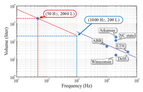
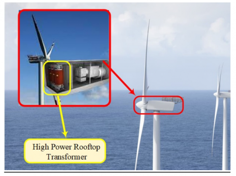
Nowadays, worldwide the demand on DC power supplies is increasing rapidly, especially for automotive, railway, aircraft, and data center applications. The value of the global semiconductor rectifiers market is predicted to hit $6.6 billion by 2026 [1]. Three phase conventional diode rectifier is one of the most trusted and popular converters due to its high reliability and durability [2-6]. However, the conventional three-phase rectifier utilizes conventional line frequency transformer (50/60) Hz for isolation purposes. The use of a conventional transformer has a negative consequence on the total power density of the three-phase rectifier. The power density is given by Eq. (1) [7]. It is ratio of the total power process through a converter to the total volume occupied by that power converter. Figure 1 illustrated the relationship between the occupied by transformer’s core with its running frequency [7]. High power density implies less footprint of power electronics converters [8]. For automotive and aircraft applications, high power density means reduced transport fuel consumption. Magnetic components such as transformers and inductors have the major footprint for the power electronics converter [9]. A higher power density is achieved by increasing the transformer's running frequency. Despite its smaller core cross-section area, the transformer core still produces the same amount of flux lines. Figure 1 shows A 1MVA silicone steel (Si) core transformer's volume shrinks from (2000 to 200) liter if the transformer’s core running frequency is raised from (50 to 1 kHz) respectively [7]. Renewable energy resources such as solar and wind turbines are the most promising energies worldwide. For more than a century, transformers have formed the backbone of electrical grids. However, as the world seeks to address the issue of climate change by expanding the utilization of renewable energy sources such as wind turbine farms and solar photovoltaic stations, new developments in transformer technology will play a significant role in this effort. In ocean depths where fixed-foundation turbines are impractical, floating wind farms, which comprise of wind turbines installed on floating structures, are ideally suited. They may vastly expand the amount of ocean that can be used for offshore wind farms across the world. If a wind farm has to have transformers, the best place for them to be inside the wind turbine tower, as shown in Figure 2 [10].
Figure 1. Transformers' core occupied with operation frequency [7]
The U.S. Department of Energy presented a vision 20% wind energy by 2030 to motivate the developing wind power [11]. Three-phase, six-pulse and multi-pulse converters are extensively used for high-power applications such as wind turbine and high voltage direct current HVDC [12-16]. However, the major drawback of these topologies is the low power density due to the use of a hefty line frequency transformer. Moreover, the traditional transformers such as the On-Load Tap OLTC Changing have some sort of low response [17].
Power Density $=\frac{\text { Total power process }(w)}{\text { Total volume ocupied }(\text { Liter })}$ (1)
Figure 2. Off-shore rooftop wind turbine transformer proposed by ABB [10]
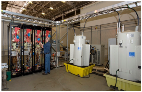
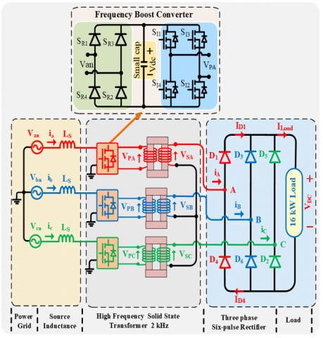
A solid-state transformer combines a power electronics converter with high-frequency transformer to perform voltage transformation, isolation, and extra regulation. The use of solid-state transformers reduces the hefty of magnetic components and allows for finer levels of control. However, these functionalities are unavailable from line frequency transformers. The solid-state transformers have become more popular due to the use of advanced power semiconductors such as Silicon Carbide SiC and Gallium Nitride Gan. Many applications can be benefited from solid-state transformers because of their adaptability and ease of control [18-23]. General Electric GE proposed and designed 1 MVA, 20 kHz solid state transformer. Their proposal was compared with a regular transformer in size and weight. The proposed is illustrated in Figure 3 [24]. The outcome results proved better power density for their proposal. In response to the power density concerns, the presented study presents an isolated six-pulse diode converter with the use of solid-state transformer, as shown in Figure 4.
The proposed idea indicates that the power density can be enhanced without sacrificing the performance of the six-pulse rectifier. In this paper, a design example for three phase six-pulse rectifier using a high frequency (2 kHz) solid state transformer is discussed. Extensive Matlab simulation analysis is explained in details. The presented concept offers advantages as listed below:
-The presented topology is robust and performed as a regular isolated three-phase rectifier.
-The input utility current has the same quality as a regular six-pulse rectifier.
-Using a frequency boost converter can give more resilience to control the power flow.
Figure 3. General Electric prototype comparison between solid-state transformer and traditional one [24]
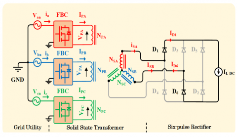
Figure 4. Proposed concept of three phase six-pulse rectifier using high frequency solid state transformer
The proposal for a three-phase six-pulse rectifier with a high-frequency solid state transformer is seen in Figure 4. There are three sections of the suggested idea.
2.1 Frequency boost converter
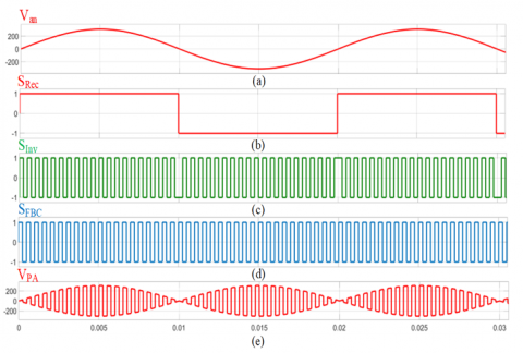
Figure 4 shows the per-phase frequency boost converter FBC. Each converter involves a rectification section, an inversion section. The rectification part has a 50 Hz rectification function SRec, while the inversion part has a 2 kHz inversion function SInv, as shown in Figure 5. The converter input voltage frequency is 50 Hz, and its output voltage frequency is 2 kHz. The main job of this converter is to elevate the frequency voltage that would be linked to the transformer input side and process the power flowing from the grid to the six-pulse rectifier. For the second and third phases, their converter output voltages would be identical, but they would be displaced by 120°.
Figure 5. Frequency boost converter operating mechanism: (a) Primary line frequency (50 Hz) input voltage Van; (b) Rectification function SRec; (c) Inversion function SInv; (d) Function of frequency boost converter SFBC; (e) High frequency (2 kHz) primary voltage VPA for phase ‘A’
2.2 Higher frequency isolation
The high-frequency transformer is the second portion of the proposed system. This transformer has been connected in star for both the main and secondary ends (see Figure 4). Core materials include silicon steel, amorphous, nanocrystalline, and ferrite, among others, could be used. However, the silicon steel core is the appropriate choice for high-power applications and optimally utilizes above the running frequency of 2 kHz, due to its cheap cost and acceptable core losses [24-31].
2.3 Three-phase diode rectifier
The last section of this proposal is a six-pulse diode rectifier wired to the secondary of higher frequency isolation, as demonstrated in Figure 4. It is preferable for each diode in the six-pulse rectifier to be used of silicon carbide due to its low loss.
The major harmonics content of electrical input currents (ia, ib, ic) for the conventional six-pulse diode rectifier is well known (5th, 7th, 11th, 13th, etc.) [2, 4]. In this section, depth analysis and math derivation show that the current grid quality for the presented idea and a conventional six-pulse rectifier with the use of a regular transformer are totally identical. In order to derive mathematical equations for the input current ia, the output load current IL DC for the rectifier is assumed to be smooth DC (see Figure 6). The comprehensive mathematical analysis is applied to the first phase, as shown in Figure 6. IPA is the primary transformer winding current, and SFBC is the frequency boost converter switching function (see Figure 5). To acquire the relationship between IPA and the secondary side currents of the transformer ISA, the transformer volt-ampere balanced between the primary and secondary sides should be used, as explained in Eq. (2). From Figure 6, it can be observed that ISA and ISB as written in Eqs. (3) and (4):
$i_a=S_{F B C} \times I_{P A}$ (2)
$N_{P A} \cdot I_{P A}=N_{S A} \cdot I_{S A}+N_{S B} \cdot I_{S B}$ (3)
$I_{S A}=I_{D 1}$ (4)
$I_{S B}=-I_{D 6}$ (5)
Since the transformer turns ratio is one, so by substituting Eqs. (4) and (5) into Eq. (3) to get:
$I_{P A}=I_{D 1}-I_{D 6}$ (6)
The DC load current ILDC goes through ID1 and ID6, shaping the primary current IPA as a quasi-square wave written by Eq. (7):
$S_{q u s i}(w t)=\sum_{n=1,5,7,11,13, \ldots}^{\infty}\left(\frac{4 \times I_{L D C}}{n \pi} \cos \left(\frac{n \pi}{6}\right)\right) \sin (n w t)$ (7)
The frequency boost converter’s switching function SFBC is equal to SRec multiplied by SInv (see Figure 5 and Eqs. (8)-(10)). The wHF is the boost frequency converter’s operating frequency 2 kHz:
$S_{\text {Rec }}=\left(\frac{4}{\pi}\right) \sum_{n=1,3,5, \ldots}^{\infty}\left(\frac{1}{n}\right) \sin (n w t)$ (8)
$S_{I n v}=\sum_{n=1,3,5, \ldots}^{\infty}\left(\frac{1}{n}\right) \sin \left(n w_{H F} t\right)$ (9)
$\begin{gathered}S_{F B C}=S_{R e c} \times S_{I n v}=\left(\frac{4}{\pi}\right) \sum_{n=1,3,5, \ldots}^{\infty}\left(\frac{1}{n}\right) \sin (n \pi D) \sin \left(n w_{H F} t\right)\end{gathered}$ (10)
Furthermore, IPA has to respond to the whole switching function SFBC. Due to the influence of SFBC, the diode currents (ID1, ID6) would be written by Eqs. (11) and (12):
$I_{D 1}=S_{F B C} \times S_{\text {quai }}(w t)$ (11)
$I_{D 6}=S_{F B C} \times S_{\text {quai }}\left(w t-\frac{2 \pi}{3}\right)$ (12)
Substituting Eqs. (11) and (12) into Eq. (6) gives:
$I_{P A}=\left[S_{q u a i}(w t)-S_{q u a i}\left(w t-\frac{2 \pi}{3}\right)\right] \times S_{F B C}$ (13)
Substituting Eq. (11) into Eq. (2):
$\begin{gathered}i_a=\left[S_{F B C}\right]^2\left(\frac{2 \sqrt{3} I_{L D C}}{\pi}\left[\sin (w t)-\frac{1}{5} \sin (5 w t)-\right.\right. \left.\left.\frac{1}{7} \sin (7 w t)+\frac{1}{11} \sin (11 w t)+\cdots . e t c\right]\right)\end{gathered}$ (14)
When the duty ratio D of the frequency boost converter is (50%), this implies:
$\begin{gathered}{\left[S_{F B C}\right]^2=\left\lceil\frac{4}{\pi} \sum_{n=1,3,5, \ldots}^{\infty}\left(\frac{1}{n}\right) \sin (n \pi D) \sin \left(n w_{H F} t\right)\right]^2} =1.0\end{gathered}$ (15)
The phase ‘A’ input current ia would be:
$i_a=\frac{2 \sqrt{3} I_{L D C}}{\pi}\left[\begin{array}{c}\sin (w t)-\frac{1}{5} \sin (5 w t) \\ -\frac{1}{7} \sin (7 w t)+\frac{1}{11} \sin (11 w t)-\cdots . e t c\end{array}\right]$ (16)
Evidently, the harmonics content of the input utility current ia for the presented topology, similar to the regular six-pulse rectifier.
Figure 6. Input current analysis ia for the presented topology in Figure 4
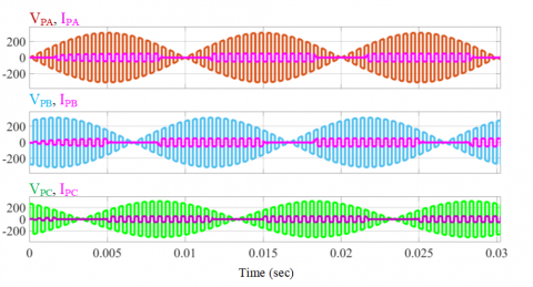
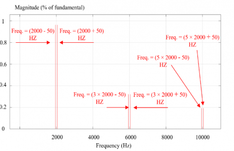
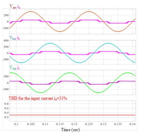
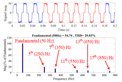
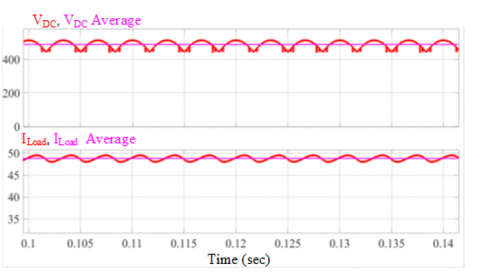
The suggested concept has been simulated using Matlab software in order to investigate the viability of the proposed system in Figure 4. The circuit parameters are listed in Table 1. The grid voltage is 380 volt line-to-line RMS value, 16 kW, 537 volt DC output voltage. Figure 5 explains the operating mechanism for the first phase frequency boost converter. The phase ‘A’ high-frequency voltage VPA is linked to the input of high-frequency transformer. For phase ‘B’ and ‘C’, the VPB, VPC would be the same, but they are displaced by 120 degrees. Figure 7 shows the voltages, and currents for the transformer’s primary side. The phase ‘A’ primary voltage VPA Fourier series analysis is shown in Figure 8. The influential frequency is around 2 kHz. Clearly, the transformer works at 2 kHz. Due to the high-frequency operation of the transformer, definitely the overall power density would be increased. Figure 9 illustrates the grid utility side voltages, currents, and the grid current ia’s THD. The frequency content for the utility input current ia is shown in Figure 10. It has 5th, 7th, 11th ,13th which is same as a conventional six-pulse rectifier. Moreover, the total harmonic distortion THD for the input current ia is 31% which is similar to a six-pulse rectifier using a conventional transformer. In other words, the performance of ia is unaffected by the proposed idea, while the power density is increased due to the utilization of a solid-state transformer. The DC side load voltage VDC and current ILoad are illustrated in Figure 11.
Figure 7. Voltages (VPA, VPB, VPC), currents (IPA, IPB, IPC) for the transformer's primary side
Figure 8. Fourier analysis for phase ‘A’ primary input voltage VPA
Figure 9. Grid utility voltages, currents (Van, ia, Vbn, ib, VCn, ic), and the total harmonics distortion for phase ‘A’ input current ia
Figure 10. The frequency contains for the utility input current ia
Figure 11. The DC side load voltage VDC and current ILoad
Table 1. Design example circuit parameters for Figure 4
|
Utility Gird’s Information |
Transformer’s Information |
FBC Switches Parameters Rating |
|
Vg=380 line-to-line RMs value |
Core material: Silicon steel type |
Rectifier bridge Peak current=52 A Peak voltage=311 V |
|
Source resistance=26 mΩ Source inductance=16.6 μH |
Operating frequency=2 k Hz |
Inverter bridge Peak current=52 A Peak voltage=311 V |
|
Frequency=50 Hz |
Turns ratio=1:1 |
|
|
Six-pulse diode rectifier |
|
DC Load side’s information |
|
Peak current=52 A |
|
RL=10 Ω L=20 mH |
|
Peak voltage=514 V |
|
IL=52 A |
|
Operating frequency=2 kHz |
|
VDC=540 V |
When the transformer works at line frequency (50/60) Hz, that tends to have negative consequences for the power density. The transformer’s (volume/ weight) can be reduced by increasing its operating frequency. The higher frequency of operating, the higher power density. There will be a major role for recent developments in transformer technology. Floating wind farms, which consist of wind turbines installed on floating platforms, are well suited for offshore sites at ocean depths where fixed-foundation turbines are not feasible. If a wind farm has to use transformers, installing them in the turbine’s tower is preferable. Solid state transformer could be the perfect solution to reduce the structure cost of the wind turbine tower and increase it reliability to achieve high efficiency for the total converter. The results of the presented idea demonstrate that the three phase rectifier's output DC voltage and utility input current quality are not affected by the usage of the solid-state transformer. However, the proposed approach swaps out the traditional line frequency transformer with a smaller solid state version, resulting in more power density for the isolated three-phase rectifier.
The authors would like to thank the University of Mosul, Iraq, for helping them with this work.
[1] DC power supplies market: Global industry trends, share, size, growth, opportunity and forecast 2022-2027. https://www.imarcgroup.com/dc-power-supplies-market.
[2] Wu, B., Narimani, M. (2017). High-Power Converters and AC Drives. John Wiley & Sons. https://doi.org/10.1002/9780471773719
[3] Mohan, N., Undeland, T.M., Robbins, W.P. (2003). Power Electronics: Converters, Applications, and Design. John Wiley & Sons.
[4] Jovcic, D. (2019). High Voltage Direct Current Transmission: Converters, Systems and DC Grids. John Wiley & Sons. https://doi.org/10.1002/9781118846704
[5] Hart, D.W., (2011). Power Electronics (Vol. 166). New York: McGraw-Hill.
[6] Smith, M.A., Atcitty, S. (2009). Power electronics reliability analysis (No. SAND2009-8377). Sandia National Laboratories (SNL), Albuquerque, NM, and Livermore, CA (United States). http://prod.sandia.gov/techlib/access-control.cgi/2009/098377.pdf.
[7] Ortiz, G., Biela, J., Kolar, J.W. (2010). Optimized design of medium frequency transformers with high isolation requirements. In IECON 2010-36th Annual Conference on IEEE Industrial Electronics Society, Glendale, AZ, USA, pp. 631-638. https://doi.org/10.1109/IECON.2010.5675240
[8] Sabry, S., Enjeti, P. (2020). High frequency integrated solid state transformer (SST) for utility interface of solar PV/Battery energy storage systems. In 2020 IEEE Applied Power Electronics Conference and Exposition (APEC), New Orleans, LA, USA, pp. 546-553. https://doi.org/10.1109/APEC39645.2020.9124199
[9] Burkart, R.M., Kolar, J.W. (2013). Comparative evaluation of SiC and Si PV inverter systems based on power density and efficiency as indicators of initial cost and operating revenue. In 2013 IEEE 14th Workshop on Control and Modeling for Power Electronics (COMPEL), Salt Lake City, UT, USA, pp. 1-6. https://doi.org/10.1109/COMPEL.2013.6626462
[10] ABB transformer for renewable energy applications 2019. https://searchext.abb.com/library/Download.aspx?DocumentID=9AKK107046A6498&LanguageCode=en&DocumentPartId=&Action=Launch.
[11] U.S. Department of Energy, 20% wind energy by 2030: “Increasing wind energy’s contribution to U.S. electricity supply” 2008. http://www.eere.energy.gov/windandhydro.
[12] Veilleux, E., Lehn, P.W. (2013). Interconnection of direct-drive wind turbines using a series-connected DC grid. IEEE Transactions on Sustainable Energy, 5(1): 139-147. https://doi.org/10.1109/TSTE.2013.2276616
[13] Breton, S.P., Moe, G. (2009). Status, plans and technologies for offshore wind turbines in Europe and North America. Renewable Energy, 34(3): 646-654. https://doi.org/10.1016/j.renene.2008.05.040
[14] Stark, G. (2009). Integration of offshore wind with modern HVDC technology. In Proceedings 8th International Workshop on Large-Scale Integration of Wind Power into Power Systems as well as on Transmission Networks for Offshore Wind Farms, Bremen, Germany.
[15] Arrillaga, J., Watson, N.R., Liu, Y.H. (2007). Flexible Power Transmission: The HVDC Options. John Wiley & Sons.
[16] ABB, Brochure: ABB goes Offshore, 2018. http://www. abb.com.
[17] Alkahdely, S.M.A., Alsammak, A.N.B. (2023). Non-limiting operation of the on-load tap changing transformer, and its effect on voltage stability, with regards to the nineveh electrical grid. Przeglad Elektrotechniczny, 99(4). https://doi.org/10.15199/48.2023.04.30
[18] Huber, J.E., Kolar, J.W. (2016). Solid-state transformers: On the origins and evolution of key concepts. IEEE Industrial Electronics Magazine, 10(3): 19-28. https://doi.org/10.1109/MIE.2016.2588878
[19] Huang, A.Q. (2016). Medium-voltage solid-state transformer: Technology for a smarter and resilient grid. IEEE Industrial Electronics Magazine, 10(3): 29-42. https://doi.org/10.1109/MIE.2016.2589061
[20] Liserre, M., Buticchi, G., Andresen, M., De Carne, G., Costa, L.F., Zou, Z.X. (2016). The smart transformer: Impact on the electric grid and technology challenges. IEEE Industrial Electronics Magazine, 10(2): 46-58. https://doi.org/10.1109/MIE.2016.2551418
[21] Ortiz, G., Biela, J., Bortis, D., Kolar, J.W. (2010). 1 Megawatt, 20 kHz, isolated, bidirectional 12kV to 1.2 kV DC-DC converter for renewable energy applications. In the 2010 International Power Electronics Conference-ECCE ASIA, Sapporo, Japan, pp. 3212-3219. https://doi.org/10.1109/IPEC.2010.5542018
[22] Ortiz, G., Leibl, M., Kolar, J.W., Apeldoorn, O. (2013). Medium frequency transformers for solid-state-transformer applications—Design and experimental verification. In 2013 IEEE 10th International Conference on Power Electronics and Drive Systems (PEDS), Kitakyushu, Japan, pp. 1285-1290. https://doi.org/10.1109/PEDS.2013.6527217
[23] She, X., Huang, A.Q., Burgos, R. (2013). Review of solid-state transformer technologies and their application in power distribution systems. IEEE Journal of Emerging and Selected Topics in Power Electronics, 1(3): 186-198. https://doi.org/10.1109/JESTPE.2013.2277917
[24] Madhusoodhanan, S., Tripathi, A., Patel, D., Mainali, K., Kadavelugu, A., Hazra, S., Subhashish BhattacharyaHatua, K. (2015). Solid-state transformer and MV grid tie applications enabled by 15 kV SiC IGBTs and 10 kV SiC MOSFETs based multilevel converters. IEEE Transactions on Industry Applications, 51(4): 3343-3360. https://doi.org/10.1109/TIA.2015.2412096
[25] Raju, R., Dame, M., Steigerwald, R. (2017). Solid-state transformers using silicon carbide-based modular building blocks. In 2017 IEEE 12th International Conference on Power Electronics and Drive Systems (PEDS), Honolulu, HI, USA, pp. 1-7. https://doi.org/10.1109/PEDS.2017.8289295
[26] Hurley, W.G., Wölfle, W.H. (2013). Transformers and Inductors for Power Electronics: Theory, Design and Applications. John Wiley & Sons. https://doi.org/10.1002/9781118544648
[27] Hitachi. (2015). Nanocrystalline soft magnetic material FINEMET. http://www.hilltech.com/pdf/hl-fm10-cFinemetIntro.pdf.
[28] Hitachi. (2016). Amorphous Alloys for Transformer Cores. http://www.metglas.com/assets/pdf/2605sa1.pdf.
[29] Ferch, M. (2016). Nanocrystalline core materials for modern power electronic design. http://www.magnetec.de/fileadmin/pdf/np_powerelectronic_e.pdf 215.
[30] Ferroxcube. (2016). Datasheet 3C94 Material Specification. http://www.ferroxcube.com/FerroxcubeCorporateReception/datasheet/3c94.pdf.
[31] Rylko, M.S., Lyons, B.J., Hayes, J.G., Egan, M.G. (2011). Revised magnetics performance factors and experimental comparison of high-flux materials for high-current DC–DC inductors. IEEE Transactions on Power Electronics, 26(8): 2112-2126. https://doi.org/10.1109/TPEL.2010.2103573