Nabeel S. Mahmood | Rafid Alboresha | Sadeq Oleiwi Sulaiman | Nadhir Al Ansari*
© 2022 IIETA. This article is published by IIETA and is licensed under the CC BY 4.0 license (http://creativecommons.org/licenses/by/4.0/).
OPEN ACCESS
One of the main concerns for engineers, during operation of dams, is uncontrolled seepage though the foundations of dams and hydraulic structures which is mainly resulted from poor geological conditions and lead to undermine erosion or piping that may endanger the safety of dam. In this study, numerical models were utilized to evaluate the excessive seepage problem underneath the spillway of Horan 2 Dam in Iraq as the seepage have led to dissipate storge and malfunction the dam. Two treatment methods were proposed to reduce the quantity of seepage by using a cutoff wall and a clay blanket. The results of the models indicated that the foundation of the spillway was unsafe against piping, as the calculated factor of safety was less than the allowable value. A clay blanket of 6 m long is recommended to sufficiently reduce the quantity of seepage and maintain the factor of safety within the allowable limits. As the cut off wall and clay blanket were used, the quantity of seepage decreased up to 73% and 96%, respectively, and the safety factor increased up to 100% and 110%, respectively. As discussed herein, using a clay blanket is the most cost-effective method comparing to using a cutoff wall.
dam safety, numerical modeling, seepage, cutoff wall, clay blanket, SEEP/W
Seepage analysis is a routine practice in designing of earth dams and hydraulic structures as any seepage problem may lead to great human and economic losses. Seepage analysis is focused on the determination of the flow lines, quantity of seepage, pore water pressure, seepage forces, seepage velocity, and the factor of safety against piping [1]. Uncontrolled seepage is a common problem that have been observed downstream of earth dams and hydraulic structures. As reported by the studies [2-4], statistics have indicated that 30 to 50% of earth dam failure cases have been caused by seepage through the body of the dam or the foundation. The increase in pore water pressure and seepage velocity, induced by the excessive flow underneath the structure, may cause soil piping in the foundation soil which represents a great danger on the structure stability. Many factors may affect the possibility of piping failure such as earthquakes and extreme operation conditions; however, geological condones are the main reason that have led to underground water flow [5-7]. Therefore, the study of the specific conditions of subsurface layers as well as the seismic conditions of the site is essential for the seepage analysis.
Effective elements against piping failure or to reduce excessive seepage are needed to prevent collapse or malfunction of dams and hydatic structures. Typically, treatment methods by using grouting curtain, excavation of the permeable materials, cutoff wall, and upstream impervious blanket are utilized to control seepage which result in considerable saving in the dimensions of the structure. Specifically, cutoff walls and upstream clay blankets are the most two cost-effective methods of treatment. These elements cause an increase the seepage path a decrease in the pore water pressure downstream the structure. As a result, the maximum hydraulic gradient will sharply decrease and a sufficient factor of safety against piping will be achieved. There is a direct proportion between the depth of the cutoff wall, or the length of the clay blanket and the factor of safety against piping. However, the cost of these construction should be considered when selecting the method of treatment [8-10].
With the aid of advanced software, numerical methods have been introduced to analyze complex seepage problems that may involve complicated boundary conditions and layered soils. Recently, iterative procedures based on the finite element methods have been widely utilized for the seepage analysis. Geo-Studio is one the advanced software that has been developed based on the finite element methods to analyze different seepage and slope stability problems. Specifically, SEEP/W model, which is one of the Geo-Studio models, has been an effective tool to determine the flow lines, quantity of seepage, pore water pressure, and hydraulic gradient of flow [11-15].
In the past four decays, many small earth dams have been constructed on the major valleys in the West Desert of Iraq for harvesting of seasonal runoff water. However, some of these dam projects have been constructed without detailed soil investigation programs [16]. One of these projects is Horan 2 Dam (H2), which is selected as a case study because an excessive seepage has been observed underneath the spillway. Since the construction of the dam, the spillway has experienced a performance issue stemming from an excessive seepage through the underlaid deposits layer. Numerical models were established by using SEEP/W to evaluate the effects of the current seepage on the performance and safety of the dam. The models also included an evaluation of the effects of using a cutoff wall and an upstream clay blanket to reduce the quantity of seepage. The purpose and contribution of this research is to thoroughly demonstrate the effect of uncontrolled seepage on the stability of dams and to propose solutions for the problem. For practical purposes, this evaluation is essential for engineers and practitioners who are dealing with the design, construction, and operation of small dams.
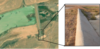
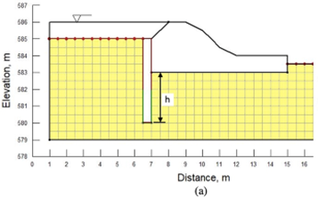
H2 Dam is an earthfall dam with a central clay core that was constructed on Wadi Horan in the West Desert of Iraq, about 10 km north west of Ruttba City, as shown in Figure 1. The dam was constructed in 2006 to be used for rainwater harvesting and groundwater recharge. The H2 Dam is zoned dam that consists of sand-gravel shells, clay core, and two filter layers, as shown in Figure 2. The details of the dam dismissions and the hydraulic characteristics are presented in Table 1. The conditions of the subsurface soils and rocks layers are shown in Figure 3. The spillway was constructed on a layer of loose deposits mixture which consists of sand gravel and silt with an average depth of 6 m. The deposits layer is underlined by a layer of dolomite and dolomitic limestone, as shown in Figure 4 which illustrates the typical cross section of the spillway and the subsurface soil. The quality of rock is hard with a very low value of permeability [17].
Figure 1. An aerial image of H2 Dam with a photograph of the spillway
Figure 2. The H2 Dam cross section (reproduced from [17])
Figure 3. The geological cross section of the H2 Dam site (reproduced from [17])
Table 1. Geometric and hydraulic values of the Dam ([17])
|
Property |
Value |
|
Crest level, m |
590 |
|
Spillway level, m |
586 |
|
Earth dam length, m |
480 |
|
Spillway length, m |
150 |
|
Crest width, m |
8 |
|
Maximum flood water level, m3 |
588 |
|
Maximum operation level, m3 |
586 |
|
Difference btw. crest and lowest bed level, m |
12 |
|
Dead storage level, m3 |
579 |
|
Storage at operation level, million m3 |
5.3 |
|
Reservoir surface area at operation level, km2 |
1.8 |
|
Discharge of bottom outlet, m3/s |
2 |
Figure 4. A typical cross section of the spillway and the subsurface layers (reproduced from [17])
After the dam was completed and impounding started, excessive seepage was observed downstream the spillway location. As reported by field study that was performed to assess the seepage problem, sink holes were observed downstream the spillway that have led to quickly drain out water storge. Therefore, the dam was considered misfunctioned dam as the main purpose of the dam of water storage was not achieved. According to evidence from the field study and design report of the dam, the soil layer underlaying the weir had a value of hydraulic conductivity which led to the uncontrolled seepage. Many treatment techniques are considered to reduce the seepage through this soil layer. Recently, with the advances in materials technology, new cementitious and sealing materials have been introduced for usage in various aspects of civil engineering [18-20] However, because the dam is located in a desert area, using of these materials may not be cost-effective. Therefore, treatment methods of the foundation by using a cutoff wall and a clay blanket were proposed after considering the cost of the other methods. The results of the numerical models were used to select an efficient and cost-effective method to reduce the uncontrolled seepage.
Seepage Analysis of different types of hydraulic structures can be performed by using numerical models which are based on finite element methods. Water seeping underneath the spillway of H2 Dam was numerically modeled by using Geo-Studio software. Specifically, SEEP/W was utilized to determine the quantity of seepage, flow net, pore water pressure distribution in the foundation, and exit gradient. To model the foundation with finite element method, a two-dimensional mesh was generated for the permeable layer by using 4-node quadrilateral elements of 0.5×0.5 m, as presented in Figure 5. The total number of the developed elements was 362. Many assumptions were made to model the seepage problem. It was assumed a steady state condition of flow, saturated and homogenous layer, and the flow is in compliance with Darcy’s Law. The total head of 586 m, acting on the front face of the weir, was assigned as the first boundary condition of the modal. The second boundary condition was the total head of 583.5 at the downstream of the spillway. The coefficient of permeability of the deposits beneath the weir was in the range of 7×10⁻⁵ m/sec which was obtained from the design report of the dam [17]. As also indicated in the design report, the bedrock can be considered as an impermeable layer.
Upward seepage generates seepage forces on the soil mass that may cause piping downstream the hydraulic structures. The factor of safety against piping can be calculated from Eq. (1), that was introduced by [21].
$F_{s}=\frac{i_{c r}}{i_{\text {exit }}}$ (1)
where, icr is the critical hydraulic gradient which varies within a range from 0.85 to 1.10. As documented by [21] the common practice to assume the value of the critical hydraulic gradient to be 1, which was also assumed for the seepage problem in this paper. The maximum exit gradient (iexit) can be determined from the flow net at the element adjacent to the weir on the downstream side. The methods of treatment that were evaluated by using the aforementioned model are by using a cutoff wall and an upstream clay blanket.
Figure 5. Modeling of the spillway by using SEEP/W
3.1 Cutoff wall
A cutoff wall was suggested in front of the weir. To determine the minimum depth of the cutoff wall that will give a minimum factor of safety against piping of 3, the cutoff wall was assumed to be extend to three values of the depth below the weir (h) of 1, 2, and 3 m, as shown in Figure 6a. These values represent 1/4, 1/2, and 3/4 the thickness of the permeable layer underneath the weir, respectively. The cutoff wall is assumed to be impervious, as it can be constructed from concrete or steel sheet piles. The wall will increase the seepage path that will result in the decrease of both quantity of seepage and exit gradient.
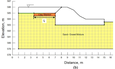
Figure 6. Modeling of the suggested (a) cutoff wall and (b) clay blanket
3.2 Clay blanket
A layer of compacted clay is suggested to be placed on the upstream ground surface. The suggested clay blanket, with 0.5 thickness, was assumed to have three values of the length (L) of 2, 4, and 6 m, as shown in Figure 6b. Based on the design report of the dam, the hydraulic conductivity of the clay soil that was used to construct the clay core was 1x10⁻⁷ m/sec. This value was used for the numerical model of the clay blanket which is less than the hydraulic conductivity of the foundation soil. Therefore, clay layer will decrease the quantity of seepage and exit gradient of the flow through the foundation.
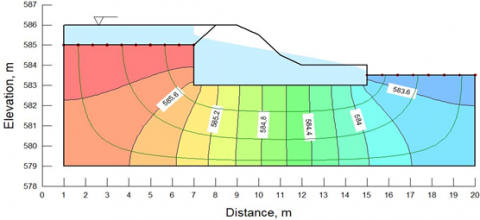
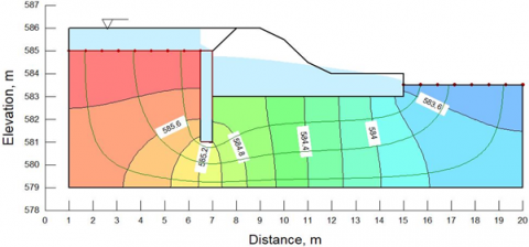
The results of the numerical model were used to facilitate safe and cost-effective treatment method of the seepage problem of H2 Dam. SEEP/W model was used to analyze the seepage at the operation water level of the reservoir with a study state condition. The flow lines and pore water pressure distribution in the foundation are shown in Figure 7. For the spillway models that were provided with cutoff wall and clay blanket, the typical results of the models are presented in Figure 8 and Figure 9, respectively.
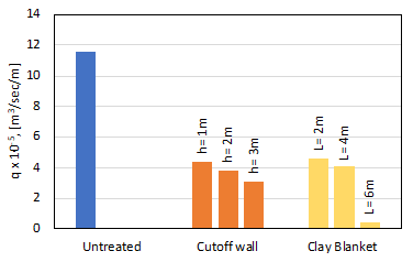
For the spillway models, the quantity of seepage, exit gradient, and the values of the safety factor against piping, as calculated from Eq. (1), are presented in Table 2. These values are also represented graphically in Figures 10 and 11. Based on the calculated values of seepage, the total quantity of seepage thorough the untreated foundation was estimated by 1503 m3/day. Unfortunately, no actual measurements are available for the seepage quantity to validate the results of the model. However, the seepage quantity was estimated from the observations of the drawdown in the reservoir water level as the depth of the daily drawdown was multiplied by the surface area of the reservoir to find the daily volume of seepage. The estimated value was 1307 m3/day which is 13% less than the calculated value indicating a good agreement between the two values. According to the study [21], a value of factor of safety from 3 to 4 is adequate to prevent piping. Therefore, the soil is considered unsafe against piping, as the calculated factor of safety of the untreated foundation was less than 3.
The seepage analysis was repeated after providing a cutoff wall and a clay blanket. As the cutoff wall of 3 m was used, the quantity of seepage decreased by 73% and the factor of safety against piping increased by 100 %. Likewise, the clay blanket was used the quantity of seepage decreased by 96% and the factor of safety increased by 110%. Based on the obtained results, the dam is clearly malfunctioning as the seepage underneath the spillway can dissipate the stored water and lead to uncontrolled seepage. The proposed methods of treatment can provide sufficient protection against excessive seepage and piping. The cost of each proposed method was not precisely estimated in this study. However, based on the available data of the dam location and the materials availability, a rough estimation of the cost indicated that the cost of the clay blanket was about 22% less than the cost of the cutoff wall. Therefore, tenement with a clay blanket will be more suitable to be applied for this case.
Figure 7. The flow net of the seepage through the untreated foundation
Figure 8. The flow net of the seepage with a cutoff wall
Figure 9. The flow net of the seepage with a clay blanket
Table 2. Seepage values obtained from the numerical models
|
Case |
q [m3/day/m] |
iexit |
FS |
|
Untreated Foundation |
11.6×10⁻⁵ |
0.56 |
1.8 |
|
Cutoff (h=1m) |
4.41×10⁻⁵ |
0.36 |
2.8 |
|
Cutoff (h=2m) |
3.86×10⁻⁵ |
0.32 |
3.1 |
|
Cutoff (h=3m) |
3.12×10⁻⁵ |
0.28 |
3.6 |
|
Clay Blanket (L=2m) |
4.62×10⁻⁵ |
0.39 |
2.6 |
|
Clay Blanket (L=4m) |
4.17×10⁻⁵ |
0.35 |
2.9 |
|
Clay Blanket (L=6m) |
0.42×10⁻⁵ |
0.26 |
3.8 |
Figure 10. The effect of the method of treatment on the quantity of seepage
Figure 11. The effect of the method of treatment on the factor of safety against piping
A numerical analysis was performed to evaluate the seepage problem underneath the spillway of Horan 2 Dam and to evaluate the treatment with a cutoff wall and a clay banket. The values of the quantity of seepage and the factor of safety against piping were determined from the developed numerical models, and the following conclusions are drawn from the analysis:
(1) Horan 2 Dam is considered misfunctioned dam because of the excessive seepage through the foundation of the spillway that have led to great losses in water storage.
(2) The observations indicated that the foundation of the spillway was unsafe against piping, as the calculated factor of safety was less than 3.
(3) Using a cut off wall with depths of 2, 4, and 6 m decreased the quantity of seepage up to 73% and increased the factor of safety against piping up to 100%.
(4) As a clay blanket with 2 to 6 m length was used, the quantity of seepage decreased up to 96% and the factor of safety against piping increased up to 110%.
(5) The treatment with a 6 m of clay blanket is recommended, as clay is a locally available that will make this option a cost-effective method comparing to using a cutoff wall.
(6) Small dams should be provided with monitoring instrumentations to measure piezometric levels of the reservoir and seepage discharges.
(7) The results of this study proved that the finite elements model was capable of simulating the leakage problem of H2 Dam, as the calculated values of seepage quantity were in agreement with the values that were estimated based on the field observations.
[1] Cedergren, H.R. (1997). Seepage, Drainage, and Flow Nets, 3rd Edition. Wiley.
[2] Foster, M., Fell, R., Spannagle, M. (2000). The statistics of embankment dam failures and accidents. Canadian Geotechnical Journal, 37(5): 1000-1024. http://dx.doi.org/10.1139/t00-030.
[3] Fell, R., Wan, C.F., Cyganiewicz, J., Foster, M. (2003). Time for development of internal erosion and piping in embankment dams. Journal of Geotechnical and Geoenvironmental Engineering, 129(4): 307-314. http://dx.doi.org/10.1061/(ASCE)1090-0241(2003)129:4(307)
[4] Malkawi, A.I.H., Al-Sheriadeh, M. (2000). Evaluation and rehabilitation of dam seepage problems. A case study: Kafrein dam. Engineering Geology, 56(3-4): 335-345. http://dx.doi.org/10.1016/S0013-7952(99)00117-9
[5] Ghobadi, M.H., Khanlari, G.R., Djalaly, H. (2005). Seepage problems in the right abutment of the Shahid Abbaspour dam, southern Iran. Engineering Geology, 82(2): 119-126. http://dx.doi.org/10.1016/S0013-7952(99)00117-9
[6] Wan, C.F., Fell, R. (2004). Investigation of rate of erosion of soils in embankment dams. Journal of Geotechnical and Geoenvironmental Engineering, 130(4): 373-380. http://dx.doi.org/10.1061/(ASCE)1090-0241(2004)130:4(373)
[7] Wang, E., Zhong, J., Zhao, Y., Mao, W. (2015). Analysis of seepage and seepage control measures in the rock masses of the Huilong pumped-storage power station. Bulletin of Engineering Geology and the Environment, 74(4): 1453-1462. http://dx.doi.org/10.1007/s10064-014-0702-9
[8] Uromeihy, A., Barzegari, G. (2007). Evaluation and treatment of seepage problems at Chapar-Abad Dam, Iran. Engineering Geology, 91(2-4): 219-228. http://dx.doi.org/10.1016/j.enggeo.2007.01.012
[9] Turkmen, S. (2003). Treatment of the seepage problems at the Kalecik Dam (Turkey). Engineering Geology, 68(3-4): 159-169. http://dx.doi.org/10.1016/S0013-7952(02)00225-9
[10] Moharrami, A., Moradi, G., Bonab, M.H., Katebi, J., Moharrami, G. (2015). Performance of cutoff walls under hydraulic structures against uplift pressure and piping phenomenon. Geotechnical and Geological Engineering, 33(1): 95-103. http://dx.doi.org/10.1007/s10706-014-9827-7
[11] Mansuri, B., Salmasi, F., Oghati, B. (2014). Effect of location and angle of cutoff wall on uplift pressure in diversion dam. Geotechnical and Geological Engineering, 32(5): 1165-1173. https://doi.org/10.1007/s10706-014-9774-3
[12] Sakhmarsi, A.A., Akhbari, H., Purya Naeimi, S., Kiapey, A. (2014). The effect of the cutoff wall conditions on the seepage characteristics of homogeneous earth-fill dams using SEEP/W. WALIA Journal, 30(S2): 176-182.
[13] Chouireb, M., AbdelkaderDjehiche. (2019). Simulation of seepage flow through an earthen dam with vertical drain and comparison of results with observations data (case study: Harreza dam-Algeria). Arabian Journal of Geosciences, 12(13). https://doi.org/10.1007/s12517-019-4542-6
[14] Chen, H. (2016). Analysis of numerical simulation of wading landslide in three gorges reservoir area based on outang landslide. Mathematical Modelling of Engineering Problems, 3(2): 71-74. https://doi.org/10.18280/mmep.030205
[15] Mohammed, A.K., Irzooki, R.H., Jamel, A.A., Mohammed-Ali, W.S., Abbas, S.S. (2021). Novel approach to computing critical and normal depth in circular channels. Mathematical Modelling of Engineering Problems, 8(6): 923-927. https://doi.org/10.18280/mmep.080611
[16] Sulaiman, S.O., Kamel, A.H., Sayl, K.N., Alfadhel, M.Y. (2019). Water resources management and sustainability over the Western desert of Iraq. Environmental Earth Sciences, 78(16): 1-15. http://dx.doi.org/10.1007/s12665-019-8510-y
[17] MWR. (2004). Design Report of Horan 2 Dam. Ministry of Water Resources, Baghdad, Iraq.
[18] Abdulkareem, A.H., Eyada, S.O., Mahmood, N.S. (2021). Improvement of a subgrade soil by using EarthZyme and cement kiln dust waste. Archives of Civil Engineering, 67(2). http://dx.doi.org/10.24425/ace.2021.137183
[19] Zomorodian, S.M.A., Moghispoor, S., O’Kelly, B.C., Babaei, S.S. (2020). Improving erosion resistance of silty sand using additives. Dams and Reservoirs, 30(1): 29-41. http://dx.doi.org/10.1680/jdare.20.00007
[20] Ezekwesili, O.J.I., Agunwamba, J.C. (2021). Mechanistic mathematical modelling of pothole development from loss of roadway subsurface-materials. Mathematical Modelling of Engineering Problems, 8(2): 170-178. https://doi.org/10.18280/ 080202
[21] Harza, L.F. (1935). Uplift and seepage under dams on sand. Transactions of the ASCE, 100(1): 1352-1385. https://doi.org/10.1061/TACEAT.0004