Dhafer A. Hamzah | Khaled Al-Farhany*
© 2022 IIETA. This article is published by IIETA and is licensed under the CC BY 4.0 license (http://creativecommons.org/licenses/by/4.0/).
OPEN ACCESS
The influence of the helical grooved path in the pipe was studied in the fully developed region of the pipe in this study. In fact, the applicable depth and pitch ratios minimize the cost and the production time of the manufacturing process. The Finite Volume Method (FNM) has been used with RNG k-ε turbulent model in this study. Heat and fluid flow in a pipe with a diameter of 0.25 m and a length of 5 m have been simulated. The improvement area starts after 3 meters, which represents to fully developed region, as examined and confirmed. The results showed that the efficiency improved by 5.8% compared to the plain pipe.
fully developed, turbulent flow, helical grooved, numerical, secondary flow
The researchers in engineering analysis focus on three primary goals, i.e. to increase performance, reduce costs, and, last but not the least, preserve the environment. Because striking a balance between all of these objectives is challenging, so, studies seek out compromises solutions Kumar et al. [1]. Researchers have made several attempts at using passive and active approaches to improve heat transmission and hydraulic performance Hamzah and Al-Farhany [2]. Some researchers combine passive methods with high demands for heat transfer enhancement. Ajeel et al. [3] used different shapes of channels and nanofluid with different concentrations. The study includes experimental and numerical methods to evaluate the high performance in turbulent Reynolds number and constant heat flux. They demonstrated that the trapezoidal-shaped channel with 2% silica nanofluid has the best thermal performance when pumping power is taken into account. Several academics are attempting to improve corrugated pipes by utilizing novel structures to quantify heat transfer in pipe flow [4-9]. Jin et al. [10] demonstrated a contemporary helically corrugated pipe with a six-start at the inlet of pipe. The research focuses on the impact of the six-start pitch and depth on the thermal performance of turbulent flow at constant wall temperature. The numerical findings show that when the pitch is increased, the secondary flow decreases progressively at Reynolds = 20,000, and the secondary flow distribution is low in the middle of the pipe and high at the flow's boundary. In the field of renewable energy to improve the absorber performance, Biswakarma et al. [11] concluded that for v grooved pipe at different values of constant heat flux and turbulent Reynolds number between 4000-6000, the heat transfer coefficient increases by 13.8% with an increase in pressure drop by 14.5%. The study used numerical technique and k-ε RNG turbulent model. Also, the validation of grid independence is presented in this work at elements of 16×105. Hong et al. [12] offer a new design as a wavy corrugated tube for generating eddies with varied corrugated numbers. They studied 19 cases of different corrugation amplitude, corrugation number, corrugation arrangement, and width with height. The boundary conditions were constant wall temperature at turbulent Reynolds number at range 7500 to 20,000. The essential point to remember is that the smooth pipe has a lower heat transmission rate compering with the modified pipe. The Nusselt number and friction factor increase as the corrugation number increases to 3 with parallel and counter arrangements.
The researcher aims to optimize his work after simulation and this is obvious in the study of Promthaisong et al. [13], whose study focuses on the perfect structure in a helical oval tube with a varied layout. With these setups, a wide variety of depth and pitch parameters were investigated at constant heat fluxes of 600 W/m2 and Reynolds numbers of 5000-20,000. The results showed that the maximum thermal performance of 1.3 verified at depth and pitch ratios of 0.05 and 0.6 respectively and also the sequence axes and orderly spaced helical oval pipe seem to give a good performance. Qian et al. [14] treated with fully turbulent conditions to create correlations for six start helically finned tubes. The high Reynolds number from 10,000 to 60,000 and conjugate heat transfer in shell side demonstrate in this study. They found that Nusselt number increase and friction resistance decrease as Reynolds number increasing, while the pitch increasing the above behavior decreasing for both parameters at a constant flow. In addition, the investigation detects the impact of increasing depth, which results in a random change in Nusselt number and an increase in flow resistance. An obvious effort was achieved by Moradi and Floryan [15] in correlations formulation for longitudinal grooves in pipes which are used to damp the turbulent drag. The study found that it can have the same flow rate for smooth and grooved pipe if applied the geometric correction factor correlation in the vicinity of the grooved wall. Promthaisong et al. [16] used the finite volume method to simulate forced convection heat transfer and hydrodynamic distribution in the spiral semicircle grooved tube. To show the secondary flow impact at Reynolds numbers ranging from 5000 to 20,000, different findings such as Nusselt number, flow structure, temperature profile, and friction factor ratio were obtained. At a Reynolds number of 5000, the study achieves the optimum values of the depth and the pitch ratios which are 0.06 and 1.4, respectively. Fadhil Smaisim [17] studied the influence of the Prandtl number on the severity index for corrugated pipe with four starts and Reynolds numbers ranging from 300 to 1500. The study reported that the optimal structure index was 4.6 × 10⁻² with heat transfer increment of 33.24% at Reynold number equal to 500.
According to the previous researches, combining certain passive techniques along with the domain without labeling the enhanced location effect, application problems, and cost of fabrication. The present work using the above techniques takes into consideration the study of semi-circle helically grooved in the fully developed region only. A pipe with a diameter of 0.25 m and a length of 5 m was simulated to model heat and fluid flow. After 3 meters, which corresponds to a totally developed area, the improvement area begins. The paper is organized as follow: Section 2, the working domain and applying conditions, Section 3, the grid equipment and its independency, and Section 4, Reynolds transport equations including the governing equations and parameters. Section 5 contains the results and discussion, and Section 6 has the conclusions.
In enhancement heat transfer cases, the modification in geometry as an example must be possible and appropriate. The possibility may be not complicated in manufacturing or modulating [18], while the appropriacy involves the weaker region of thermal performance. In this work, the semi-circle groove will be not a long pipe but at the end of the entry, region to re-create the disturbance mode. Figure 1 shows the configuration and dimensions of the geometry.
Figure 1. The modification of fully developed region and the entrance for modulation pipe
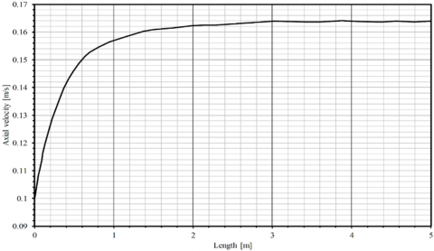
The cold inlet flows normally from the smooth side at 295 K and 2500 Reynolds, while the outlet flow at atmospheric pressure. The heating boundary conditions at the outer wall are constant wall temperature at 333 K. The fully developed region is determined by Figure 2 for the plain pipe, which indicates that when the velocity at the axial direction will be constant, the entry region will end according to Al-Nassri and Unny [19]. From the figure, the velocity development in the smooth five-meter pipe reaches the maximum velocity at an approximation of 3 m length. so, the improvement will be at the start of length 3m from the pipe. This scheme almost matches with empirical correlations for 25 mm of diameter in Ref. [20].
For laminar flow
$L_{h}=0.05 \times R e \times D$ (1)
For turbulent flow
$L_{h}=0.05 \times \operatorname{Re} \times \operatorname{Pr} \times D$ (2)
Figure 2. Velocity development a long pipe flow
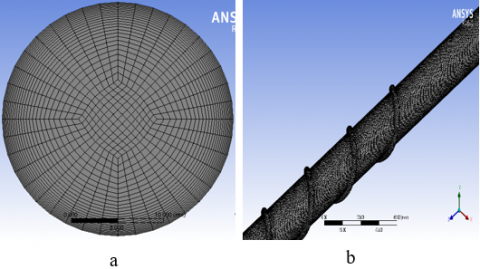
Figure 3. Grid generation: (a) plain pipe, (b) grooved pipe
Figure 4. Mesh validation development
The grid must achieve the required convergence for numerical equations through high refinement but not at the expense of time and cost. According to Ref. [16], the grid must have the following features: 1-The tetrahedral mesh is selected for the computational domain of the spirally semicircle-grooved tube. 2-At the near wall region, grids have high density based on the gradients of temperature, pressure, and velocity, which the first near-wall cell next to the wall which is determined by the Reynolds number and satisfies y+≈1. Figure 3(a) shows meshing for smooth pipe, which represents a simple case for heating flow in a pipe. In contrast in Figure 3(b) represents a complicated helically grooved pipe case, part of it grooved in a fully developed region. The methods, sizing, refinement, face meshing, and inflation all these techniques are used for best mesh results. The grid independence shows in Figure 4. gives the appropriate mesh for verified the average outlet temperature. The number of cells is near 25 × 106 with a minimum cell size of 0.1 mm.
For steady-state, incompressible flow the transformation to disturbance flow will be solved by RNG k-ε turbulent model. Conservation of mass, momentum, and energy equation applied according to Launder and Spalding [21] as follows:
$\frac{\partial \rho}{\partial t}+\vec{\nabla} \cdot(\rho \vec{V})=0$ (3)
$\frac{\partial(\rho \varepsilon)}{\partial t}+\frac{\partial}{\partial X_{j}}\left(\rho U_{j} \varepsilon\right)=$$\frac{\partial}{\partial X_{j}}\left[\left(\mu+\frac{\mu_{t}}{\sigma_{\epsilon R N G}}\right) \frac{\partial \varepsilon}{\partial X_{j}}\right]+\frac{\varepsilon}{k}\left(C_{\varepsilon 1 R N G} P_{k}-C_{\varepsilon 2 R N G} \rho \varepsilon+C_{\varepsilon 1 R N G} P_{\varepsilon \mathrm{b}}\right)$ (4)
while the divergence of a vector form for energy equation;
$\frac{\partial\left(\rho h_{t o t}\right)}{\partial t}-\frac{\partial p}{\partial t}+\nabla \cdot\left(U h_{t o t}\right)=\nabla \cdot(\lambda \nabla T)+\nabla \cdot(U \cdot \tau)+U \cdot S_{M}+S_{E}$ (5)
5.1 Hydrodynamic results
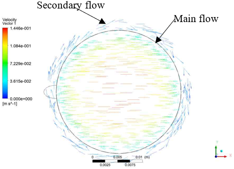
Figure 5. Flow development by grooved path
For any thermal performance enhancement, the hydraulic performance must be considered to evaluate the whole picture for the model. Hydraulic performance is concerned with pressure drop (Δp). Using a depth ratio of 0.1, a forced path for the flow is created, as illustrated in Figure 5. While the primary flow occupies up the largest space, the swirl secondary flow will form in the helical groove. The dominant swirl flow increases with increasing depth of the grooved path [22].
(a)
(b)
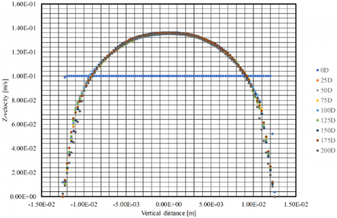
Figure 6. (a) Velocity profile at different streamwise for plain pipe; (b) Velocity profile at different streamwise for grooved pipe
The effect of the grooved path will be evident by the velocity profile for plain and grooved pipe as shown in Figure 6. The velocity profile in the plain pipe takes almost a parabolic shape and maintains a uniform flow at a far region from the wall, also the fully developed verified due to the low Reynold number. While for grooved pipe the transformation into turbulent flow leads to logarithm profile or according to the power law.
5.2 Thermal results
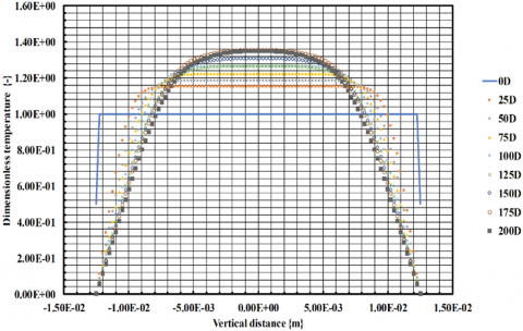
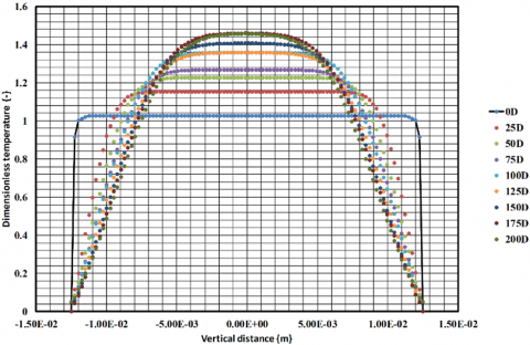
The heat flow distribution is described by comparison between plain and grooved pipes respectively as shown in Figure 7. The difference between stream-wise velocity and temperature in the fully developed regions is not the same, due to the helical grooved, whereas the disturbances will be created, and developed a new profile for the near-wall distance. The effect of grooved pipe with normal depth ratio is clear for modification of heat transfer by the dimensionless temperature at different streamwise positions. The range distributed for plain pipe is between 1.16-1.36, while for grooved pipe ranged between 1.18-1.44. This increment beyond to secondary and main swirl flow is generated by the spirally grooved path.
(a)
(b)
Figure 7. (a) Dimensionless temperature at different streamwise for plain pipe; (b) Dimensionless temperature at different streamwise for grooved pipe
(a)
(b)
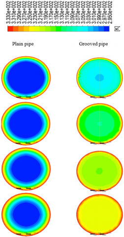
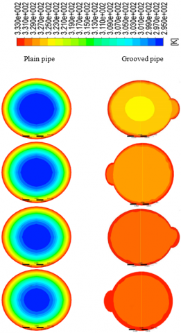
Figure 8. (a) Temperature contour development a long pipe at different positions from top to bottom (25D, 50D, 75D, and 100D); (b) Temperature contour development a long pipe at different positions from top to bottom (125D, 150D, 175D, and 200D)
More clear visualization is shown in Figure 8, which represents temperature contour development at different streamwise for the plain and grooved pipe. The effect of swirl flow due to grooved path is significant by mixing flow generated by secondary and main flow. More disturbance leads to generate fluctuation velocities in all directions for merge flow between core flow and wall flow.
In this study, the effect of the helical grooved path in the pipe was investigated numerically in the fully developed region of the pipe. The obtained results led to highlight the conclusions listed below.
[1] Kumar, A., Singh, S., Chamoli, S., Kumar, M. (2019). Experimental investigation on thermo-hydraulic performance of heat exchanger tube with solid and perforated circular disk along with twisted tape insert. Heat Transfer Engineering, 40(8): 616-626. https://doi.org/10.1080/01457632.2018.1436618
[2] Hamzah, D.A., Al-Farhany, K. (2019). Effect of twisted tape ratio on the solar generator half-length pipe. International Journal of Heat and Technology, 37(2): 407-412. https://doi.org/10.18280/ijht.370205
[3] Ajeel, R.K., Saiful-Islam, W., Sopian, K., Yusoff, M.Z. (2020). Analysis of thermal-hydraulic performance and flow structures of nanofluids across various corrugated channels: An experimental and numerical study. Thermal Science and Engineering Progress, 19: 100604. https://doi.org/10.1016/j.tsep.2020.100604
[4] Han, S.W., Woo, Y.Y., Lee, T., Kim, J., Jeong, J.H., Moon, Y.H. (2021). Manufacturing of a corrugated double-layered tube for the high-performance compact heat exchanger. The International Journal of Advanced Manufacturing Technology, 112(7): 2065-2080. https://doi.org/10.1007/s00170-020-06419-y
[5] Al-Obaidi, A.R., Alhamid, J. (2021). Investigation of thermo-hydraulics flow and augmentation of heat transfer in the circular pipe by combined using corrugated tube with dimples and fitted with varying tape insert configurations, International Journal of Heat and Technology, 39(2): 365-374. https://doi.org/10.18280/ijht.390205
[6] Wu, Z., Qiu, L., Wu, C., Zhou, D. (2021). Study on flow and heat performance of thermal-hydrolyzed sludge in a double-pipe heat exchanger with a series of inner corrugated tubes. International Journal of Thermal Sciences, 170: 107160. https://doi.org/10.1016/j.ijthermalsci.2021.107160
[7] Al-Obaidi, A.R., Alhamid, J. (2021). Investigation of flow pattern, thermohydraulic performance and heat transfer improvement in 3D corrugated circular pipe under varying structure configuration parameters with development different correlations. International Communications in Heat and Mass Transfer, 126: 105394. https://doi.org/10.1016/j.icheatmasstransfer.2021.105394
[8] Rehman, Mazhar, A., Liu, S., Shukla, A. (2021). Numerical investigation of the heat transfer enhancement using corrugated pipes in a PCM for grey water harnessing. Thermal Science and Engineering Progress, 23: 100909. https://doi.org/10.1016/j.tsep.2021.100909
[9] Qin, S.Y., Xiao, H., Xiao, Y., Liu, P., Zhou, F.Y., Liu, W., Liu, Z.C., Shan, F. (2020). Experimental investigation of the coherent structures in a spirally corrugated pipe. International Journal of Heat and Fluid Flow, 84: 108601. https://doi.org/10.1016/j.ijheatfluidflow.2020.108601.
[10] Jin, Z.J., Chen, F.Q., Gao, Z.X., Gao, X.F., Qian, J.Y. (2017). Effects of pitch and corrugation depth on heat transfer characteristics in six-start spirally corrugated tube. International Journal of Heat and Mass Transfer, 108: 1011-1025. https://doi.org/10.1016/j.ijheatmasstransfer.2016.12.091
[11] Biswakarma, S., Roy, S., Das, B., Kumar Debnath, B. (2020). Performance analysis of internally helically v-grooved absorber tubes using nanofluid. Thermal Science and Engineering Progress, 18: 100538. https://doi.org/10.1016/j.tsep.2020.100538.
[12] Hong, Y., Du, J., Wang, S., Huang, S.M. (2017). Heat transfer and flow behaviors of a wavy corrugated tube. Applied Thermal Engineering. 126: 151-166. https://doi.org/10.1016/j.applthermaleng.2017.07.135.
[13] Promthaisong, P., Jedsadaratanachai, W., Eiamsa-ard, S. (2018). Numerical simulation and optimization of enhanced heat transfer in helical oval tubes: Effect of helical oval tube modification, pitch ratio, and depth ratio. Heat Transfer Engineering. 39(19): 1665-1685. https://doi.org/10.1080/01457632.2017.1384281
[14] Qian, J.Y., Chen, M.R., Wu, Z., Liu, X.L., Jin, Z.J., Sundén, B. (2018). A geometric study on shell side heat transfer and flow resistance of a six-start spirally corrugated tube. Numerical Heat Transfer, Part A: Applications, 73(8): 565-582. https://doi.org/10.1080/10407782.2018.1459381
[15] Moradi, H.V., Floryan, J.M. (2017). Laminar flow in grooved pipes. AIAA Journal, 55(5): 1749-1752. https://doi.org/10.2514/1.J055718
[16] Promthaisong, P., Boonloi, A., Jedsadaratanachai, W. (2016). Numerical investigation on turbulent forced convection and heat transfer characteristic in spirally semicircle-grooved tube. International Journal of Mechanical and Materials Engineering, 11(1): 9. https://doi.org/10.1186/s40712-016-0062-2
[17] Fadhil Smaisim, G. (2018). Augmentation of heat transfer in corrugated tube using four-start spiral wall. Al-Qadisiyah Journal for Engineering Sciences, 10(4): 451-467. https://doi.org/10.30772/qjes.v10i4.493
[18] Maradiya, C., Vadher, J., Agarwal, R. (2018). The heat transfer enhancement techniques and their Thermal Performance Factor. Beni-Suef University Journal of Basic and Applied Sciences, 7(1): 1-21. https://doi.org/10.1016/j.bjbas.2017.10.001
[19] Al-Nassri, S.A., Unny, T. (1981). Developing laminar flow in the inlet length of a smooth pipe. Applied Scientific Research, 36(5): 313-332. https://doi.org/10.1007/BF00411891
[20] Chen, B., Qin, F.G.F., Shao, Y., Xiao, H., Huang, S., Ho, K.J.E.S.W.C. (2018). The Development of Swirling Decaying Laminar Flow in an Annular Pipe. E3S Web of Conferences, 51: 03001. https://doi.org/10.1051/e3sconf/20185103001
[21] Launder, B.E., Spalding, D.B. (1974). The numerical computation of turbulent flows. Computer Methods in Applied Mechanics and Engineering, 3(2): 269-289. https://doi.org/10.1016/0045-7825(74)90029-2
[22] Liu, J., Xie, G., Simon, T. W. (2015). Turbulent flow and heat transfer enhancement in rectangular channels with novel cylindrical grooves International Journal of Heat and Mass Transfer, 81: 563-577. https://doi.org/10.1016/j.ijheatmasstransfer.2014.10.021