Konkala Balashowry*![]() | M.V.R. Durga Prasad
| M.V.R. Durga Prasad![]() | V. Rathinam
| V. Rathinam![]() | Bapurao G. Marlapalle
| Bapurao G. Marlapalle![]() | Sachin P. Komble
| Sachin P. Komble![]() | Jagannath S. Gawande
| Jagannath S. Gawande![]() | Baban K. Suryatal
| Baban K. Suryatal![]() | Shravan H. Gawande
| Shravan H. Gawande![]()
© 2024 The authors. This article is published by IIETA and is licensed under the CC BY 4.0 license (http://creativecommons.org/licenses/by/4.0/).
OPEN ACCESS
This research focused on reducing emissions from petrol engines to mitigate greenhouse gases. Experiments aimed to decrease pollutants from petrol engines and enhance efficiency at full load using hydrogen as a secondary fuel, injecting it for 2 milliseconds and 2.5 milliseconds. The study comprised two phases: one using petrol alone at all loads, and the other combining petrol with hydrogen injections at 216 gm/hour and 270 gm/hour. Performance, pollutants, brake, and mechanical efficiencies were compared between phases. Efficiency gradually improved with load for the 2ms injection. Efficiency improved in all timing cases with hydrogen compared to running on petrol alone. The highest efficiencies occurred with 2.5ms hydrogen injection, reducing pollutants at full load, making it the optimal interval. Injecting hydrogen in petrol engines improves efficiency by reducing emissions. Injecting hydrogen at 270 gm/hour at full load increased brake and indicated thermal efficiency by 9%, with no change in mechanical efficiency compared to pure petrol, which was slightly higher. Emissions of NO, CO2, and HC were reduced by 16.5%, 15%, and 17.2% respectively. Oxygen percentage by volume increased by 10.43%, supporting complete combustion.
petrol engine, hydrogen, alternative fuel, performance characteristics, pollutants, mechanical efficiency, brake thermal efficiency, data storage system
The energy demand is increasing day by day with the increase of the world population. Due to this, it not only reduces current energy reserves but also increases energy losses. Due to the determinate potential of oil reserves, it is necessary to increase the use of alternative fuels. The use of hydrogen in combination with petroleum-derived fuels in internal combustion engines can reduce harmful exhaust emissions from fossil fuels. Therefore, researchers continue to work for an economic and safe fuel that does not harm the environment.
Ravi et al. [1] modified single-cylinder compression ignition engine to work as lean burn spark ignition engines that run on LPG and substitute hydrogen for oxygen. Different compression ratios were used for keeping the speed constant and observed that for high compression ratios the emissions were found less when combined with hydrogen with a compression ratio 10.5:1 as optimal. The brake thermal power and brake thermal efficiency were increased. At lower loads the thermal efficiency was reduced. By adding hydrogen, the combustion rate was enhanced. The emissions of carbon monoxide, carbon dioxide and NO were reduced considerably. Jain et al. [2] assessed the effect of split fuel addition and EGR on PCCI combustion, the study tested different start of main injection and pilot injection timings as well as EGR rates. The findings suggest that the best injection timing and EGR rate combinations can optimize PCCI combustion. Patil et al. [3] conducted a test using oxy hydrogen (HHO) in a spark ignition engine to understand the performance. HHO gas was generated by the electrolysis of water with KOH solution as the catalyst and allowed it to mix with a fresh stream of air before the inlet of the carburetor. The generation of gas was controlled by varying supply of current. The Author observed that HHO can be easily integrated with spark ignition engine. Author has controlled the flow of HHO with 9Amps current throughout the experiment. It was observed that the engine performance was improved with on the introduction of HHO gas. It was found that there was an increase in brake thermal efficiency by 10.82% and the brake specific fuel consumption was decreased by 9.74%. As the volumetric efficiency is concerned a 3% decrement was observed. Su et al. [4] explored the effect of spark timing on the efficiency of a dual-fuel H₂-gasoline rotary engine. To conduct experiment a rotary engine was set up with port fuel injection along with an electronic management module to control fuel injection, excess air ratio and hydrogen volume fraction. The engine was operated at 4500 rpm and with an absolute pressure of 35kPa. The author observed that for a specified volumetric percentage peak cycle pressure, the chamber temperature was increased the brake thermal efficiency was increased initially and then decreased when advancement took in spark. The emissions of NO and HC are reduced after retarding the spark. Yan et al. [5] researched on hydrogen enriched natural gas (HCNG) in spark ignition engines as hydrogen has shorter ignition delay, minimum ignition energy and higher laminar speed which enhances the complete combustion and leads to higher thermal efficiency and low NO emissions. Mixing of hydrogen with transport fuels such as gasoline, biogas, diesel and alcohols improved in cylinder combustion with minimum emissions. Abhijna et al. [6] generated gas from electrolysis of water and used in the bike as a fuel with the mixture of air and petrol to understand the viability in terms of performance and emissions. It is observed that there was an increase in fuel efficiency of 5 to 10% by reducing pollutants. Vinoth and Paturu [7] provided an overview of current advancements in the research of hydrogen-powered internal combustion engines. Advances in direct hydrogen injection, in-cylinder heat transfer, modeling, and combustion techniques at both the engine and vehicle levels are included in the overview. These research efforts led to excellent efficiency and emissions that are well within regulatory limitations, as well as satisfactory specific power outputs. Mourad and Mahmoud [8] performed experiments on four-stroke petrol engines using blends of propanol and gasoline up to 15% under various load conditions. Authors observed that the propanol added to petrol had improved the fuel economy by 2.84% for a blend ratio 15%, and there was a reduction in pollutants hydrocarbons and carbon monoxide 14.18% and 10.87% respectively. Mahendran et al. [9] evaluated various assumptions regarding the structure and content of HHO gas, explore the laws of combustion and chemical processes of electrolytic reactions, and suggested design and implementation factors to enhance the gas production percentage and introduced engine systems that uses HHO gas. System complexity, safety, expense, and electrolysis efficiency are cited as the primary hurdles in employing HHO gas in engines. By using HHO engine torque, power and thermal efficiency have been increased by reducing NO, CO and HC. Ismaila et al. [10] focused on unburned hydrocarbons which are the major pollutants in the form of exhaust gases. Brown gas which is a mixture of hydrogen and oxygen was used as a new source of energy for complete combustion of the mixture and used dry cell of HHO because its advantages such as compact and easy to install in engines. HHO gas is produced from water and which will be ionized by NaOH as an electrolyte. Finally, it is observed that there was a reduction of fuel consumption by 17% reduction in CO, 27% reduction in HC, 15% increase in O2 and 1% increase in CO2. Nadaleti and Przybyla [11] explored the possible use of rice industrial waste, which includes husk and effluent, to generate biogas and syngas with a high hydrogen concentration. These gasses or their combinations can be used to fuel SI, taking benefit of the rice industry's potential of bioenergy. The study conducted engine testing with common biogas and syngas compositions and discovered that increasing the surplus ratio (l) value from 1 to 1.25 reduces carbon monoxide and NOx pollutants while boosting the stated efficiency. Yu et al. [12] investigated three possible injection modes as petrol, petrol plus homogenous hydrogen, and petrol plus stratified hydrogen. The results demonstrated that adding hydrogen raised NOx emissions, while reducing CO and HC pollutants and boosting brake thermal efficiency, since the combustion temperature is higher. The stratified hydrogen mode with petrol improved brake thermal efficiency, flame expansion duration, fast combustion duration, and COV over the homogeneous hydrogen mode. Increased in NOx and CO due to denser concentrations of hydrogen near the ignition switch and leaner concentrations near the wall were also observed. Akal et al. [13] worked on hydrogen as an alternative fuel for the forthcoming generations by keeping in mind the requirement of energy which is pollution free. The Author conducted experiments on petrol, liquefied petroleum gas and diesel. When hydrogen was added to petrol and liquefied petroleum gas and diesel the torque and power were increased in petrol engines, whereas decreased in liquefied petroleum and diesel engines. As the emission part is concerned in petrol and LPG are decreased, whereas in diesel engines NO levels are increased. Przybyła and Nadaleti [14] conducted experiments using low calorific value gas in a spark ignition engine. This low calorific value gas is simulated by the mixture of carbon monoxide, hydrogen and nitrogen. The Author conducted experiment on single cylinder GX270 honda engine. Engine operation was controlled by a microprocessor controller and was constant speed of 3000 rpm. No impact on internal parameters was observed, if the duration of inert gas increased led to increase in NO emissions and reduced HC, CO emissions. Lhuillier et al. [15] worked experimentally on combustion and emissions of a spark ignition engine with premixed ammonia and hydrogen. Ammonia gas blends in different ranges have been mixed with hydrogen and tests were conducted. It is observed that 20% by volume of hydrogen improved the stability of combustion by avoiding misfires along with good indicated efficiency. Krishna et al. [16] focused on an alternative fuel to reduce emissions led to global warming in which hydroxy gas produced by electrolysis was used as an alternative fuel to deplete hydrocarbon emissions in a variable compression gasoline engine. The compression ratios varying from 7 to 10 show a decrement in fuel consumption and improved brake thermal efficiency. The calorific value of the fuel has been increased by adding hydroxy gas. Emissions such as CO, O2 and unburnt gases are decreased with slight an increase in NO emissions because of the high temperature in the combustion chamber. Masuk et al. [17] addressed various fuel usages in petrol engines and compared brake thermal efficiency, brake specific fuel consumption, compression ratio and torque and toxic emissions. Every fuel has their own individual benefits using different fuels like hydrogen, natural gas, propane and bio-gas. It is observed that hydrogen and propane can run at higher compression ratio than petrol fuel as the octane number is more for hydrogen. Bharath et al. [18] worked on methanol-gasoline mix on engine efficiency and emissions, both with and without additions. Methanol-gasoline blend fuels have been shown increased engine performance and lower pollution. Low alcohol concentrations can lead to problems like corrosion, phase separation, and increased fuel use. Stepien [19] examined the most recent findings on the use of H₂ as a fuel in ICEs, compiled the knowledge and viewpoints of international research institutions on the scientific feasibility of using H₂ in ICEs, and offers a summary of the benefits and drawbacks of using H₂ as a solution. The study analyzes the unique physical, chemical, and functional features of H₂ for IC engines and offers a critical evaluation of H₂ combustion approaches, concentrating on the difficulties and potential related to port and direct hydrogen injection technology. It is seen that hydrogen is suitable as an alternative energy source to improve the performance and greatly to reduce emissions. Salek et al. [20] worked on the hydrogen/gasoline dual-fueled engine would be affected by water injection and changes to the start of combustion. Utilizing the AVL BOOST programme, the engine is simulated and tested against experimental data. Genetic algorithm (GA) and multiobjective optimization was used to find the best water injection and start of combustion values for different H₂ energy shares. The findings demonstrate that the suggested solution increases the mean effective pressure and effectiveness of the brake, with an increase in engine equivalent brake specific fuel consumption of up to 4.61% without any pollutants. Zang et al. [21] observed that the cost of hydrogen is the biggest influence based on the FT fuel's lowest retail price. By 2050, the manufacturing of FT fuel could be cost-effective compared to pretax petroleum diesel pricing at a cost of $0.8/kg for H₂. The report also said, that enhancing H₂ and CO₂ recycling contributions should be the main goal of future system optimization. Du et al. [22] reviewed different versions of current standards concerning H2 for fuel cell vehicles in China and abroad furthermore, the causes and developing trends are analyzed for the changes in these standards in detail. On the other hand, according to characteristics of H2 for fuel cell vehicles, standard H2 purification technologies, such as pressure swing adsorption (PSA), membrane separation and metal hydride separation, were analyzed, and the latest research progress was reviewed. Fan et al. [23] addressed the energy needs, nations like Japan, Korea, and China are actively creating hydrogen infrastructure. PEMFCs, which are economically feasible for automotive applications, are the main topic of the article. The discussion focuses on automotive applications while covering all essential PEMFC components, temperature and water control, and associated characterization approaches.
Due to the depletion of conventional fuels, different researchers worked on alternative ways to improve the fuel resources. Research shows exhaustive performed work on diesel and petrol engines with diverse combination of fuels like LPG along with petrol and diesel. Some of the researcher added hydrogen with petrol with constant compression ratios and also obtained variation in the compression ratios. Some of the researchers worked with split type injection with exhaust gas recirculation with PCCI and also by using HHO, propane, stratified hydrogen to improve performance on enhanced combustion process. Based on the literature review, in this work experiment are performed by injecting hydrogen in two phases with varied quantities to improve the performance with reduced pollutants.
The experimental process is classified as the first step includes the conduction of trials using petrol as a fuel in the first phase, then conduction of trials using petrol and hydrogen as a fuel in the second phase, in third step obtained results are compared for both and combined fuels and last data analysis and interpretation was performed. This experiment is generalizable. Applicable to other engines too. In the first phase the experiment was conducted using petrol only as fuel. In the second phase without decreasing the fuel flow, additionally hydrogen is added 216 gm/hour and 270 gm/hour at 2 and 2.5 milliseconds respectively for reducing the pollutants as a main component and to increase indicated power.
2.1 Test engine
The PFI (Port Fuel Injection) kit system is designed to inject a variety of fuels like hydrogen, CNG, LPG, and alcohol fuel. This system can be used in both SI and CI engines as a dual-fuel mode operation. The manifold/port injection of different fuels can be switched by following a set of procedural steps. The PFI system can be operated with an Open ECU for liquid and gas systems. In diesel mode, the PFI liquid and gas can be used as a dual fuel mode operation. The system provides various engine characteristics like pressure, exhaust gas recirculation injection time, and variable compression ratio, all within safe operating limits. The PFI liquid and gas can be safely operated with a delivery pressure up to 50-60 PSI and 70 PSI, respectively. The Open ECU controls the total process. Necessary instrumentation is provided for the system with the help of engine-soft software (Figure 1).
Figure 1. Engine test bed
2.2 Specifications
Table 1 presents the specifications of all parameters of the used engine.
2.3 Fuel injection system
The multi fuel port injector system is a type of fuel injection system that is designed to work with different types of fuels. It uses a set of injectors that are designed to deliver the appropriate amount of fuel for each fuel type, ensuring that the engine receives the correct amount of fuel. The multi fuel port injector system is beneficial in areas where different types of fuels are available or cost-effective and can help reduce emissions and improve fuel efficiency. However, it is more complex and expensive than traditional fuel injection systems and requires additional maintenance to ensure proper system functioning. The weight of hydrogen injection can be calculated by {(Diesel flow rate) x (calorific value of diesel)} / (calorific value of hydrogen).
2.4 Data storage system (Engine soft software)
In this experiment software called Engine Soft where the entire data will be stored when the engine is in running condition. With the same software the amount of hydrogen will be controlled and that could be loaded manually with respect to time, if hydrogen is to be stopped, we can feed in the system zero. As accuracy part is concerned all parameters are directly stored in system and there won’t be any deviation.
Table 1. Parameters specifications
|
Parameters |
Specifications |
|
Engine type |
Single cylinder, 4 stroke, with variable speed. (computerized). |
|
Diameter of the cylinder |
87.50 mm |
|
Stroke |
110.00 mm |
|
Speed |
1800 rpm |
|
Power |
4.50 kW |
|
Number of Cylinders |
1 |
|
Number of Strokes |
4 |
|
Cooling System |
Water cooled |
|
Con Rod Length |
234.00 mm |
|
Compression Ratio (CR) |
10 |
|
Working volume |
661.45 cc |
|
Specific Gas Constant |
1 kJ/kg-K |
|
Density of air |
1.17 kg/m3 |
|
Diameter of orifice |
20 mm |
|
Cd of orifice |
0.60 |
|
Dynamometer Type |
Eddy current dynamometer |
|
Fuel Density |
740 kg/m3 |
|
Calorific Value |
44000 kJ/kg |
2.5 Measurement of air/fuel/temperature/pressure
Airflow measurement in an engine is typically accomplished using a U-tube manometer that is connected to an air box equipped with an orifice. The diameter of the orifice is usually around 20 mm, which allows for accurate measurement of airflow. Fuel measurement, on the other hand, involves using a fuel flow meter that is placed in the fuel line between the fuel tank and the engine. This device measures the volume of fuel passing through the line, which is used by the engine control unit (ECU) to optimize engine performance by adjusting the fuel injection timing. To measure the temperature in an engine, thermocouples are used that have a range from 0 to 1200°C. The readings from the thermocouples are typically transmitted through a 4-20 mA current loop, and the device is powered by a 24 V DC power supply. Pressure measurement is also critical for optimal engine performance and is accomplished using pressure sensors that are typically placed in the combustion chamber, intake manifold, and exhaust system.
2.6 Emission measurement
2.6.1 Exhaust gas analyzer
DIGAS exhaust gas analyzer (444 AVL) is employed for measuring pollution constituents. The concentration of pollutants such as NOX, CO2, CO and soot are measured by continuous online monitoring for all the trails of experiments. A non-dispersive infrared sensor has been used for the measurement of CO and CO2 and a photochemical sensor has been used for NOX measurement. AVL DIGAS exhaust gas analyzer used in this research work is shown in Figure 2. The details of specifications are shown in Table 2.
Figure 2. Digas exhaust gas analyzer
Table 2. Specifications of Digas exhaust gas analyzer
|
Description |
Measurement Range |
Accuracy |
|
CO % volume |
0-10 |
0.01 |
|
CO2 % volume |
0-20 |
0.1 |
|
HC ppm |
0-20000 |
1 |
|
O2 % volume |
0.22 |
0.01 |
|
NOx ppm |
0-5000 |
1 |
Portable exhaust gas analyzers typically measure the concentration of various gasses in the exhaust, like CO, CO2, oxygen, nitrogen oxides, and hydrocarbons. Some models may also measure particulate matter or other pollutants. To use a portable exhaust gas analyzer, the device is typically attached to the tailpipe of the engine being tested. The engine is then run under various conditions, such as at idle, under load, or at different speeds, while the analyzer measures the emissions. The results are displayed on a screen or printed out for analysis.
2.6.2 Smoke meter
The smoke measuring instrument consists of a pump which sucks a definite quantity of exhustr smoke through a white filter paper.The reflectivity of the white paper is measured with standard Bosch smoke meter which consists of high source photo detector. Before conducting the experiment the tube and pump are completely made free from smoke which occurs from the previous measurement, as shown in Figure 3 and Table 3.
Figure 3. AVL smoke meter
Table 3. AVL smoke meter
|
Description |
Measurement Range |
Accuracy |
|
Opacity |
0-100 |
± 1% of full scale |
|
Heating time |
5min |
- |
|
Power supply |
12v |
- |
|
Display |
digital |
- |
Figure 4 shows the indicated brake and frictional power at different speeds. At 1150 rpm the brake power, frictional power and indicated power were noted as 3.02, 3, and 3.05kW respectively. The frictional power slowly increased from 1150 rpm and reached to a maximum at 1620 rpm with a value of 3.3kW and suddenly decrement started at 1620 rpm and slowly decreased to 3.25 at 1800 rpm. The indicated power at 1150 rpm was observed as 3.06kW and gradually increased to 1620 rpm with a maximum value of 7.5kW and further also increased till 1800 rpm with a further maximum value7.6kW. Brake power was increased from 1150 rpm to 1400 rpm and further increased to 1620 rpm to 4.1kW and further too increased to 4.3kW at 1800 rpm. At maximum speed the brake power and indicated power have shown similar values because at higher rpm the power developed gets increased.
Figure 4. Variation of IP, BP, FP with speed for petrol engine
Figure 4 shows on X axis speed and on Y axis indicated, brake and frictional power. In this particular software three parameters comes directly on Y axis.
Before commencing the experiment, we have changed the gaskets and piston rings of the engine and we added the hydrogen in addition to the normal fuel which is being taken inside the engine the hence the compression ratio gets increased more over clean and complete combustion might have taken place. Hence there might be an increment in indicated power and indicated mean effective pressure.
At the lower rpm the indicated, the frictional mean effective pressures are low. As the speed increases the gradual increment in pressure and reaches to a maximum of 8.474bar and 3.74bar respectively, at 1610 rpm and a pressure fall was observed afterword.
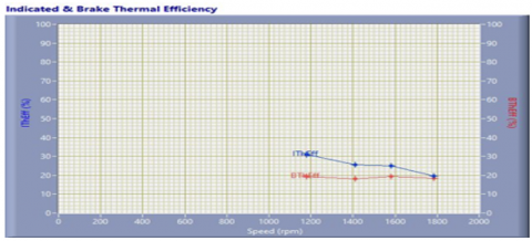
From Figure 5 it is observed that the brake mean effective pressure was more at the lower speed and later a great reduction was observed at high speed (1800rpm) due to increased friction. It is observed that the friction at rated power was significantly higher than at peak torque speed. From Figure 6 full load condition, the brake thermal and indicated thermal efficiency are found to be 30.4% and 28.4%, respectively. The brake thermal efficiency decreases as the speed of the engine increases. This may be due to the increase in mechanical friction. These two curves are quite reverse to each other. From Figure 7 at full load with respect to speed condition, torque, mechanical efficiency and volumetric efficiency are found as 25.8N-m, 63% and 59%. As the speed increases, the torque and volumetric efficiency decrease at full load. The mechanical efficiency decreases rapidly up to 1600 rpm from 1100 rpm and increases gradually to 57.2% until it reaches minimum load. The decrement of mechanical efficiency at higher rpm is due to the losses of eddy current.
Figure 5. Variation of IMEP, BMEP, FMEP with speed
Figure 6. Variation of Indicated, and brake thermal efficiency speed
Figure 7. Variation of torque, mechanical & volumetric efficiencies with speed
From Table 4, at full load NO and soot were observed lesser as compared to other loading conditions. NO was found to be 890 ppm and soot was observed 0.2 ppm. Carbon monoxide was observed higher when compared to other loads. The reason for the increase in CO and CO2 is due to the almost complete combustion in the combustion chamber. Hydrocarbons are slightly higher compared to 75% of the load because of some particles which are unburnt.
Table 4. Emissions of petrol engine at different loads
|
Speed |
CO % Volume |
HC ppm |
CO2 % Volume |
O2 % Volume |
NO ppm |
Soot (S in ppm) |
|
1200 |
0.05 |
58 |
6.30 |
12.08 |
890 |
0.2 |
|
1400 |
0.04 |
61 |
6.90 |
11.40 |
1031 |
0.6 |
|
1600 |
0.03 |
53 |
7.10 |
11.17 |
1030 |
0.2 |
|
1800 |
0.02 |
31 |
3.80 |
15.73 |
573 |
0.00 |
3.1 Hydrogen injection along with petrol for 216 gm/hour
From hydrogen cylinder look up table connects system which converts valve into values. The time for seconds we can set manually in the system according the hydrogen cylinder opens and closes. If we don’t want, we need to keep these values as zero. Additional cost incurring parameters are hydrogen cylinder with look up table system and hydrogen gas. From Figure 8, it is observed that the brake power is varying linearly from zero to full load. When only petrol is used as fuel and the similar is the case when hydrogen was injected at a rate of 216 gm/hour, then the brake power increased from 3.1kW to 3.3kW. The increased power was due to the injection of hydrogen in the combustion process as compared to petrol injection only as a fuel.
Figure 8. Variation of IP, BP, FP with speed for petrol + H₂ at 2ms
From Figure 9, the brake mean effective pressure increases linearly from zero load to 1/3 (one third) initially and reached to 5 bars at full load and this value was slightly increased approximately 20% compared to petrol as fuel. From Figure 8 the brake thermal efficiency was increased from 30.4% to 35% with the addition of hydrogen as the mass of the fuel kept constant. There was an increment of 15.1% in brake thermal efficiency and this may be due to the intake charge of petrol along with hydrogen.
From Figure 10, at 1725 rpm if we consider the BMEP value is 4.58bars, IMEP value is 9 bars and FMEP is 4.4 bars at 25% load. At full load that is at 1200 rpm the BMEP is 4.99bars, IMEP is 6.6bars and FMEP is 1.6 bars. At any given speed the values of BMEP, IMEP and FMEP are satisfying the power calculations.
Figure 9. Variation of IMEP, BMEP, and FMEP speed for petrol+ H₂ at 216 gm/hour
Figure 10. Variation of Indicated and brake thermal efficiency with speed for petrol+ H₂ at 2ms
From Figure 11, it is observed that the torque values increased from 25.8 to 26.3 N-m at full load. The mechanical efficiency was increased from 63% to 75%. Similarly, the volumetric efficiency was also increased from 62.3% to 82.5% at full load condition. The improvement in all parameters was due to better fuel combustion, when hydrogen was injected which makes the engine more responsive and faster which in turn increases the engine horse power and leads to directly improve all three parameters. Table 5 presents the emissions for petrol + hydrogen 216gm/hour.
Figure 11. Variation of torque, mechanical efficiency and volumetric efficiency with speed for petrol+ H₂ at 216 grams per hour
Table 5. Emissions for petrol + hydrogen 216gm/hour
|
Speed |
CO % Volume |
HC ppm |
CO2 % Volume |
O2 % Volume |
NO ppm |
Soot (S) ppm |
|
1200 |
0.06 |
60 |
6.90 |
11.27 |
976 |
0.2 |
|
1400 |
0.04 |
47 |
7.10 |
11.12 |
1039 |
1.3 |
|
1600 |
0.04 |
57 |
7.20 |
11.30 |
1030 |
0.2 |
|
1800 |
0.04 |
62 |
6.00 |
12.63 |
840 |
0.00 |
3.2 Petrol + H₂ at 270 gm/hour
From Figure 12, at full load condition, the brake power, the indicated and frictional power was observed as 3.3kW, 5.2kW, and 2kW, respectively when the hydrogen was injected at a rate of 270 gm/hour. From Figure 13, BMEP, IMEP and FMEP were found 5bars, 8 bars and 3bars respectively. Compared to 216 gm/hour injection there was increment in indicated and brake power by 15.5% and 6.16% respectively when injection of hydrogen at a rate of 270 gm/hour. The improvement in the combustion process with the help of hydrogen led to the increment in power.
Figure 12. Variation of IP, BP, and FP with speed
Figure 13. Variation of IMEP, BMEP, and FMEP with speed
Figure 14. Variation of indicated and brake thermal efficiency with speed
Figure 15. Variation of torque, mechanical efficiency and volumetric efficiency with speed
Table 6. Emissions for petrol + hydrogen 270 gm/hour
|
Speed |
CO % Volume |
HC ppm |
CO2 % Volume |
O2 % Volume |
NO ppm |
Soot (S in ppm) |
|
1200 |
0.06 |
60 |
6.90 |
11.27 |
976 |
0.2 |
|
1400 |
0.04 |
47 |
7.10 |
11.12 |
1039 |
1.3 |
|
1600 |
0.04 |
57 |
7.20 |
11.30 |
1030 |
0.2 |
|
1800 |
0.04 |
62 |
6.00 |
12.63 |
840 |
0.00 |
Thermal efficiency is input heat energy and mechanical efficiency is output of the engine which will be lesser than thermal energy as losses is involved in it.
From Figure 13, at full load condition the indicated mean effective pressure was increased by 19% compared to 216 gm/hour hydrogen injection. It was observed that there was no change in brake mean effective pressure. From Figure 14, at full load condition the indicated thermal efficiency was increased by 16.2% comparatively to 216 gm of hydrogen injection. Similarly, there was a small increment in the brake thermal efficiency of 4.1% to in this case. It is observed that, both the efficiencies were increased in this case. Table 6 presents the emissions for petrol + hydrogen 270 gm/hour. From the Figure 15, at full load the torque was increased by 6.4% comparatively and there was decrement of mechanical efficiency by 15%, whereas the volumetric efficiency was good for the pure petrol only.
As global warming is a burning issue we tried with hydrogen as a partial and alternative fuel as petroleum products are getting depleted and observed what the impacts in combustion chamber. We understand there was an increment towards clean combustion from the results of the pollutants emitted. The experiment was conducted in two stages, in the first stage the experiment was conducted with petrol and in the second stage hydrogen was injected through the ports for 216 and 270 grams per hour, respectively. The gasoline engine was run at full load, the brake average effective pressure was observed as 4.37 bars and indicated mean effective pressure was observed as 7.67 bars. The brake thermal, indicated thermal and mechanical efficiency were found as 16.86%, 29.57 and 57% respectively. The emissions emitted at full load condition were found as 0.02% by volume of CO, 3.8% CO2 by volume and 15.73% oxygen was observed. The hydrocarbons were observed as 31 ppm and NO was found 573 ppm.
The experiment found that at 216 grams per hour of hydrogen injection, with the engine at full load, the brake mean effective pressure was observed as 4.58bars, the indicated pressure was is 8.98bar, and brake thermal efficiency is 17.50%, indicated thermal efficiency is 34.29%, and the mechanical efficiency is 51.04%. The emission content for hydrogen injection at 216 grams per hour was 0.04% volume of CO, 62 ppm of HC, 6.00%volume of CO2, 12.63% volume of O2 and 840 ppm of NO.
The experiment found that at 270 grams per hour of hydrogen injection, with the engine at full load, BMEP is 4.55bar, IMEP is 4.91bar, brake thermal efficiency is 18.34%, indicating thermal efficiency is 19.78% and mechanical efficiency is 92.71%. The emission content for hydrogen injections at 2.5ms are 0.06% volume of CO, 45 ppm of HC, 7.50% volume of CO2, 10.35% volume of O2, and 1000 ppm of NO. The highest efficiency was observed when hydrogen was injected at 2.5ms, which is the optimum time interval for hydrogen injection. As the volume of hydrogen increases the Brake Thermal Efficiency is increased by reducing the emissions and pollutant.
Research is completed with respect to the hydrogen injection taken in to consideration for this particular experiment. It could be further extended with increment in hydrogen quantity prior to knock attains.
[1] Ravi, K., Bhasker, J.P., Porpatham, E. (2017). Effect of compression ratio and hydrogen addition on part throttle performance of a LPG fuelled lean burn spark ignition engine. Fuel, 205: 71-79. https://doi.org/10.1016/j.fuel.2017.05.062
[2] Jain, A., Singh, A.P., Agarwal, A.K. (2017). Effect of split fuel injection and EGR on NOx and PM emission reduction in a low temperature combustion (LTC) mode diesel engine. Energy, 122: 249-264. https://doi.org/10.1016/j.energy.2017.01.050
[3] Patil, N.N., Chavan, C.B., More, A.S., Baskar, P. (2017). Generation of oxy-hydrogen gas and its effect on performance of spark ignition engine. In IOP Conference Series: Materials Science and Engineering, 263(6): 062036. https://doi.org/10.1088/1757-899X/263/6/062036
[4] Su, T., Ji, C., Wang, S., Shi, L., Yang, J., Cong, X. (2017). Effect of spark timing on performance of a hydrogen-gasoline rotary engine. Energy Conversion and Management, 148: 120-127. https://doi.org/10.1016/j.enconman.2017.05.064
[5] Yan, F., Xu, L., Wang, Y. (2018). Application of hydrogen enriched natural gas in spark ignition IC engines: From fundamental fuel properties to engine performances and emissions. Renewable and Sustainable Energy Reviews, 82: 1457-1488. https://doi.org/10.1016/j.rser.2017.05.227
[6] Abhijna, B., Lokesh, P., Mahesh, D., Chandrashekar, S., Gopinath, R. (2018). Hydrogen powered petrol engine. International Journal of Scientific & Engineering Research, 9(7): 138-141.
[7] Vinoth K.I., Paturu, P. (2020). A study of hydrogen as an alternative fuel. International Journal of Ambient Energy, 41(12): 1433-1436. https://doi.org/10.1080/01430750.2018.1484803
[8] Mourad, M., Mahmoud, K.R. (2018). Performance investigation of passenger vehicle fueled by propanol/gasoline blend according to a city driving cycle. Energy, 149: 741-749. https://doi.org/10.1016/j.energy.2018.02.099
[9] Mahendran, M., Revanth, S., Kumar, M.S., Karthik, R.S. (2018). Review of performance and emission characteristics of HHO gas as a fuel. International Journal of Research in Engineering, Science and Management, 1(11): 420-423.
[10] Ismail, T.M., Ramzy, K., Abelwhab, M.N., Elnaghi, B.E., Abd El-Salam, M., Ismail, M.I. (2018). Performance of hybrid compression ignition engine using hydroxy (HHO) from dry cell. Energy Conversion and Management, 155: 287-300. https://doi.org/10.1016/j.enconman.2017.10.076
[11] Nadaleti, W.C., Przybyla, G. (2018). Emissions and performance of a spark-ignition gas engine generator operating with hydrogen-rich syngas, methane and biogas blends for application in southern Brazilian rice industries. Energy, 154: 38-51. https://doi.org/10.1016/j.energy.2018.04.046
[12] Yu, X., Li, G., Du, Y., Guo, Z., Shang, Z., He, F., Shen, Q.X., Li, D., Li, Y. (2019). A comparative study on effects of homogeneous or stratified hydrogen on combustion and emissions of a gasoline/hydrogen SI engine. International Journal of Hydrogen Energy, 44(47): 25974-25984. https://doi.org/10.1016/j.ijhydene.2019.08.029
[13] Akal, D., Öztuna, S., Büyükakın, M.K. (2020). A review of hydrogen usage in internal combustion engines (gasoline-Lpg-diesel) from combustion performance aspect. International Journal of Hydrogen Energy, 45(60): 35257-35268. https://doi.org/10.1016/j.ijhydene.2020.02.001
[14] Przybyła, G., Nadaleti, W. (2020). Pollutant emissions, performance and combustion behaviour assessment of an Si gas engine fuelled with Lcv gas containing carbon monoxide and hydrogen diluted by nitrogen. International Journal of Hydrogen Energy, 45(11): 7119-7127. https://doi.org/10.1016/j.ijhydene.2019.12.117
[15] Lhuillier, C., Brequigny, P., Contino, F., Mounaïm-Rousselle, C. (2020). Experimental study on ammonia/hydrogen/air combustion in spark ignition engine conditions. Fuel, 269: 117448. https://doi.org/10.1016/j.fuel.2020.117448
[16] Krishna, V.M., Reddy, A.H., Kumar, M.S., Raghu, A. (2020). Effect of hydroxy gas addition on performance and exhaust emissions in variable compression spark ignition engine. Materials Today: Proceedings, 24: 930-936. https://doi.org/10.1016/j.matpr.2020.04.404
[17] Masuk, N.I., Mostakim, K., Kanka, S.D. (2021). Performance and emission characteristic analysis of a gasoline engine utilizing different types of alternative fuels: A comprehensive review. Energy & Fuels, 35(6): 4644-4669. https://doi.org/10.1021/acs.energyfuels.0c04112
[18] Bharath, B.K., Arul Mozhi Selvan, V. (2021). Influence of higher alcohol additives in methanol–gasoline blends on the performance and emissions of an unmodified automotive SI engine: A review. Arabian Journal for Science and Engineering, 46(8): 7057-7085. https://doi.org/10.1007/s13369-021-05408-x
[19] Stępień, Z. (2021). A comprehensive overview of hydrogen-fueled internal combustion engines: Achievements and future challenges. Energies, 14(20): 6504. https://doi.org/10.3390/en14206504
[20] Salek, F., Babaie, M., Hosseini, S.V., Bég, O.A. (2021). Multi-objective optimization of the engine performance and emissions for a hydrogen/gasoline dual-fuel engine equipped with the port water injection system. International Journal of Hydrogen Energy, 46(17): 10535-10547. https://doi.org/10.1016/j.ijhydene.2020.12.139
[21] Zang, G., Sun, P., Elgowainy, A.A., Bafana, A., Wang, M. (2021). Performance and cost analysis of liquid fuel production from H2 and CO2 based on the Fischer-Tropsch process. Journal of CO2 Utilization, 46: 101459. https://doi.org/10.1016/j.jcou.2021.101459
[22] Du, Z., Liu, C., Zhai, J., Guo, X., Xiong, Y., Su, W., He, G. (2021). A review of hydrogen purification technologies for fuel cell vehicles. Catalysts, 11(3): 393. https://doi.org/10.3390/catal11030393
[23] Fan, L., Tu, Z., Chan, S.H. (2021). Recent development of hydrogen and fuel cell technologies: A review. Energy Reports, 7: 8421-8446. https://doi.org/10.1016/j.egyr.2021.08.003