Hussein Mohammed Ali![]() | Majid Khaleel Najem
| Majid Khaleel Najem![]() | Emad Toma Karash*
| Emad Toma Karash*![]() | Jamal Nayief Sultan
| Jamal Nayief Sultan![]()
© 2023 IIETA. This article is published by IIETA and is licensed under the CC BY 4.0 license (http://creativecommons.org/licenses/by/4.0/).
OPEN ACCESS
The main duty of engineers is to guarantee that structures are both erect and adhere to codes, which proves their outstanding functionality and economic viability. In today's elastic materials, the von Mises stress values have to be verified when examining fatigue or failure. In the domains of heavy lifting, robotics, mechanical and offshore engineering, oil and gas engineering, and civil engineering, the Von Mises criteria are among the most often used benchmarks for assessing productivity conditions. In this study, seven I-beams models will be built, the first model without holes and the other six models with holes in various shapes (square, triangular, circular, hexagonal, and rectangular). The ANSYS program will be used to solve it using the finite element method. For the upper surface of these models, equal loads will be applied. The findings demonstrate that the shear stress values for the seven models were less than the shear stress values of the metal, which came to (370MPa), in line with the theory of maximum shear stress. With a value of (62.7MPa), the second-best model was the best. One of the most important conclusions when comparing the values of von Mess stresses with the von Mess theory of stress is that the third model (with rectangular openings) performed better than the other models when compared to the first model because its value was the same in both models (370MPa). The seventh model (hexagonal holes) had the lowest maximum value of stress intensity at 261MPa, per the results. being aware that this model weighs (70Kg) less than the first.
strain, finite element method, displacement, cantilever beam, stress, deflection
Currently, cast steel beams are used extensively due to their many structural applications and serviceable performance due to the distinctive and significant properties they have, such as light weight, high strength, and the ability to withstand various weather conditions and temperatures. Along with other crucial qualities, it has rather modest economic costs. The fabrication of 'cellular' beams, which are lighter deeper sections, from structural sections. These sections are made by rewarding hot rolled steel sections that have been sliced into deeper beams with a sequence of circular holes. The pieces can be made into quite big holes through which services can travel, and they are structurally sound. Cellular girders are better suited for use in practical applications as long-span secondary beams than girders without slots because the shear capacity of a beam is frequently significantly reduced by slots. The openings where shear stresses are very high can be strengthened by filling them in or using horizontal stiffeners, allowing them to be created for use as primary members. Utilizing fabricated sections, a distinct design for cellular beams allows for the selection of the flange widths, web thickness, and depth to best match the applied loads and opening dimensions. Fabricated cellular beams are more effective for heavily loaded primary beams because the web thickness may be easily increased [1-3].
Numerous researchers have proposed various techniques in various studies to investigate the magnitude of stresses and deflections in curved beams under various loading situations [4-6]. While many research studies took into account bending and stretching simultaneously, for instance [7, 8]. Ghuku and Saha [9] in this article by merging the bending and stretching loading states, a curved beam with a geometric cutout in the shape of a circular hole was modeled for the primary LS. In the study [10], polished beams adopt a tapered shape and have circular openings on their surface. These openings have various diameters. The findings of this study indicate that the ideal diameters and opening spaces for each of the span lengths in order to achieve the lowest pressure and displacement are different. In the studies [11-14], beams were the subject, and cantilevering beams were created by giving the beam a tapered shape. Results from these studies show that the tapered shape is very ideal for cantilever beams because the internal bending and shearing force of the supports, which creates the specific load, is concentrated only in the region close to the support because the cantilever beam is fixed by only one support. In the study [15], a novel kind of cell bundle with sinusoidal apertures was investigated and contrasted with conventional circular apertures. Three beams with various opening sizes were chosen. In order to determine the final values of the force, this study first set out to identify the patterns that result in the failure of these beams. The experimental findings provided valuable qualitative and quantitative data that can be used to better understand and predict the behavior of the cellular bundles that contain the sinusoidal openings. The numerical model that was created and tested performed well in predicting the experiment's outcomes. Additionally, it may be used as a tool to produce complementary results in order to build an analytical model. Nowadays, cellular beams are used extensively in steel construction, and in actual field applications, they are the most widely used long-span system. Whereas this new variety of these cell bundles demonstrated a mechanical behavior with regard to bending resistance that is almost identical to that of openings with open rectangular shapes [16]. It is much harder to identify the critical regions surrounding circular openings than those that are rectangular or hexagonal, where it appears that the corners are the critical regions [17]. Numerous studies, in particular the study [18], presented significant findings through a study based on finite element technology, which was used to develop a new and ideal method for reliable design in order to confirm the capacity of these cell bundles with circular openings to withstand various stresses in addition to bending resistance. In the study [19], the influence of hole diameter with hole place on the lateral torsion behavior of cantilever beams was investigated. Imperforated sample and perforated sample were two different sets of samples used in this study. Based on the findings, it was determined that the diameter of the hole and its place have an impact on the lateral bending behavior, particularly for short beams. Seven different web opening shapes circle, square, pentagonal, and hexagonal were utilized in this article. using the finite element technique to build models [20]. The results demonstrate that displacements and different stresses are significantly influenced by the type and shape of openings on the surface of the sill. In the study [21], the ANSYS program was used to perform static and dynamic analyses of the cast steel beam section in order to compare the deflection, stress distribution, and shear stress. The outcomes under a consistent light load are significant.
Recent research has looked into the possibility of using FRP composites, such as CFRP sheets that are externally bonded pile, to strengthen RC beams with large longitudinal holes [22]. CFRP strips that are cemented to the surface area [23]. Many studies have compared the use of conventional and modern composite materials, which are used in many fields, including aviation, construction, industry, and other fields, in order to obtain an engineering structure that is distinguished by light weight and has the same resistance to stresses and strains that appear on it as a result of carrying different loads. These studies made mention of these subjects [24-30].
Seven Beams models will be created in the current work, the first model without holes and the other sixth models having holes of different shapes (square, triangular, circular, hexagonal, and rectangular). The ANSYS program will be used to solve it using the finite element technique. Along with the weight of the beam itself, a combined load of bending load and additional load in the form of torque will be imposed. The results will be compared to the displacements, stresses, and strains that occur in the five models, with the first model without holes, after loading. The models with holes all have the same weight, making it possible to select the model with the best efficiency among the five when compared to the first model without holes.
The following topics will be continued in the article: Models shapes and dimension, Materials selected, Results and discussion, Path results. Conclusions, Recommendations and future studies, and References.
The details of the beams that were created by using the ANSYS 15.0 program. The properties of the materials they are constructed of, and the shape of those models.
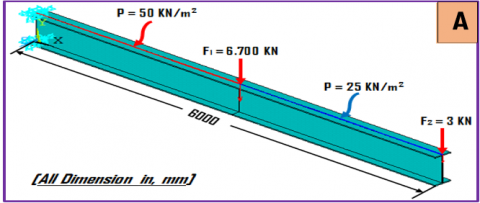
(1) The first model: A model without holes and made of steel, form (1-A).
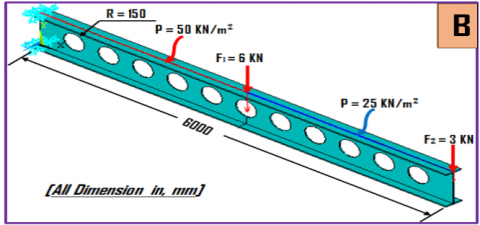
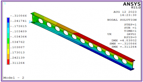
(2) The second model: A model with holes in the shape of a circular and made of steel, shaped (1-B).
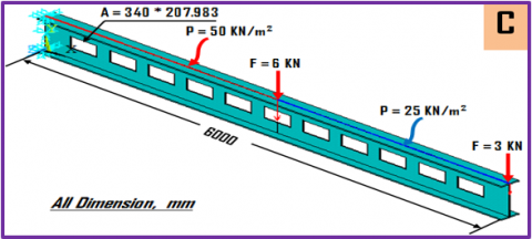
(3) The third model: A model with holes in the shape of a rectangle and made of steel, shaped (1-C).
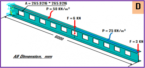
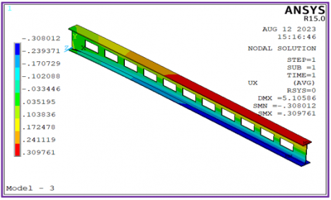
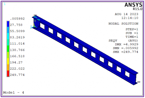
(4) The seventh model: A model with holes in the shape of a square and made of steel, shaped (1-D).
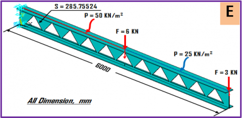
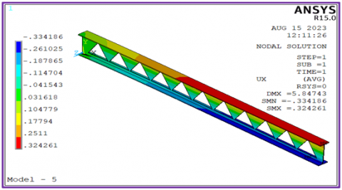
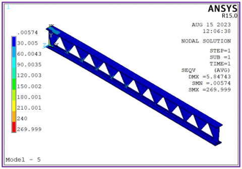
(5) The fifth model: A model with triangle holes made of steel, shaped like (1-E).
(6) The sixth model: A model with holes in the shape of a pentagonal and made of steel, shaped (1-F).
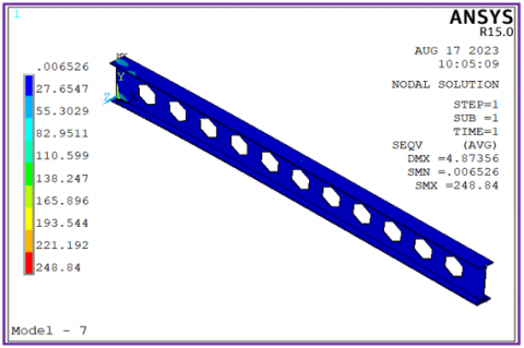
(7) The seventh model: A model with holes in the shape of a hexagon and made of steel, shaped (1-G).
Figure 1 shows the different loads that were applied, and they were equal in all models.
Figure 1. Show the models shapes, dimensions, and loads applied
The mechanical properties of steel (SM45C) listed in Table 1. The selection of this metal was based on its extensive applications in the building and construction industry, as well as in the manufacturing of machine parts, including bodies for cars and trucks, among other applications.
Table 1. Mechanical characteristics of the models [31-33]
|
Model |
Shapes of Holes |
Materials |
Density, $\rho$, (Kg/m3) |
Yield Strength, Sy MPa |
Shear Strength, Sy MPa |
Modulus of Elasticity, E, (GPa) |
Passion’s Ratio |
Modulus of Rigidity, G, (GPa) |
|
M-1 |
------- |
Steel (SM45C) |
7600 |
370 |
370 |
207 |
0.3 |
80 |
|
M-2 |
circle |
Steel (SM45C) |
7600 |
370 |
370 |
207 |
0.3 |
80 |
|
M-3 |
rectangle |
Steel (SM45C) |
7600 |
370 |
370 |
207 |
0.3 |
80 |
|
M-4 |
square |
Steel (SM45C) |
7600 |
370 |
370 |
207 |
0.3 |
80 |
|
M-5 |
triangle |
Steel (SM45C) |
7600 |
370 |
370 |
207 |
0.3 |
80 |
|
M-6 |
pentagon |
Steel (SM45C) |
7600 |
370 |
370 |
207 |
0.3 |
80 |
|
M-7 |
hexagon |
Steel (SM45C) |
7600 |
370 |
370 |
207 |
0.3 |
80 |
The results of loading the seven models with various loads Figure 1, and using the finite element method with the ANSYS 15.0 program are shown in Tables 2, 3 and Figures 2-8. It is possible to identify the locations of the maximum and minimum tensile and compressive stress values, as well as the tensile and compressive strains that developed on the seven models after loading them, by comparing the values of the results. Additionally, the maximum and minimum deflection values that appeared on the seven models after loading in the (x, y, and z) directions are visible.
Table 2. Results of tension side stresses and strains
|
Model |
Maximum Tension Deformations (mm) |
Maximum Stresses Tension (MPa) |
Maximum Strains Tension ($\mu \varepsilon$) |
||||||||||||||||||
|
$U_x$ |
$U_y$ |
$U_z$ |
$\sigma_{x}$ |
$\sigma_{y}$ |
$\sigma_{z}$ |
$\tau_{x y}$ |
$\tau_{yz}$ |
$\tau_{xz}$ |
$\sigma_{1}$ |
$\sigma_{2}$ |
$\sigma_{int.}$ |
$\sigma_{von}$ |
$\varepsilon_x$ |
$\varepsilon_y$ |
$\varepsilon_z$ |
$\varepsilon_{xy}$ |
$\varepsilon_{yz}$ |
$\varepsilon_{xz}$ |
$\varepsilon_{int.}$ |
$\varepsilon_{von}$ |
|
|
M-1 |
0.317 |
0.012 |
0.179 |
322 |
160 |
209 |
50.3 |
31.0 |
108 |
379 |
169 |
294 |
284 |
1022 |
401 |
681 |
631 |
389 |
1360 |
41.2 |
36.8 |
|
M-2 |
0.311 |
0.012 |
0.181 |
310 |
155 |
205 |
48.0 |
27.8 |
105 |
366 |
163 |
262 |
250 |
979 |
376 |
653 |
603 |
349 |
1321 |
46.6 |
48.1 |
|
M-3 |
0.310 |
0.012 |
0.161 |
310 |
155 |
204 |
49.9 |
27.0 |
106 |
366 |
163 |
264 |
252 |
982 |
517 |
667 |
627 |
339 |
1325 |
36.2 |
36.9 |
|
M-4 |
0.312 |
0.012 |
0.158 |
308 |
154 |
202 |
49.4 |
27.6 |
108 |
363 |
162 |
262 |
249 |
975 |
384 |
660 |
620 |
346 |
1357 |
43.4 |
43.6 |
|
M-5 |
0.324 |
0.015 |
0.178 |
321 |
182 |
216 |
53.4 |
27.8 |
117 |
380 |
170 |
282 |
270 |
1014 |
749 |
703 |
671 |
349 |
1472 |
41.3 |
81.6 |
|
M-6 |
0.314 |
0.013 |
0.178 |
316 |
157 |
217 |
45.0 |
27.8 |
106 |
372 |
167 |
285 |
269 |
1001 |
417 |
674 |
565 |
349 |
1334 |
42.7 |
42.8 |
|
M-7 |
0.313 |
0.012 |
0.162 |
307 |
153 |
202 |
48.8 |
27.6 |
107 |
363 |
162 |
261 |
249 |
974 |
372 |
663 |
613 |
346 |
1340 |
46.7 |
49.7 |
Table 3. Results of compression side stresses and strains
|
Model |
Maximum Compression Deformations, (mm) |
Maximum Stresses Compression (MPa) |
Maximum Strains Compression (µε) |
||||||||||||||||||
|
$U_x$ |
$U_y$ |
$U_z$ |
$\sigma_{x}$ |
$\sigma_{y}$ |
$\sigma_{z}$ |
$\tau_{x y}$ |
$\tau_{yz}$ |
$\tau_{xz}$ |
$\sigma_{1}$ |
$\sigma_{2}$ |
$\sigma_{int.}$ |
$\sigma_{von}$ |
$\varepsilon_x$ |
$\varepsilon_y$ |
$\varepsilon_z$ |
$\varepsilon_{xy}$ |
$\varepsilon_{yz}$ |
$\varepsilon_{xz}$ |
$\varepsilon_{int.}$ |
$\varepsilon_{von}$ |
|
|
M-1 |
0.316 |
4.780 |
0.137 |
408 |
186 |
211 |
66.0 |
40.2 |
124 |
162 |
186 |
0.01 |
0.01 |
1398 |
673 |
716 |
829 |
505 |
1560 |
410 |
370 |
|
M-2 |
0.311 |
4.829 |
0.133 |
331 |
152 |
187 |
62.7 |
39.1 |
121 |
144 |
151 |
0.01 |
0.01 |
1122 |
672 |
609 |
790 |
491 |
1526 |
460 |
480 |
|
M-3 |
0.308 |
5.097 |
0.150 |
307 |
144 |
190 |
63.5 |
39.7 |
122 |
124 |
149 |
0.01 |
0.01 |
1024 |
672 |
613 |
797 |
499 |
1528 |
360 |
370 |
|
M-4 |
0.310 |
4.983 |
0.159 |
262 |
143 |
182 |
63.1 |
39.3 |
121 |
120 |
131 |
0.01 |
0.01 |
876 |
673 |
568 |
792 |
494 |
1516 |
430 |
430 |
|
M-5 |
0.334 |
5.839 |
0.160 |
300 |
171 |
199 |
102 |
43.8 |
130 |
133 |
156 |
0.01 |
0.01 |
997 |
684 |
613 |
1285 |
550 |
1632 |
413 |
816 |
|
M-6 |
0.322 |
5.217 |
0.142 |
338 |
156 |
195 |
63.6 |
35.6 |
137 |
148 |
156 |
0.01 |
0.01 |
1139 |
672 |
614 |
799 |
447 |
1727 |
427 |
428 |
|
M-7 |
0.311 |
4.864 |
0.156 |
302 |
143 |
188 |
64.9 |
39.4 |
120 |
123 |
147 |
0.01 |
0.01 |
1021 |
672 |
582 |
816 |
494 |
1510 |
467 |
497 |
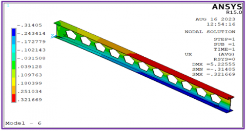
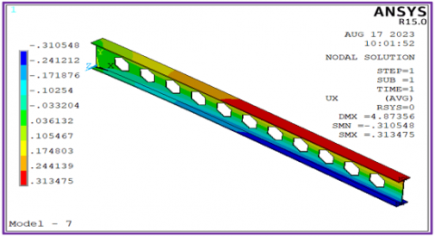
Figure 2. Results of the displacement in y-direction ($U_x$), for the seven models
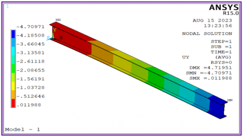
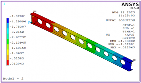
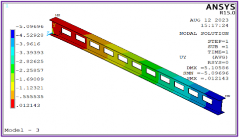
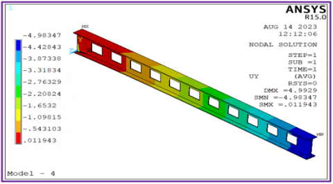
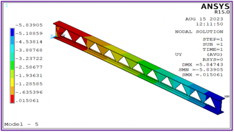
Figure 3. Results of the displacement in y-direction ($U_y$), for the seven models
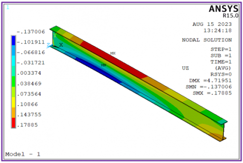
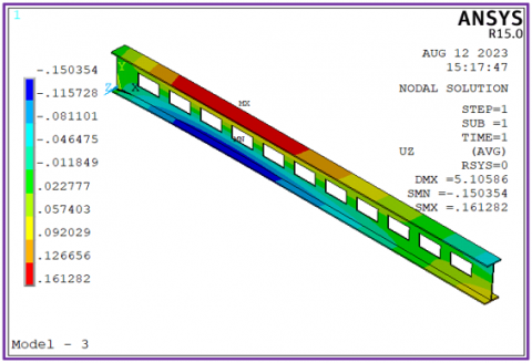
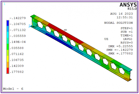
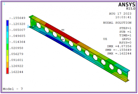
Figure 4. Results of the displacement in y-direction ($U_z$), for the seven models
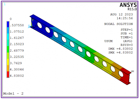
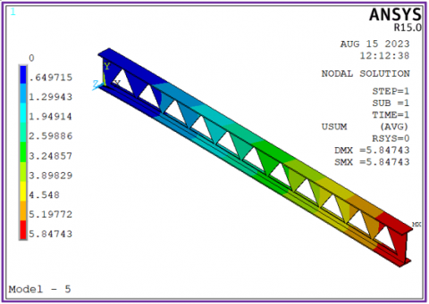
Figure 5. Results of the deflection ($\delta_{ {sum }}$), for the seven models
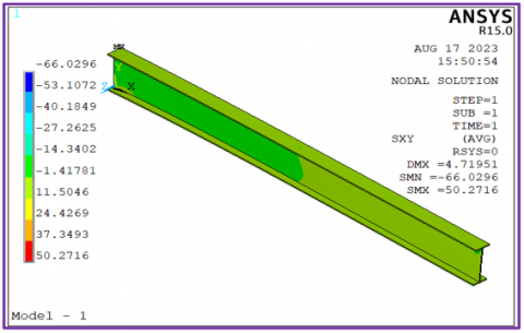
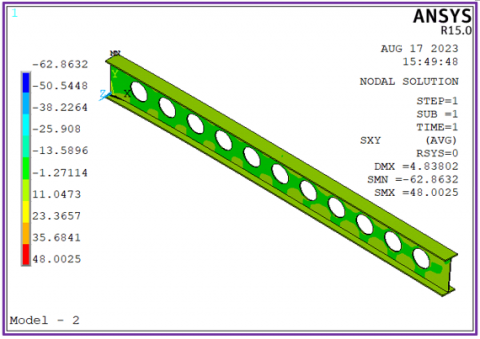
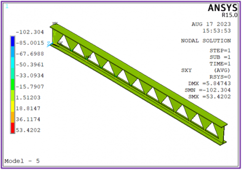
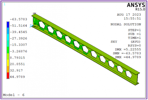
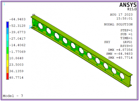
Figure 6. Results of the shear stress in $\left(\tau_{x y}\right)$, for the seven models
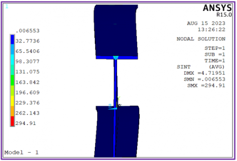
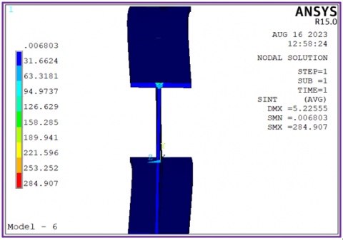
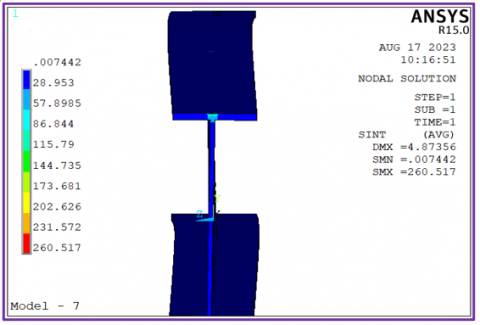
Figure 7. Results of the intensity stress in $\left(\sigma_{i n t.}\right)$, for the seven models
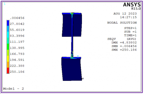
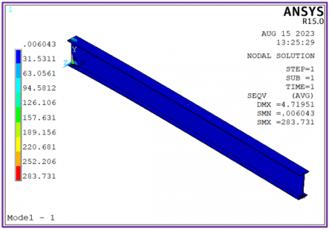
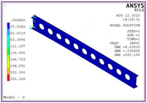
Figure 8. Results of the von mises stress in ($\sigma_{v o n.}$), for the seven models
Path Results
The chosen horizontal path (V-V) from the start of the model to its conclusion is shown in Figure 9. The selection of this path was made with the intention of comparing the displacement values and stresses that the seven models experience after being loaded with various loads.
Figures 10-15 show the various displacements and stresses brought on by applying various loads to each of the seven models along the path (V-V).
Figure 9. A line of the path (V-V)
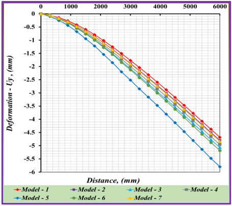
Figure 10. Deformation results ($U_y$) comparison for the seven models
Figure 11. Deformation results ($U_{ {sum }}$) comparison for the seven models
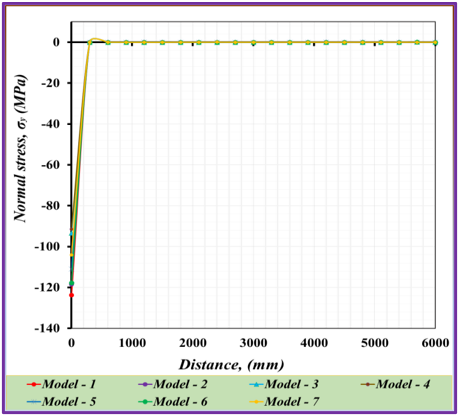
Figure 12. Normal stress results ($\delta_{y}$) comparison for the seven models
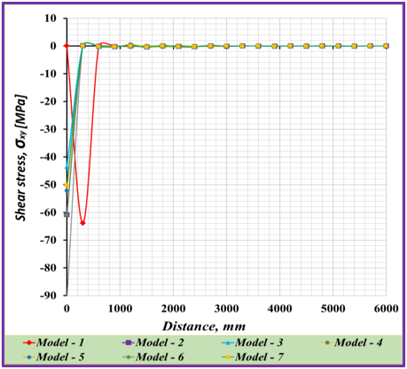
Figure 13. Normal stress results ($\tau_{x y}$) comparison for the seven models
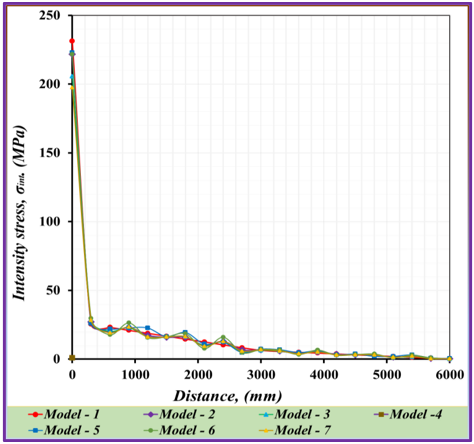
Figure 14. Normal stress results ($\delta_{int.}$) comparison for the seven models
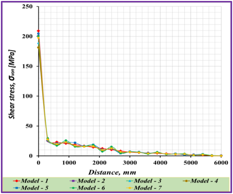
Figure 15. Von mises stress results ($\sigma_{v o n.}$) comparison for the seven models
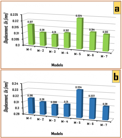
A comparison of the maximum tensile displacements towards the x-axis of the seven models is shown in Figure 16(a). The results of the tensile displacements ($U_x$) show that the fifth model had a greatest value, which was (0.324mm), and the third model had the lowest value, which was (0.31mm). While Figure 16(b) compares the seven models' maximum compressive displacements in the direction of the x-axis. According to the results of the compressive displacements, the third model had the lowest value (0.308mm), while the fifth model had the highest value, which was (0.324mm).
Figure 16. Compare the displacement ($U_x$) results for tension and compression sides: (a) Tension side results, (b) Compression side results
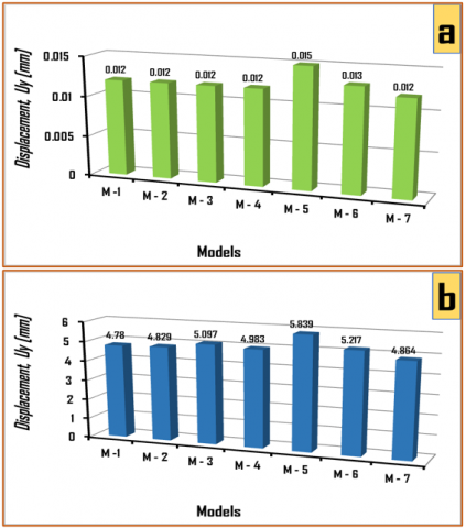
Figure 17(a) compares the maximum tensile displacements towards the y-axis of the seven models. According to the tensile displacement ($U_y$) results, the second model had the lowest value (0.02mm), and the fifth model had the highest value (0.05mm). Figure 17(b) contrasts the maximum compressive displacements of the seven models. The second model had the lowest value (4.829mm), and the fifth model had the highest value (5.839mm), according to the results of the compressive displacements.
Figure 17. Compare the displacement ($U_y$) results for tension and compression sides: (a) Tension side results, (b) Compression side results
Figure 18(a) compares the maximum tensile displacements towards the z-axis of the seven models. The results of the tensile displacement test showed that the second model had the highest value (0.181mm), and the seventh model had the lowest value (0.158mm). The maximum compressive displacements of the seven models are compared in Figure 18(b). According to the results of the compressive displacements, the second model had the lowest value (0.133mm), and the fifth model had the highest value (0.16mm).
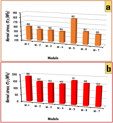
Figure 19(a) compares the maximum values of the normal stresses ($\sigma_{y}$) in the tension side of the seven models. According to the results of the normal stresses ($\sigma_{y}$), the fifth model had the highest value (182MPa), and the seventh model had the lowest value (153MPa). Figure 19(b) shows the maximum values of the normal stresses ($\sigma_{y}$) on the compression side of the seventh models. The first model had the highest value (186MPa), and the third and seventh models had the lowest value (143MPa).
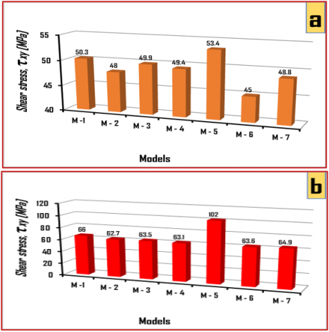
The maximum shear stresses values ($\tau_{x y}$) in the tension side of the seven models are compared in Figure 20(a). The fifth model had the highest value (543MPa), and the sixth model had the lowest value (45MPa), according to the results of the shear stresses ($\tau_{x y}$). The maximum values of the shear stresses ($\tau_{x y}$) on the compression side of the sixth models are shown in Figure 20(b). The second models had the lowest value (62.7MPa), while the fifth model had the highest value (102MPa).
The maximum values of the intensity stresses ($\sigma_{int}$) in the tension side of the seven models are compared in Figure 21(a). The fifth model had the highest value (294MPa), while the second model had the lowest value (161MPa). The maximum values of the intensity stresses ($\sigma_{int}$) on the compression side are shown in Figure 21(b), and the values of these stresses are approximately (0.01MPa) for all models.
Figure 18. Compare the displacement ($U_z$) results for tension and compression sides: (a) Tension side results, (b) Compression side results
Figure 19. Compare the normal stress ($\sigma_{y}$) results for tension and compression sides: (a) Tension side results, (b) Compression side results
Figure 20. Compare the shear stress ($\tau_{x y}$) results for tension and compression sides: (a) Tension side results, (b) Compression side results
Figure 21. Compare the intensity stress ($\sigma_{int}$) results for tension and compression sides: (a) Tension side results, (b) Compression side results
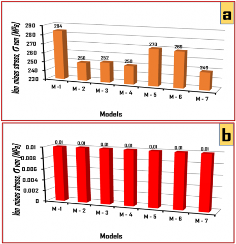
The tension side of the seven models' maximum values of the von mises stress ($\sigma_{von}$) are compared in Figure 22(a). The first model had the highest value of (284MPa), and the seventh model had the lowest value of (249MPa). The maximum values of the von mises stress ($\sigma_{von}$) on the compression side are shown in Figure 22(b), and all models have roughly equal values of mises stress ($\sigma_{von}$), with values of about (0.01MPa).
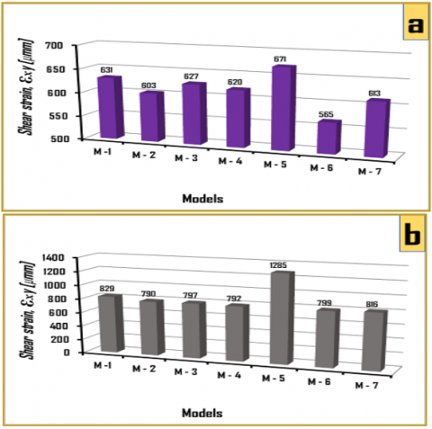
Figure 23(a) shows a comparison between the maximum values of shear strains ($\varepsilon_{x y}$) for the seven models on the tensile side of the models. It appears that the highest shear strain value ($\varepsilon_{x y}$) was in the fifth model and its value (671µmm), while it was the lowest value in the sixth model and its value (585µmm). Figure 23(b) shows a comparison between the maximum values of shear strains ($\varepsilon_{x y}$) for the seven models on the compressive side of the models. It turns out that the highest value of shear strain ($\varepsilon_{x y}$) was in the fifth model and had a value (1235µmm), while being the fifth model's lowest value and its value (792µmm).
Figure 22. Compare the von mises stress ($\sigma_{von}$) results for tension and compression sides: (a) Tension side results, (b) Compression side results
Figure 23. Compare the shear strain ($\varepsilon_{x y}$) results for tension and compression sides: (a) Tension side results, (b) Compression side results
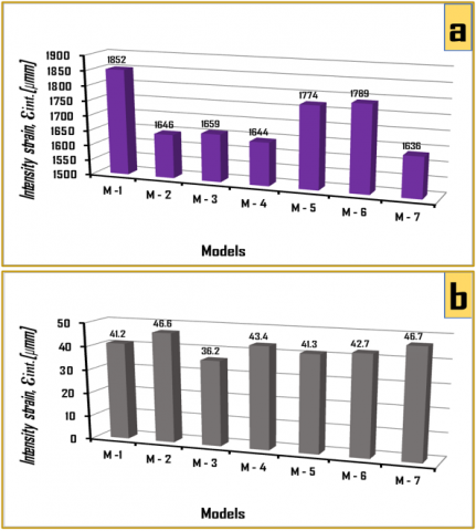
On the tensile side of the models, the maximum intensity strain ($\varepsilon_{int.}$) for the seven models are compared in Figure 24(a). It turns out that the first model's intensity strain ($\varepsilon_{int.}$) value of (1852µmm) had the highest value, while the seventh model's value of (1636µmm) had the lowest value. On the compressive side of the models, Figure 24(b) compares the maximum intensity strain ($\varepsilon_{int.}$) for the seven models. It turns out that the seventh model's value (46.7µmm) had the highest shear intensity strain ($\varepsilon_{int.}$), while the third model's value (36.2µmm) had the lowest value.
Figure 24. Compare the intensity strain ($\varepsilon_{int.}$) results for tension and compression sides: (a) Tension side results, (b) Compression side results
The results of loading the seven models with various loads and of analysing the finite element technique results using the ANSYS program allow us to draw the following conclusions.
(1) To create a safe design, every engineer creating a mechanical design for a component must understand when to use the von mises stress ($\sigma_{ {von }}$) and keep its value less than the yield strength ($\sigma_{y}$) of that material. Using this theory, we note that the yield stress ($\sigma_{y}$) with a value of (370MPa) was equal to the phonon von Mises stress ($\sigma_{ {von }}$) for the first and third models. Using this theory, it was found that the third model (with rectangular openings) was superior to the rest of the models when compared to the first model because its value was the same in both models (370MPa).
(2) According to the maximum shear stress theory, a material will start to fail or give way to failure if its maximum shear stress is equal to or greater than its yield stress value in the uniaxial tensile test. When this theory is applied to the results, we can see that the shear stress values of the seven models were lower than the metal's shear stress yield, which was (370MPa). The second model, with a value of (62.7MPa), was the best one.
(3) The values of the other six models show an increase of varying percentages when compared to the value of the deflection in the first model. This is evident when comparing the values of the first model with the remaining models. These results show that, based on the deflection, the second model is the best and the fifth model is the worst.
(4) The seventh model is the best of all the models, according to the results of the highest values of stress intensity in the seven models. The value of stress intensity was the lowest among the seven models, reaching (261MPa), while the highest value of stress intensity was in the first model, with a value of (294MPa).
(5) The principal stress limit theory is based on the idea that inelastic behavior or failure is controlled by the normal stress limit. The maximum principal stresses ($\sigma_1, \sigma_2$) of the design criterion may not be greater than the working stress ($\sigma_{y}$) of the material. Without fail, this condition must be met ($\sigma_1, \sigma_2 \leq \sigma_y$). From the results obtained for the highest principal stresses values ($\sigma_1, \sigma_2$) for the seven models, and compared with the metal yield stress value ($\sigma_{y}$) to achieve the safety condition ($\sigma_1, \sigma_2 \leq \sigma_y$). It can be seen that this condition is met only by the second, third, seventh and seventh models.
(6) Another conclusion is that all models function safely under maximum strain energy theory, where the value of the principle normal stresses ($\sigma_1, \sigma_2$), were ($\sigma_{M-1}=56 \mathrm{MPa}$, $\sigma_{M-2}=19 \mathrm{MPa}$, $\sigma_{M-3}=111 \mathrm{MPa}$, $\sigma_{M-4}=119 \mathrm{MPa}$, $\sigma_{M-5}=49 \mathrm{MPa}$, $\sigma_{M-6}=89 \mathrm{MPa}$, $\sigma_{M-7}=119 \mathrm{MPa}$), and fulfilling the condition of this theory $\left(\sigma_1^2+{\sigma_2}^2-2 \mu \sigma_1 \sigma_2\leq{\sigma_y}^2\right)$ and this suggests that the seventh and seventh models are the two best models, according to this theory.
The following are some of the most crucial suggestions and areas of future research that should be pursued in this area in order to produce useful outcomes for applications in the different field:
(1) Testing the models in practice to make sure the outcomes align with the computational results of the finite element method. The models were created and tested with the aid of the ANSES program.
(2) Stress and displacement of a tapered cantilever castellated steel beam with circular and octagon openings: a numerical analysis and experiment.
(3) Comparative analysis of the structural performance of steel beams with different opening holes for rolled and castellated structures.
[1] Hadeed, S.M., Alshimmeri, A.J.H. (2019). Comparative study of structural behaviour for rolled and castellated steel beams with different strengthening techniques. Civil Engineering Journal, 5(6): 1384-1394. http://doi.org/10.28991/cej-2019-03091339
[2] Mesquita, L.M.R., Gonçalves, J., Gonçalves, G., Piloto, P.A.G., Kada, A. (2015). Intumescente fire protection of cellular beams. In X Congresso de Construção Metálica e Mista. CMM-Associação Portuguesa de Construção Metálica e Mista, pp. 623-630. http://doi.org/10.13140/RG.2.1.3839.5928
[3] Durif, S., Bouchaïr, A., Vassart, O. (2013). Validation of an analytical model for curved and tapered cellular beams at normal and fire conditions. Periodica Polytechnica Civil Engineering, 57(1): 83-95. https://doi.org/10.3311/PPci.2144
[4] Ghuku, S., Saha, K.N. (2018). Large deflection analysis of curved beam problem with varying curvature and moving boundaries. Engineering Science and Technology, an International Journal, 21(3): 408-420. https://doi.org/10.1016/j.jestch.2018.04.007
[5] Ghuku, S., Saha, K.N. (2016). A theoretical and experimental study on geometric nonlinearity of initially curved cantilever beams. Engineering Science and Technology, an International Journal, 19(1): 135-146. https://doi.org/10.1016/j.jestch.2015.07.006
[6] Cannarozzi, M., Molari, L. (2013). Stress-based formulation for non-linear analysis of planar elastic curved beams. International Journal of Non-Linear Mechanics, 55: 35-47. https://doi.org/10.1016/j.ijnonlinmec.2013.04.005
[7] Chu, P., Li, X.F., Wu, J.X., Lee, K. (2015). Two-dimensional elasticity solution of elastic strips and beams made of functionally graded materials under tension and bending. Acta Mechanica, 226: 2235-2253. https://doi.org/10.1007/s00707-014-1294-y
[8] Salameh, M., Touqan, B. (2023). Comparative analysis of thermal conditions and comfort between modern and traditional districts in Hot-Arid Climate: Case study in Ajman-UAE. International Journal of Computational Methods and Experimental Measurements, 11(3): 169-180. https://doi.org/10.18280/ijcmem.110306
[9] Ghuku, S., Saha, K.N. (2016). An experimental study on stress concentration around a hole under combined bending and stretching stress field. Procedia Technology, 23: 20-27. https://doi.org/10.1016/j.protcy.2016.03.068
[10] Tezcan, M.M., Yetgin, A.G., Canakoglu, A.I., Cevher, B., Turan, M., Ayaz, M., Vasko, M., Handrik, M., Jakubovicova, L., Kopas, P., Blatnicka, M. (2018). MATEC Web of Conferences. Edp Sciences. https://hdl.handle.net/20.500.12619/64904
[11] Szychowski, A. (2015). Stability of cantilever walls of steel thin-walled bars with open cross-section. Thin-Walled Structures, 94: 348-358. https://doi.org/10.1016/j.tws.2015.04.029
[12] De’nan, F., Hasan, H., Mahzuz, M. (2017). Behaviour of the beam to column connection for tapered steel section with perforation. Engineering Heritage Journal, 1(1): 41-44. https://doi.org/10.26480/gwk.01.2017.41.44
[13] Dennis, S.T., Jones, K.W. (2017). Flexural-torsional vibration of a tapered C-section beam. Journal of Sound and Vibration, 393: 401-414. https://doi.org/10.1016/j.jsv.2017.01.017
[14] Akbarzade, M., Farshidianfar, A. (2017). Nonlinear dynamic analysis of an elastically restrained cantilever tapered beam. Journal of Applied Mechanics and Technical Physics, 58: 556-565. https://doi.org/10.1134/S002189441703021X
[15] Durif, S., Bouchair, A., Vassart, O. (2013). Experimental tests and numerical modeling of cellular beams with sinusoidal openings. Journal of Constructional Steel Research, 82: 72-87. https://doi.org/10.1016/j.jcsr.2012.12.010
[16] Tan, L., Wang, G., Ren, T., Dou, L., Yang, X., Song, S. (2021). Stress distribution and mechanical behaviour of rock mass containing two openings underground: Analytical and numerical studies. Geofluids, 2021: 1-16. https://doi.org/10.1155/2021/1917443
[17] Kim, H.G., Lee, Y.J., Kim, K.H. (2022). Cyclic flexural performance of RC beams with small circular openings in plastic hinge region. Construction and Building Materials, 321: 126339. https://doi.org/10.1016/j.conbuildmat.2022.126339
[18] Ferreira, F.P.V., Martins, C.H., De Nardin, S. (2020). Advances in composite beams with web openings and composite cellular beams. Journal of Constructional Steel Research, 172: 106182. https://doi.org/10.1016/j.jcsr.2020.106182
[19] Eryiğit, E., Zor, M., Arman, Y. (2009). Hole effects on lateral buckling of laminated cantilever beams. Composites Part B: Engineering, 40(2): 174-179. https://doi.org/10.1016/j.compositesb.2008.07.005
[20] Mezher, N.A.M., Noori, A.R., Ertürkmen, D. (2023). Influence of the web opening shapes on the bending and free vibration responses of castellated steel beams. International Journal of Engineering Technologies IJET, 8(2): 83-100. https://doi.org/10.19072/ijet.1273137
[21] Sayyad, A.S., Shaikh, A.S. (2020). Estimation of deflections in cantilever and fixed castellated beams with hexagonal, square and circular openings. TECNICA ITALIANA-Italian Journal of Engineering Science, 64(1): 118-127. https://doi.org/10.18280/ti-ijes.640118
[22] Sirisonthi, A., Julphunthong, P., Joyklad, P., Suparp, S., Ali, N., Javid, M.A., Chaiyasarn, K., Hussain, Q. (2021). Structural behavior of large-scale hollow section RC beams and strength enhancement using Carbon Fiber Reinforced Polymer (CFRP) Composites. Polymers, 14(1): 158. https://doi.org/10.3390/polym14010158
[23] Al-Shamayleh, R., Al-Saoud, H., Alqam, M. (2022). Shear and flexural strengthening of reinforced concrete beams with variable compressive strength values using externally bonded carbon fiber plates. Results in Engineering, 14: 100427. https://doi.org/10.1016/j.rineng.2022.100427
[24] Karash, E.T. (2011). Modelling of unilateral contact of metal and fiberglass shells. Applied Mechanics and Materials, 87: 206-208. https://doi.org/10.4028/www.scientific.net/AMM.87.206
[25] Karash, E.T., Alsttar Sediqer, T.A., Elias Kassim, M.T. (2021). A comparison between a solid block made of concrete and others made of different composite materials. Revue des Composites et des Matériaux Avancés, 31(6): 341-347. https://doi.org/10.18280/rcma.310605
[26] Elias Kassim, M.T., Karash, E.T., Sultan, J.N. (2023). A mathematical model for non-linear structural analysis reinforced beams of composite materials. Mathematical Modelling of Engineering Problems, 10(1): 311-333. https://doi.org/10.18280/mmep.100137
[27] Karash, E.T., Slewa, M.Y., AL-Maula, B.H. (2023). State stress analysis of dental restoration materials using the ANSYS program. Revue des Composites et des Matériaux Avancés, 33(3): 183-192. https://doi.org/10.18280/rcma.330306
[28] Karash, E.T., Sultan, J.N., Najem, M.K. (2022). The difference in the wall thickness of the helicopter structure are made of composite materials with another made of steel. Mathematical Modelling of Engineering Problems, 9(2): 313-324. https://doi.org/10.18280/mmep.090204
[29] Ali, S.A., Hromadka, T.V. (2023). Comparison of current complex variable boundary element method (CVBEM) capabilities in basis functions, node positioning algorithms (NPAs), and coefficient determination methods. International Journal of Computational Methods and Experimental Measurements, 11(3): 143-148. https://doi.org/10.18280/ijcmem.110302
[30] Najem, M.K., Karash, E.T., Sultan, J.N. (2022). The amount of excess weight from the design of an armored vehicle body by using composite materials instead of steel. Revue des Composites et des Materiaux Avances, 32(1): 1-10. https://doi.org/10.18280/rcma.320101
[31] ANSYS Engineering Data. (2017). Composite materials library: Canonsburg, PA, USA.
[32] Waqas, H.M., Shi, D., Imran, M., Khan, S.Z., Tong, L., Ahad, F.E., Zaidi, A.A., Iqbal, J., Ahmed, W. (2019). Conceptual design of composite sandwich structure submarine radome. Materials, 12(12): 1966. https://doi.org/10.3390/ma12121966
[33] Rangaswamy, T., Vijayrangan, S. (2005). Optimal sizing and stacking sequence of composite drive shafts. Materials Science, 11(2): 133-139.