Louay A. Mahdi*![]() | Muna K. J. AL-Naamee
| Muna K. J. AL-Naamee![]() | Ahmed Q. Salam | Salman H. Omran
| Ahmed Q. Salam | Salman H. Omran![]() | Hind A. AL-Salihi
| Hind A. AL-Salihi![]() | Marwa K. Abood
| Marwa K. Abood![]() | Hasanain A. Abdul Wahhab
| Hasanain A. Abdul Wahhab![]()
This article is part of the Special Issue Ajman 6th International Environment Conference
© 2023 IIETA. This article is published by IIETA and is licensed under the CC BY 4.0 license (http://creativecommons.org/licenses/by/4.0/).
OPEN ACCESS
Using an entropy generation analysis, heat exchangers can be designed with optimal efficiency. This study delves into the irreversibility of forced convection heat transfer and friction flow around a horizontal cylinder, revealing that pressure drops induce entropy generation that varies in accordance with Reynolds numbers. The investigation encompasses four groups of ReD, covering ranges of 0.4<ReD<4, 4<ReD<40, 40<ReD<4000, and 4000<ReD<40000. The study aims to elucidate the relationship between the entropy generation number (Ns), ReD, the irreversibility distribution ratio (∅), the optimal Reynolds number (ReD,opt), and the Bejan number (Be), particularly where entropy generation has a minimal effect. Additionally, it seeks to determine the relationship between the duty parameter and ReD,opt across all ReD ranges. The findings highlight the optimum design point for forced convection around a horizontal cylinder. At this point, the entropy generation number reaches its minimum value when Ns=1 and the ratio ReD/ReD,opt=1, marking the optimal point for irreversibility or entropy generation. At this juncture, the irreversibility distribution ratio ∅ equals 0.5, and the optimal Bejan number stands at 0.667.
entropy generation analysis, external flow, horizontal cylinder, force convection
Due to the decrease in natural energy-producing resources, the focus has shifted to thermal system efficiency and the conservation of energy resources. From here, the second law of thermodynamics has become a fundamental guide for engineers and designers when analyzing and improving engineering systems. According to the second law of thermodynamics, real systems are inevitably characterized by a loss of available work. Compared to an ideal (lossless) process, thermodynamic efficiency decreases as available work is lost.
Entropy, as a thermodynamic property, indicates how much atomic disorder there is in a system. A system with a high degree of molecular disturbance has a very high entropy value. Conversely, a system with a very low level of molecular disturbance has a very low entropy value. Efficiency is defined by the FLT (first law of thermodynamics) as the ratio of the working power and the total heat input to the system, which does not give much information about whether the available energy (irreversibility) is effective or not. In a thermal system, attention should be paid to improving energy efficiency by analyzing lost energy, which can be assessed using the second law. The SLT (second law of thermodynamics) is applied to study irreversibility in terms of the rate at which entropy occurs when the distributed energy is proportionate to entropy generation. Entropy generation analysis has key characteristics that make it more appealing than traditional energy balance approaches. Entropy generation analysis can, in principle, be used for any energy conversion mechanism and help get the optimal thermal working point [1].
Entropy generation is estimated using two well-known methods. The first method estimates local entropy generation at each point in the studied system. Total entropy generation can also be determined by a process in which the distribution of local entropy generation over volume is integrated [2]. The second method uses the relations between the friction factor and the Nusselt number to evaluate total entropy generation. This method does not need to solve the momentum and energy equations since the Nusselt number and friction factor values are known.
Specifically, Bejan [3] modeled external flow irreversibility (entropy generation) for a horizontal heated tube, and the ReD model (based on Poulikakos and Johnson [4], which modeled mass and heat transfer flow around a cylinder and across a plane surface. The study covers the 40<ReD<1000 range only. Bejan [5, 6] found the relation between the ReD,opt, and β (duty number) for the range of Re (40<ReD<105). Besides this, Bejan [7] introduced a dimensionless parameter for the irreversibility distribution ratio called Be (Bejan Number). This parameter illustrates how forced convection heat transfer irreversibility and friction irreversibility operate in the same ReD range. Mahdi et al. [8] study theorticaly and expermantly the heat transfer from horizontal cylinder by natural convection and radiation.
The aim of this study is to analyze the entropy generation w ith four ranges 0.4<ReD<4, snd not like the privous steady which 4<ReD<40, 40<ReD<4000 combines all ranges in one group. It has the benefit of determining the behavior of entropy generation in each range and for engineering applications like refrigeration and air conditioning where the heat exchangers working for low capacity like 4000<ReD<40000 the refrigerators or freezers the ReD range is 4<ReD<40 or 40<ReD <4000 while for high capacity like the air cooled cillers the ReD range 4000<ReD<40000.
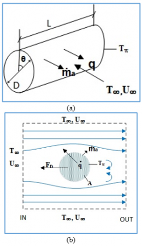
The steady-state external flow around the horizontal cylinder and entropy generation rate is controlled in volume as shown in Figure 1.
Figure 1. External flow convection heat transfer. (a) Shape geometry. (b) Control volume
Mass balance [5]:
$\dot{m}_{in }=\dot{m}_{out}=\dot{m}$ (1)
Heat balance [5]:
$\dot{m}_{in} h_{in}-\dot{m}_{out} h_{out}+\iint q^{\prime \prime} d A=0$ (2)
Entropy generation balance [5]:
$\dot{S}_{gen}=\dot{m}_{out} S_{out}-\dot{m}_{in} s_{ in }-\iint \frac{q^{\prime \prime} d A}{T_s}$ (3)
The Gibbs equation is given as [4]:
$d h=T d S+V d P$ (4)
Applying the Gibbs Eq. (4) for the control volume in Figure 1 with Eq. (2) gives:
$\begin{aligned} \dot{m}_{in} h_{in}-\dot{m}_{out} h_{out } &=T_{\infty}\left(\dot{m}_{\text {out }} s_{out}-\dot{m}_{in} s_{in}\right) +\frac{m_{in}}{\rho_{\infty}}\left(P_{out}-P_{in}\right)\end{aligned}$ (5)
Following the studies [5-7], it is assumed that the average quantities of the control volume are equal to the free stream quantities. Combining Eq. (1) with Eq. (5) and substituting into Eq. (3) yields:
$\dot{S}_{\text {gen }}=\iint q^{\prime \prime}\left(\frac{1}{T_{\infty}}-\frac{1}{T_s}\right) d A-\dot{m}_{\text {in }} \frac{P_{\text {out }}-P_{\text {in }}}{\rho_{\infty} T_{\infty}}$ (6)
The flow rate and the drag force may be given as:
$\dot{m}=A_{cross} \rho_{\infty} U_{\infty}$ and $F=A_{cross}\left(P_{in}-P_{out}\right)$ (7)
Eq. (7) substituting in Eq. (6) to find:
$\dot{S}_{g e n}=\iint q^{\prime \prime}\left(\frac{1}{T_{\infty}}-\frac{1}{T_s}\right) d A+\frac{U_{\infty} F}{T_{\infty}}$ (8)
Assuming $\left|T_s-T_{\infty}\right| \ll T_{\infty}$ or $T_s$, and neglecting the higher order, Eq. (8) by Taylor series becomes:
$\dot{S}_{g e n}=\frac{1}{T_{\infty}^2} \iint q^{\prime \prime} \cdot\left(T_s-T_{\infty}\right) \cdot d A+\frac{U_{\infty} \cdot F}{T_{\infty}}$ (9)
On the right, the first term shows the irreversibility due to forced convection heat transfer and the second term represents the irreversibility due to friction:
The drag force per unit length, F/l [6, 9]:
$\begin{aligned} F / l=\int_0^\pi \frac{1}{2} \rho_{\infty} U_{\infty}^2 C_{D, x} r d \theta =\frac{1}{2} \rho_{\infty} U_{\infty}^2 \frac{D}{2} \int_0^\pi C_{D . x} d \theta\end{aligned}$ (10)
The temperature difference due to heat fluxes can equal to:
$\frac{q^{\prime \prime}}{\alpha}=T_s-T_{\infty}$ (11)
Using Eqs. (10) and (11) and substituting into Eq. (9):
$\frac{\dot{S}_{g e n}}{l}=\frac{q^{\prime 2}}{T_{\infty}^2} 2 \frac{D}{2} \int_0^\pi \frac{d \theta}{\alpha}+\frac{U_{\infty}^3 \rho_{\infty}}{2 T_{\infty}} \frac{D}{2} 2 \int_0^\pi C_{D, x} d \theta$ (12)
where, $\alpha=a \operatorname{Re}_D^m \operatorname{Pr}^{\mathrm{n}} \frac{\mathrm{k}_{\infty}}{\mathrm{D}} ;$ and $\int_0^\pi C_{D, x} d \theta=C_f$ following [4, 9].
$C_D=\mathrm{b} \operatorname{Re}_D^{-y}$ (13)
Substituting Eqs. (11) and (13) into (12) yields:
$\begin{gathered}\frac{\dot{S}_{g e n}}{l}=\frac{q^{\prime \prime 2}}{T_{\infty}^2} \frac{D^2 \operatorname{Re}_D^{-m} \operatorname{Pr}^{-n}}{a k_{\infty}} \int_0^\pi d \theta+\frac{U_{\infty}^3 \rho_{\infty} D}{2 T_{\infty}} b R e_D^{-y} \\ \frac{\dot{S}_{g e n}}{l}=\frac{q^{\prime \prime 2}}{T_{\infty}^2} \frac{D^2 \operatorname{Re}_D^{-m} \operatorname{Pr}^{-n}}{a k_{\infty}} \pi+\frac{U_{\infty}^3 \rho_{\infty} D}{2 T_{\infty}} b R e_D^{-y}\end{gathered}$ (14)
where, $q^{\prime}=\frac{q}{l}=q^{\prime \prime} \pi D \rightarrow q^{\prime \prime}=\frac{q^{\prime}}{\pi D} \rightarrow q^{\prime \prime 2}=\frac{q^{\prime 2}}{\pi^2 D^2}$, and $R e_D=$ $\frac{\rho U D}{\mu} U=\frac{R e_D \mu}{\rho D}$.
These definitions will be used into Eq. (14):
$\frac{\dot{S}_{g e n}}{l}=\frac{1}{a \pi} \frac{q^{\prime 2}}{T_{\infty}^2} \frac{P r^{-n}}{k_{\infty}} R e_D^{-m}+\frac{b}{2} \frac{U_{\infty}^2 \mu_{\infty}}{T_{\infty}} R e_D^{1-y}$ (15)
The general form for external flow irreversibility (entropy generation) around a cylinder is represented in Eq. (15), and the values of n, a, and m are shown in Table 1 depending on the references [10, 11]:
Table 1. Constant for Eq. (15)
|
Range of ReD |
Nusselt Number |
a |
m |
n |
|
0.4 – 4 |
Nu = 0.989* ReD0.33 *Pr 1/3 |
0.989 |
0.33 |
1/3 |
|
4 – 40 |
Nu = 0.911* ReD0.385 *Pr 1/3 |
0.911 |
0385 |
1/3 |
|
40 – 4000 |
Nu = 0.683* ReD0.466 *Pr 1/3 |
0.683 |
0.466 |
1/3 |
|
4000 – 40000 |
Nu = 0.193* ReD0.618 *Pr 1/3 |
0.193 |
0.618 |
1/3 |
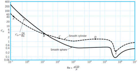
Drag coefficients are a function of ReD. The values needed for that are obtained by fitting curves to the ReD range as in the Nu equations above. The map from reference [12], Figure 2, is used to define the constants b and y in Eq. (13) by curve fitting and the standard errors and correlations coefficients is shown in Table 2.
Figure 2. The relation between the Re and CD (drag force coefficient) for force flow around cylinder [12]
Table 2. Drag coefficient correlations
|
Range of ReD |
Drag Coefficient |
Standard Error / Correlation Coefficient |
b |
y |
|
0.4 – 4 |
CD =10.17 ReD-0.784 |
0.77033/0.999 |
10.17 |
-0.784 |
|
4 – 40 |
CD =6.634 ReD-0.302 |
0.08111/0.996 |
6.634 |
-0.302 |
|
40 – 4000 |
CD =4.681 ReD-0.2 |
0.07636/0.997 |
4.861 |
-0.2 |
|
4000 – 40000 |
CD =1.1 |
|
|
|
New form of Eq. (15) will be as follow:
0.4<ReD<4:
$\frac{\dot{S}_{g e n}}{l}=0.322 \frac{q^{\prime 2}}{T_{\infty}^2} \frac{P r^{-\frac{1}{3}}}{k} R e_D^{-0.33}+5.085 \frac{\mu_{\infty} U_{\infty}^2}{T_{\infty}} R e_D^{0.216}$ (16)
4<ReD<40:
$\begin{aligned} \frac{\dot{S}_{g e n}}{l}= & 0.349 \frac{q^{\prime 2}}{T_{\infty}^2} \frac{P r^{-\frac{1}{3}}}{k} \operatorname{Re}_D^{-0.385}+ 3.317 \frac{\mu_{\infty} U_{\infty}^2}{T_{\infty}} \operatorname{Re}_D^{0.698}\end{aligned}$ (17)
40<ReD<4000:
$\frac{\dot{S}_{g e n}}{l}=0.466 \frac{q^{\prime 2}}{T_{\infty}^2} \frac{P r^{-\frac{1}{3}}}{k} R e_D^{-0.466}+2.3405 \frac{\mu_{\infty} U_{\infty}^2}{T_{\infty}} R e_D^{0.8}$ (18)
4000<ReD<40000:
$\frac{\dot{S}_{g e n}}{l}=1.649 \frac{q^{\prime 2}}{T_{\infty}^2} \frac{P r^{-\frac{1}{3}}}{k} R e_D^{-0.618}+0.55 \frac{\mu_{\infty} U_{\infty}^2}{T_{\infty}} R e_D$ (19)
The optimum Reynolds number (ReD,opt) can be found in the Eqs. (16)-(19) can be found by diverting these equations with respect to Reynolds number as follows:
0.4<ReD<4:
$R e_{\text {Dopt }}=0.139 \beta^{\frac{1}{0.546}}$ (20)
4<ReD<40:
$R e_{\text {Dopt }}=0.722 \beta^{\frac{1}{1.083}}$ (21)
40<ReD<4000:
$R e_{\text {Dopt }}=1.824 \beta^{\frac{1}{1.266}}$ (22)
4000<ReD<40000:
$R e_{\text {Dopt }}=14.64 \beta^{\frac{1}{1.618}}$ (23)
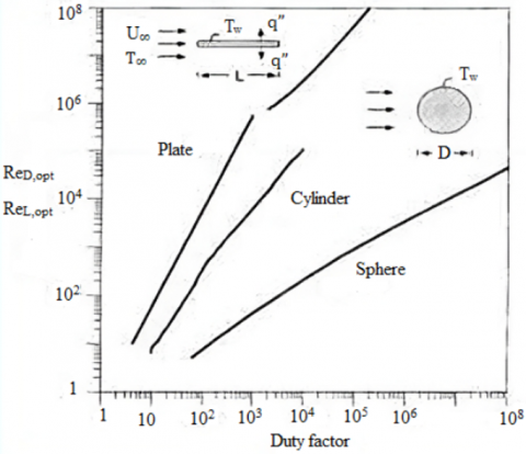
The duty parameter β in Eqs. (20)-(23) is found. The duty parameter is defined by the ratio between the irreversibility due to convection and the irreversibility due to pressure drop [5-7] and is represented in Figure 3. By finding the duty factor the optimum ReD,opt can be get from the figure which is helpful to go to fond the most important parameter that is the entropy generation number Ns :
$\beta=\frac{q^{\prime^2}}{U_{\infty}^2\,\, k_{\infty}\,\, \mu_{\infty}\,\, T_{\infty}\,\, P r^n}$ (24)
Figure 3. The relation between ReD,opt and Duty factor [5, 6]
The irreversibility distribution ratio ∅ defines: fluid friction irreversibility due to pressure drop in relation to force convection and heat transfer irreversibility [5, 6].
Bejan number Be: which is the alternative distribution parameter. This parameter is defined by the ratio of the irreversibility due to force convection heat transfer to the summation of the irreversibility due to force convection heat transfer and friction due to pressure drop [7]:
$B e=\frac{1}{1+\varnothing}$ (25)
where, Be=1 is the limit at which heat transfer irreversibility dominates, Be=0 is the opposite limit at which friction irreversibility is dominated by fluid effects, and Be=1/2 is the case in which the heat transfer and fluid friction entropy generation rates are equal.
Substitute ReD,opt: Eq. (20) in Eq. (16), Eq. (21) in Eq. (17), Eq. (22) in Eq. (18), finally Eq. (23) in Eq. (19) to find new entropy generation number, Ns:
0.4<ReD<4:
$N_{s 1}=\frac{\dot{S}_{gen}}{\dot{S}_{gen.min}}=\left(\frac{R e_D}{R e_{Dopt\,\,}}\right)^{-0.33}+\left(\frac{R e_D}{R e_{Dopt\,\,}}\right)^{0.216}$ (26)
4<ReD<40:
$N_{s 2}=\frac{\dot{S}_{g e n}}{\dot{S}_{gen.min}}=\left(\frac{R e_D}{R e_{Dopt\,\,}}\right)^{-0.385}+\left(\frac{R e_D}{R e_{Dopt\,\,}}\right)^{0.698}$ (27)
40<ReD<4000:
$N_{s 3}=\frac{\dot{S}_{g e n}}{\dot{S}_{gen.min}}=\left(\frac{R e_D}{R e_{Dopt\,\,}}\right)^{-0.466}+\left(\frac{R e_D}{R e_{Dopt\,\,}}\right)^{0.8}$ (28)
400<ReD<4000:
$N_{s 4}=\frac{\dot{s}_{g e n}}{\dot{s}_{\text {gen.min }}}=\left(\frac{R e_D}{R e_{\text {Dopt}}}\,\, \right)^{-0.618}+\left(\frac{R e_D}{R e_{\text {Dopt}}}\,\, \right)$ (29)
As the above forms result in Ns=2 where heat transfer and pressure drop occur simultaneously, the entropy generation number must be Ns=1. This combines force convection with heat transfer irreversibility and friction drop due to pressure drop irreversibility. Now let's consider Eqs. (6) and (7) how to represent the irreversibility of heat transfer due to forced convection and the irreversibility of pressure drop due to friction as percentages. Pareto theory is the key, and Eqs. (26)-(29) will be:
0.4<ReD<4:
$N_{s 1}=\frac{\dot{S}_{gen }}{\dot{S}_{gen.min}}=\frac{2}{3}\left(\frac{R e_D}{R e_{Dopt\,\,}}\right)^{-0.33}+\frac{1}{3}\left(\frac{R e_D}{R e_{Dopt\,\,}}\right)^{0.216}$ (30)
4<ReD<40:
$N_{s 2}=\frac{\dot{S}_{\text {gen }}}{\dot{S}_{\text {gen.min }}}=\frac{2}{3}\left(\frac{R e_D}{R e_{\text {Dopt}}}\,\, \right)^{-0.385}+\frac{1}{3}\left(\frac{R e_D}{R e_{\text {Dopt}}}\,\, \right)^{0.698}$ (31)
0<ReD<4000:
$N_{s 3}=\frac{\dot{S}_{gen}}{\dot{S}_{gen.min}}=\frac{2}{3}\left(\frac{R e_D}{R e_{Dopt\,\,}}\right)^{-0.466}+\frac{1}{3}\left(\frac{R e_D}{R e_{Dopt\,\,}}\right)^{0.8}$ (32)
4000<ReD<40000:
$N_{S 4}=\frac{\dot{S}_{gen}}{\dot{S}_{gen.min }}=\frac{2}{3}\left(\frac{R e_D}{R e_{Dopt\,\,}}\right)^{-0.618}+\frac{1}{3}\left(\frac{R e_D}{R e_{Dopt\,\,}}\right)$ (33)
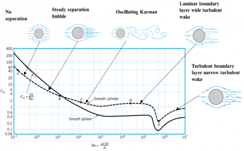
The flow pattern around the horizontal cylinder for each range of ReD is different, as shown in Figure 4.
Figure 4. The flow pattern around cylinder [12]
Heat transfer by force convection causes irreversibility (entropy generation) depending on the flow stability around the cylinder. The first range of ReD shows low velocity and no flow separation. While the second Reynolds range represents steady separation. The third generation of ReD generation is characterized by unsteady vortex shedding. The fourth range of ReD produces a laminar boundary layer with a wide turbulent wake. Finally, in the fifth range of ReD shows that the turbulent boundary layer appears with a narrow turbulent wake.
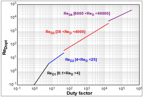
Figure 5 shows β (the duty factor and ReD,opt for four ranges of Re groups. The duty factor and ReD,opt are directly proportional. The value increases for higher ReD ranges than for smaller ranges. By finding the duty number, the ReD,opt be known. Then can calculate the number of entropy generation by dividing the real ReD by the ReD,opt . The figure completes and clarifies the relation better than Figure 3 for reference, which does not cover the low Reynolds number below 50. For the lower ReD ranges 0.4< ReD < 4 and 4< ReD < 40, there was a small change in the duty factor and the ReD. This suggests that these two ranges are indicative of natural convection rather than forced convection. The reason for the change can be related to the type of flow around the cylinder, as shown in Figure 4. The gap between the second ReDrange and the third represents the change in flow pattern from laminar to turbulent. For the ReD ranges 40 < ReD < 4000 and 4000 < ReD < 40000, the duty factor change is bigger than that for the previous two ranges.
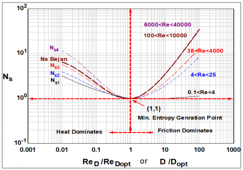
Figure 6 shows the ratio of ReD to ReD,opt and Ns for all Reynolds range groups and Bejan results. Parabolic shapes represent these relations. As Ns=1 and ReD/ReD,opt=1, the lowest entropy generation occurs at this point. The left side of this optimum point indicates the irreversibility effect of heat transfer, while the right side represents the irreversibility effect of pressure drop [5, 6].
The Bejan result matches ReD's highest range. The friction irreversibility part corresponds to the highest range, while the heat irreversibility part corresponds to the fourth and third highest ranges. The figure 6 can be used to clarify the Ns for any ratio of ReD and ReD,opt, and the position of the system analysis will show the effect of each entropy generation, heat or friction.
Figure 5. Optimum Reynolds number and duty parameter relation for forced convection around horizontal cylinder
Figure 6. The relation between entropy generation number Ns and ReD/ReD,opt
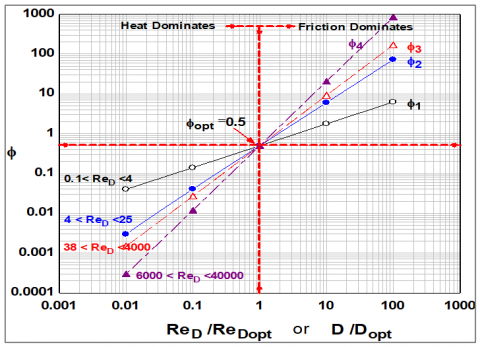
The ∅ irreversibility distribution ratio is defined as the ReD ratio shown in Figure 7. The optimum value of ∅opt = 0.5 at the lowest effect of heat transfer irreversibility and friction irreversibility for all groups of ReD is the optimum point.
The optimal value of ∅ occurs when the ratio ReD/ReD,opt = 1, where the irreversibility of heat transfer effect equals 2/3 and the irreversibility of pressure drop effect equals 1/3.
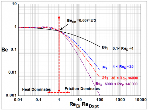
Figure 8 illustrates the relationship between the Bejan number (Be) and ReD/ReDopt which is another irreversibility distribution factor. The optimum point occurs when ReD/ReDopt=1, Beopt=0.667. The heat irreversibility condition on the left causes all flow paths to act close to Be=1. At friction, the irreversibility effect is on the right side, however, drops below Be=1 until zero. This matches the Bejan number definition.
Figure 7. The relation between ReD/ReD,opt and Irreversibility distribution ratio
Figure 8. The relation between Bejan number and ReD/ReD,opt
The irreversibility of force convection heat transfer and friction flow for a horizontal cylinder is studied and classified into four groups. The results are:
The entropy generation for forced convection around a horizontal heated cylinder is represented in four Reynolds number ranges.
The relation shape is the same for all ranges but different in values which mean it is important to find the entropy generation number for each range separately.
The optimum entropy generation number for all Reynolds number ranges via ReD / ReD,opt is done at Ns=1 and ReD /ReD,opt=1. in this point the entropy generation is lowest and the design of any heat exchangers must be near this point.
The thermal system optimum point is found at Be, opt =0.667 where the lowest irreversibility of heat transfer and pressure drop is reached when Ns =1, and ReD/ ReD,opt =1, and ∅opt = 0.5.
At low Reynolds range, Reynolds number for heat transfer is not correct. It is actually the irreversibility of natural convection and radiation that is absent.
|
Symbol |
Definition |
Unit |
|
A |
Area |
m2 |
|
Be |
Bejan number |
|
|
Cf |
Drag force coefficient |
|
|
Cf,x |
Local Drag force coefficient |
|
|
D |
Cylinder diameter |
m |
|
F |
Drag force |
N |
|
H |
Enthalpy |
kJ.kg-1 |
|
K |
Thermal conductivity |
W.m-1.C-1 |
|
L |
Length |
m |
|
$\dot{m}$ |
Mass flow rate |
Kg.sec-1 |
|
Ns |
Entropy generation number |
|
|
Nu |
Nusselt number |
|
|
P |
Pressure |
Pa |
|
Pr |
Prandtl number |
|
|
q |
Heat flux |
W |
|
$\dot{q}$ |
Heat flux per length |
W.m-1 |
|
$\ddot{q}$ |
Heat flux per area |
W.m-2 |
|
ReD |
Reynolds number around cylinder |
|
|
ReD,opt |
Optimum Reynolds number around cylinder |
|
|
r |
Radius |
m |
|
Sgen |
Entropy generation rate |
W.K-1 |
|
T |
Temperature |
K |
|
U |
Velocity |
m.sec-1 |
|
Greek letters |
||
|
β |
Duty number |
|
|
∅ |
Irreversibility distribution number |
|
|
μ |
Dynamic viscosity |
m2.sec-1 |
|
θ |
Angle |
degree |
|
ρ |
Density |
Kg.m-3 |
|
α |
Heat transfer coefficient |
W.m-2.C-1 |
|
Subscript |
||
|
in |
inlet |
|
|
out |
outlet |
|
|
∞ |
free stream |
|
|
s |
surface |
|
|
x |
local |
|
|
cross |
cross-section |
|
[1] Sciacovelli, A., Verda, V., Sciubba, E. (2015). Entropy generation analysis as a design tool—A review. Renewable and Sustainable Energy Reviews, 43: 1167-1181. https://doi.org/10.1016/j.rser.2014.11.104
[2] Martyushev, L.M. (2013). Entropy and entropy production: Old misconceptions and new breakthroughs. Entropy, 15(4): 1152-1170. https://doi.org/10.3390/e15041152
[3] Bejan, A. (1982), Entropy Generation Through Heat and Flow Fluid Flow. John Wiley & Sons, Inc.
[4] Poulikakos, D., Johnson, J.M. (1989). Second law analysis of combined heat and mass transfer phenomena in external flow. Energy, 14(2): 67-73. https://doi.org/10.1016/0360-5442(89)90080-7
[5] Bejan, A. (1996). Entropy Generation Minimization. 1st Edition, CRC Press LLC.
[6] Bejan, A., Tsatsaronis, G., Moran, M.J. (1995). Thermal Design and Optimization. John Wiley & Sons.
[7] Bejan, A. (2006). Advanced Engineering Thermodynamics. 3rd Edition, John Wiley & Sons, Inc.
[8] Mahdi, L.A.A.A., Fayad, M.A., Chaichan, M.T. (2023). Analysis of entropy generation for horizontal heated cylinder by natural convection and radiation. EVERGREEN Joint Journal of Novel Carbon Resource Sciences & Green Asia Strategy, 10(2): 888-896. http://dx.doi.org/10.5109/6792884
[9] Khan, W.A., Culham, J.R., Yovanovich, M.M. (2005). Fluid flow around and heat transfer from an infinite circular cylinder. Journal of Heat transfer, 127(7): 785-790. https://doi.org/10.1115/1.1924629
[10] DeWitt, I., Lavine, B. (2007). Introduction to Heat Transfer. 5th Edition. John Wiley & Sons, Inc.
[11] Çengel, Y. (2002). Heat Transfer a Practical Approach. 2nd Edition. McGraw – Hill.
[12] Munson, B.R., Young, D.F., Okiishf, T.H. (2002). Fundamental of Fluid Mechanics. 4th Edition, John Wiley &Sons Inc.