ACCESS
An energy supply system has been designed by combining the batteries with Ultracapacitor (UC) characterized as hybrid energy storage system (HESS) for a Hybrid Electric Vehicle (HEV) / Electric Vehicle (EV). The main aim of this paper is to design an efficient and intelligent controller for a smooth switching between the two sources of HESS. In this work, UC is used to meet the peak power requirement and average power can be supplied by the battery, acts as a major source. Corresponding to the speed of an Electric motor the math function (MFB) based controller has been designed with four individual math functions. To achieve the main objective, the designed MFB controller is combined with conventional Proportional-Derivative (PD) results in the formation of a hybrid controller which is used to generate the required switching signals to the particular converter corresponding to the vehicle dynamics. Finally, the entire circuit has been designed with the hybrid controller and simulated in MATLAB/Simulink, all measured values are presented and which shows the controller action for different modes of the electric motor.
proportional-derivative controller, math function-based controller, ultracapacitor, battery
Petrol is one of the major fossil fuels for vehicle propulsion; all vehicles are made with IC Engine which demands the petrol/diesel for its proper operation. Several drawbacks have associated with IC engine based vehicle, in that pollution is the main problem and cost of fuel also more. If the usage of this fossil fuel is increasing day to day after some years it will disappear. In order to preserve some amount of fossil fuel like crude oil for future generation must have to take a diversion from the use of fossil fuel with other alternative fuel of effective working condition. After doing several types of research on replacing petrol or diesel engine with other alternative source, scientists have introduced battery as a part of the source which can be made the possibility to replace IC engine by an electric motor. These attempts have given pollution-free vehicle called an electric vehicle with some major cons. Driving range is one of the major problems with battery feeding vehicle and also during climbing of hill roads it requires extra power for its successful operation than regular roads and to avoid these, extra powered batteries are required it will increases the size, weight, and cost of the vehicle.
UC has been introduced in electric vehicle application to utilize its inherent high power density property, on another hand; it is having low energy density. The high power density of UC is taken as an advantage to improve the main source of life by supplying the power to the electric vehicle. Generally, UC has been connected to one end of BDC. HESS has been introduced by combining the two sources battery and UC here battery acts as a major source and UC acts as a minor source by supplying power to the vehicle during transient periods and staring of a vehicle. Electric vehicle with HESS has given a better result than battery only feeds electric vehicle. In HESS based electric vehicle switching between the two sources is the major problem. Several controls have been introduced and designed like fuzzy logic, neuro-fuzzy, artificial intelligence and some other conventional controllers like PI, PID etc.
Anciently Battery is used to propel the electric vehicle in all road conditions like starting, running and transient period of the vehicle. A hybrid flywheel/battery system is used for storing the braking energy and it can be utilized during peak loads of electric vehicles in order to reduce the burden on the battery (Lustenader et al., 2015). The embedded energy storage system has been made with Fuel cell and UC, a polynomial method is used to split the energy between two sources according to the energetic request of HEV. A fuel cell is used for meeting the average power and UC is used for fluctuating for the requirement of HEV (Tani et al., 2013). The energy management between high energy density device battery and high power density device UC has been made with the controller for emergency starting of an IC engine to save the life of the rich energy device. In the designed power source UC gets charged from the battery very quickly and discharges energy at the same rate which makes the IC engine proper starting (Averbukh et al., 2015).
The HESS has been developed for EV/HEV application in that, energy management is the main issue to split the energy between battery and UC. Energy management strategy has developed with an adaptive fuzzy logic controller to manage the power splitting between the two sources. The designed adaptive fuzzy logic controller enhances the overall system efficiency by sharing the transient power to the UC and average power to the battery (Yin et al., 2016).To make proper energy management between the battery and UC 2- real-time controllers have been developed for finest current sharing between UC and battery in EV application.one of the controller is developed based on Karush–Kuhn–Tucker conditions by solving the formulated optimization problem, which makes the right current splitting of HESS. The second controller is developed based on neural network and that is termed as an intelligent controller. Based on the current sharing of energy sources controller performance has been evaluated (Shen et al., 2016). With a variable rate –limit function an adaptive energy management control has been designed for the energy storage system. The designed energy sharing controller saving the life of the main source of the energy storage system (ESS). Steady state power can be supplied by the main source and aggressive power during the transient period can be supplied by the auxiliary source. Here the auxiliary source is capable of charging and discharging of energy at very less time though it has low energy density property (Wu et al., 2015).
In this, a novel HESS is designed with battery and UC. The traditional HESS has integrated the source through high rating DC-DC converters to the vehicle, whereas in proposed HESS; sources are connected through low rating DC-DC converters to the vehicle. An interface is created between battery and UC in order to meet the peak power requirement of the vehicle. The relative load profile is created to the battery for supplying the power directly to the vehicle even UC voltage value drops to a low value. The battery is not used here to charge directly from the regenerative braking which will reduce the charging and discharging burden (Liu et al., 2015). HESS has been implemented with UC and battery and bidirectional DC-DC converter is used with low power for the design of the controller for proper power management of the input sources. The HESS is operated in four modes within its power limit for proper power split between UC and battery (Xiang et al., 2015). Energy management strategy (EMS) plays an important role in efficient HEVs. General two types of EMS are used for optimal power splitting in that first one is algorithm based EMS and the second one is the rule-based approach for easy analysis. Hybrid EMS has been designed for utilizing the advantages from two EMS approaches. This hybrid optimal approach enables to reduce the computation time keeping the optimal behavior. This mix is realized thanks to a multi-level structuration of the EMS. This hybrid optimal EMS is a transient step to structure the EMS design (Horrein et al., 2015). EMS has been implemented based on the numerical methods for HEVs. This controller does not need the previous driving data and the overall controller can be achieved according to the driver requirements and is formulated as nonlinear receding horizon control (RHC) problem (Zhang et al., 2015). A theoretical approach is given to increase the HVAC systems performance and also mathematical analysis build for different cases (Genco et al., 2018).
In this paper, the work has been carried out related to controller par for smooth switching action between the two sources in HESS. This controller working operation is purely based on the speed of the electric vehicle with different speeds controller’s works differently and delivers the control signal to the circuit.
Figure 1 represents the block diagram of a proposed model for HESS. Here the controller PD is used to generate the signal by comparing the reference voltage value and the output voltage value of the Uni-Directional converter (UDC) and Bi-directional converter (BDC). After that, signals have been generated from the MFB and output error generated by PD controller has given to the circuit breaker, ON and OFF states of a circuit breaker can be controlled by the speed of the electric motor. During this process of operation major role can be performed by the MFB only. With this attempt, optimum energy sharing between the energy sources can be achieved depending upon the load condition on the electric motor. The combined controller PD plus MFB working together and generates the pulses required to BDC as well as UDC. Here UC supplies to electric motor during starting and transient periods and it get charges during no-load condition on the motor; battery is capable of supply average power to the motor during normal load condition that means if peak loads come UC will assist the battery effectively due to its inherent property of high power density (Xiang et al., 2015).
Figure 1. Proposed block diagram model for hybrid energy storage system
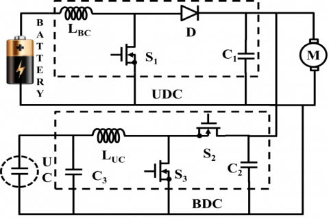
Figure 2. Converter model circuit diagram with HESS
Figure 2 represents that Converter model circuit diagram with HESS. Uni-directional converter and Bidirectional converters are designed with MOSFET switches, BDC will work in boost mode as well as buck mode and UDC works in only boost mode. Here the buck mode operation of a BDC can useful during charging of the UC. The two energy sources battery is connected to UDC side and UC connected at BDC side. During peak power and starting time UC reacts quickly and remain times battery supplies the power to the electric motor. During boost mode operation of BDC switch three in ON condition, during buck mode operation of BDC switch two is in ON condition. For the successful operation of UDC switch, one is in ON condition. In order to achieve preferable control of energy storage system overall circuit can be resolved into four subcircuits.
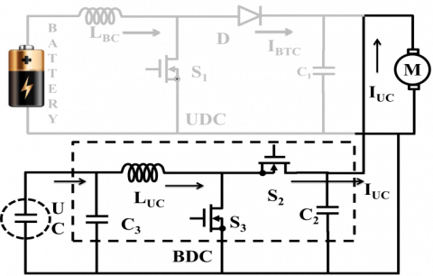
3.1. Mode-1 operation
Figure 3. Converter mode1 circuit diagram with HESS
In this mode of operation switch S3 only in ON condition remain switches S1, S2 are in OFF position. This mode is related to heavy load condition on the motor. The motor requires huge current during starting and heavy load condition, in order to meet the peak power requirement UC has been come in two the picture because UC can capable of meeting the high-power densities. Pulses have been generated to only BDC converter and there are no pulse signals generated to UDC converter. Here BDC works in boost mode to meet the peak power requirement which is connected to UC end and the power flows from UC to electric motor only.
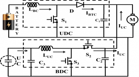
3.2. Mode-2 operation
Figure 4. Converter mode 2 circuit diagram with HESS
This mode is related to slightly heavy load condition on the motor. Battery and UC collectively meet the power required by the electric motor. Switches S1 and S3 are in ON position remain switch S1 is in OFF position. The pulse signals have been generated to both BDC and UDC. Here UDC always works a boost converter and BDC also works as a boost converter for this load only. The power flows from UC to electric motor and Battery to the electric motor. Here battery is connected to UDC one end and UC is connected to BDC one end.
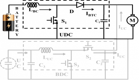
3.3. Mode-3 operation
Figure 5. Converter mode 3 circuit diagram with HESS
Mode-3 is related to normal load condition on the electric motor. During this mode of operation, the motor requires average power only no need of peak power requirement. Switch S1 is in ON position and remain switches S2, S3 are in OFF position. So entire power required to the motor can feed by the battery only. The pulses signals generated to only UDC and there no pulse signals generated to UDC.
3.4. Mode-4 operation
Figure 6. Converter mode 4 circuit diagram with HESS
Figure 6 represents the mode-4 operation of the circuit and during this condition switches S1, S2 are in ON position remain switch S3 is in OFF position. The power required to the motor and, for UC charging can be supplied by the battery only. In this mode of operation, the motor is working with no load, so the motor requires normal power only. That means during mode-4 UC is charging and BDC is working as a buck converter. The pulse signal has been generated to BDC as well as UDC also. So the power flows from the battery to UC as well as electric motor.
The battery and UC together supply the energy required to the electric motor in all conditions depending on the speed range of the motor. Here source switching can take place with the load changes on the electric motor. In this work, different types of loads have been taken in four modes like a heavy load, slightly greater than rated load, rated load and no load condition. During first mode of operation UC only supplies the demanded power of the motor, in second mode of operation UC and battery together supplies the power to motor, in third mode of operation battery only meets the required power of the motor and in fourth mode of operation battery can able to supply power to the motor as well as UC for charging. The entire circuit model operation can be performed in four modes.
Figure 7. Flowchart of the proposed control strategy
(1) In mode-1 of operation, a heavy load is applied due to which the speed of the motor is ≤4800rpm, during this situation motor requires more power which is more than that the base energy source capacity. The supporting source UC will supply the peak power by generating the pulse signals to BDC working as a boost converter, and MFB controller generates signal 1 for math function U1, 0 for remain three math functions.
(2) In mode-2, slightly more than rated load is applied due to which the speed of the motor maintained between 4600rpm to 4800rpm. And motor required slightly more than rated power, so base source and supporting source together supply power to the motor. The MFB controller generates pulses signal as 1 for both math functions U1, U2 and also generates a signal as 0 for remain two math functions. The BDC as well as UDC both are working under boost mode, in order to meet the load requirement
(3) A rated load is applied in mode-3 operation due to which the speed of an electric motor maintained between 4801rpm to 4930rpm. In this mode of operation battery only supply the load required by which initiates the operation of UDC as a boost converter and no pulse signals generated to BDC. The MFB controller generates pulse signals as 1 for only U3 and generates 0 for remain three math functions.
(4) Due to no load applied to the motor, the speed will maintain >4931rpm. In this mode, the battery supplies the power to load as well UC which initiates the operation of BDC as a buck converter and UDC as a boost converter. The MFB controller generates pulse signals as 1 for math function U4 and generates 0 for remain three math functions.
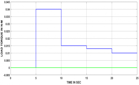
From the figures 8 and 9, it is clear that different loads have been applied to the motor at different time periods. At 5 to 10 sec heavy load applied to the motor, 10 to 15 sec slightly greater than the rated load applied, 10 to 15 sec normal load applied and 15 to 20sec light load applied to the electric motor. In the entire load conditions, the designed controller generated pulses to converters based on the speed of the motor for smooth switching between UC and battery. From the speed and armature current of an electric motor, the variation has been clearly observed from one load to another. During heavy load condition fluctuations in current and speed are more and these huge changes will decrease from heavy load to normal load. That means during no load condition there are no fluctuations in speed and current curves of the electric motor.
Figure 8. The load applied to the motor
Figure 9. Speed and current curve variations with respect to the load
Figure 10. Pulses generated by controllers to the unidirectional converter as well as a bidirectional converter
Figure 10 represent that pulses generated to BDC and UDC during all load condition on the electric motor. Up to 4 sec period, the electric motor is in the transient period, during this period UC and battery together supplying the power to the motor. At time period 5 sec heavy load applied and that will be continued up to 10 sec, during this period UC only supplies the energy to the motor. During the period 10 sec to 15 sec slightly greater than rated load, motor required energy can be supplied by the UC and battery. During the period 15 sec to 20 sec rated loads applied to the motor, required power can be supplied by the only battery. After 20 sec time period, no load applied to the motor, during this situation power flows from the motor as well as UC. Finally, during starting and heavy load condition energy can be supplied by the UC only, so in this time period, the pulse signals have given to BDC for boost mode. And during slightly greater than rated load condition UC and battery together supplies, so pulse signal has been generated to UDC as well as BDC. At the time of normal load applied on the motor battery only supplies energy, so pulse signals have been generated to only UDC. During no-load condition, UC is in charging mode, pulses have been generated to UDC as well as BDC.
Figure 11. Input voltage and current values of UDC
The input voltage and current of a Uni-directional converter also changing according to the switching between the UC and battery. Here UDC has been connected at battery end and it always works in boost mode only. The input voltage and current values always depend on the pulse signals generated by the controller. During the switching period of energy storage elements, a small disturbance also occurred.
Figure 12. Output voltage and current values of UDC
Figure 12 represents that output voltage and current values of the Uni-directional converter. The current profile of UDC is changing according to switching between the energy storage elements.
Figure 13. Input voltage and current values of BDC
The input voltage and current values of BDC change corresponding to a load on the motor. During heavy load condition, BDC will act a boost converter s similarly during no load condition BDC will act as a buck converter.
Figure 14. Output voltage and current values of BDC
Figure 14 represents that output voltage and the current value of BDC. The BDC has been connected at the UC end. BDC acts as a buck converter during charging period of UC similarly BDC acts as a boost converter during the discharging period of UC.
Table 1. DC-DC converters ON/OFF states based on the mode of operation
|
S.No |
Type of mode |
State of UDC |
State of BDC |
Power flow direction |
|
1 |
Mode-I |
Off |
Boost |
UC supply power to load |
|
2 |
Mode-II |
Boost |
Boost |
Battery and UC together supply power to Load |
|
3 |
Mode-III |
Boost |
Off |
Battery only supply power to load |
|
4 |
Mode-IV |
Boost |
Buck |
The batter can supply power to load as well as UC |
Table 2. MFB controller outputs corresponding to speed
|
S.No |
Speed condition associated with mode |
ON State Math Function |
|
1 |
If Speed is ≤4800 rpm |
U1=1&U2=0, U3=0, U4=0 |
|
2 |
If Speed is from 4600 rpm to 4800 rpm |
U1=1, U2=1& U3=0, U4=0, |
|
3 |
If Speed is from 4801 rpm to 4930 rpm |
U3=1 &U1=0, U2=0, U4=0 |
|
4 |
If Speed is >4931 rpm |
U4=1& U1=0, U2=0, U3=0 |
Hybrid energy supply system using a battery and UC as the energy storage components and BDC, UDC is used for controlling the energy distribution of these storage strategies are investigated and presented in this contribution. MFB controller has been designed and is implemented to switch the energy storage elements present in HESS for Hybrid electric vehicle/electric vehicle. The designed MFB controller combined with a conventional PD controller, generating the pulse signal to the bidirectional and unidirectional converts present in the system. Mainly the designed controller worked in four modes of the electric motor and for every mode contained separate math function. During mode 1 operation controller has been generated the pulses to BDC to supply energy to the motor from UC. In mode 2 operation controller have been generated pulses to UDC as well as BDC to supply energy to motor from UC and battery. During mode 3 operation controller have been generated pulses to only UDC to supply energy to motor from the battery. During mode 4 operation controller have been generated pulses to BDC as well as UDC to supply energy t motor and UC from the battery, which means during this mode UC gets charging. The proposed method contains low power electronic converters; this reduces the power losses and improves the lifespan of the battery. The simulation results have been verified with proposed methodology and with this attempt transient current production by battery have been prevented. The battery discharging and UC charging, discharging conditions modes could be switched smoothly based on the control strategy.
Averbukh M., Lineykin S., Kuperman A. (2015). Portable ultracapacitor-based power source for emergency starting of internal combustion engines. IEEE Transactions on Power Electronics, Vol. 30, No. 8, pp. 4283-4290. https://doi.org/10.1109/TPEL.2014.2355422
Genco A., Viggiano A., Magi V. (2018). How to enhance the energy efficiency of HVAC systems. Mathematical Modelling of Engineering Problems, Vol. 5, No. 3, pp. 153-160. https://doi.org/10.18280/mmep.050304
Horrein L., Bouscayrol A., Cheng Y., Dumand C. (2015). Hybrid energy management strategy for hybrid electric vehicle. 2015 IEEE Vehicle Power and Propulsion Conference (VPPC), Montreal, QC, pp. 1-6. https://doi.org/10.1109/VPPC.2015.7352963
Liu N., Chen Q., Lu X., Liu J., Zhang J. (2015). A charging strategy for PV-based battery switch stations considering service availability and self-consumption of PV energy. IEEE Trans. Industrial Electronics, Vol. 62, No. 8, pp. 4878-4889. https://doi.org/10.1109/TIE.2015.2404316
Lustenader E. L., Guess R. H., Richter E., Turnbull F. G. (2015). Development of a hybrid flywheel/battery drive system for electric vehicle applications. IEEE Transactions on Vehicular Technology, Vol. 26, No. 2, pp. 135-143. https://doi.org/10.1109/T-VT.1977.23670
Shen J., Khaligh A. (2016). Design and real-time controller implementation for a battery-ultracapacitor hybrid energy storage system. IEEE Transactions on Industrial Informatics, Vol. 12, No. 5, pp. 1910-1918. https://doi.org/10.1109/TII.2016.2575798
Tani A., Camara M. B., Dakyo B., Azzouz Y. (2013). DC/DC and DC/AC converters control for hybrid electric vehicles energy management-ultracapacitors and fuel cell. IEEE Transactions on Industrial Informatics, Vol. 9, No. 2, pp. 686-696. https://doi.org/10.1109/TII.2012.2225632
Wu D., Todd R., Forsyth A. J. (2015). Adaptive rate-limit control for energy storage systems. IEEE Transactions on Industrial Electronics, Vol. 62, No. 7, pp. 4231-4240. https://doi.org/10.1109/TIE.2014.2385043
Xiang C. L. (2015). A new topology and control strategy for a hybrid battery-ultracapacitor energy storage system. Energies, Vol. 7, No. 5, pp. 2874-2896. https://doi.org/10.3390/en7052874
Yin H., Zhou W., Li M., Ma C., Zhao C. (2016). An adaptive fuzzy logic-based energy management strategy on battery/ultracapacitor hybrid electric vehicles. IEEE Transactions on Transportation Electrification, Vol. 2, No. 3, pp. 300-311. https://doi.org/10.1109/TTE.2016.2552721
Zhang J. Shen T. (2015). Energy management strategy design for plug-in hybrid electric vehicles with continuation/GMRES algorithm. 2015 European Control Conference (ECC), Linz, pp. 2964-2969. https://doi.org/10.1109/ECC.2015.7330988