OPEN ACCESS
The wipers are an important part of the locomotive that affects the front view of the driver. Owing to the big initial load difference between the right and left sides, the wipers may not run synchronously and may interrupt the driver’s view, posing threats to driving safety. To solve the problem, this paper designs a synchronous controller suitable for dual arm wiper system. Relying on an MSP430F149 single-chip microcontroller (SCM), the proposed controller identifies the working states of the wipers by a Hall current sensor, and gives off digital signals via the I/O port of the SCM according to the working states. Isolated by the photoelectric coupler, the bus transceiver drives the relay after buffering, thereby achieving the synchronous movement of the wiper on both sides. Experiments show that the proposed controller can realize the synchronous control of the wipers in a stable, simple and low-cost manner. The research findings shed new light on wiper control and driving safety of locomotives.
dual motor drive, wiper, hall current sensor, synchronous control
The traditional single motor wiper is mainly composed of DC motor, reducer, connecting rod structure, wiper blade, wiper arm and other components. The structure is simple and easy to control. But there are some shortcomings: first, due to the physical characteristics of mechanical connecting rod, after using a long time, the clearance of the juncture of the wiper arm and the connecting rod may become larger due to abrasion, leading to instability. Second, the front windshield of the locomotive is large. Due to the layout limitations of the single motor drive, the brush area may be too small to ensure driving safety. Third, the mechanical link structure may occupy a lot of space, which is not easy to be installed. The double motor drive wiper better solves the above problems, which uses two DC permanent magnet motors to drive the wipers on each side. The wipers do not have mechanical connections, which greatly reduces the space and weight. It achieves the different wiping effect such as synchronous movement, and is widely adopted in the industry (He et al., 2008).
At present, research on wiper control of dual-motor driving mainly include the following aspects: the first is the design of the systematic mathematical model, namely to find mathematical model that accurately describe the actual operation characteristics of the wiper and get the tracking curves of the wiper movement; precisely; second is the design of the feedback controller, which can make the wiper move according to the desired trajectory planning, that is, to achieve the trajectory tracking of both wipers; Third, one wiper can adjust itself according to the trajectory tracking of the other wiper. In this way, accurate synchronization control of the wipers can be realized (Chen et al., 2013; Joon et al., 2006; Jean, 2009). However, the popularization of the dual-motor drive is limited due to the high cost, complex system and inconvenient maintenance. In addition to the new types of locomotives, such as high-speed rail and other new locomotives have been equipped with stepless speed control motor, a large number of locomotives such as DF_4 and 5, still use ordinary dual-motor drive wipers.
The difference of the parameters of the two DC motors of ordinary dual-motor drive wipers are great and the running speed is different, resulting in the differences in the swing speed of the wiper arms, which may interrupt the driver's field of vision and affect traffic safety. The synchronous control of the wiper used in this traditional locomotive can ensure the safety operation and reduce the cost of locomotive replacement, which has practical significance and practical value (Gao, 2017).
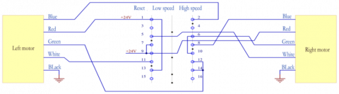
The wiper with ordinary dual-motor mainly consists of four parts: controller, transmission mechanism, wiper motor and wiper arm (Zheng et al., 2011; Zhang et al., 2011; Yin et al., 2011). The controller controls the working state of the motor. The motor rotates to drive the wiper arm through the transmission mechanism. The start, reversible conversion, speed control functions of the wiper are implemented by a universal switch of LW5D-16 series. The handle of this type of switch handle has 3 positions namely, 0°, 45° and 90°. When the handle is at 0°, the wiper is in "reset" state; when it is at 45°, the wiper is in "low-speed" state; When it is at 90°, the wiper is in "high-speed" state. The wiper motor speed regulation belongs to step speed regulation. The wiring mode of the switch is shown in figure1. The rated operational voltage is 24V. According to the wiper test requirements, wipers should be able to work under the voltage of 0.7U-1.25U, that is, between 16.8V to 30V. In general, the speed of the low-speed wiper should be no less than 20 times per minute, and the speed of the high-speed wiper is no less than 45 times per minute. The difference between low-speed and high-speed wiper should be no less than 15 beats per minute.
Figure 1. Wiring diagram of the switch
The scheme is to detect the wire current and reset it with analog switches. As shown in Figure 1, when the wiper switch turns to different stalls, the power line will change. The red line is always connected to the power supply. When the speed is low, the red line and the green line are connected to the power supply at the same time. When rotated to high-speed position, the red line and the blue line are connected to the power supply. Therefore, the wiper working at low speed and high-speed state, the current in green and blue line is different when the wiper works at different speed. According to the test results, when in the low-speed state, the current flows through the green line. When in high-speed state, the current mainly flows through the blue line. In the reset process, the current flows through the red line and green line. Therefore, the working state of the wiper can be judged by the change of the current parameters, and the reset state can be identified by the microcontroller, and the reset control can be implemented to realize synchronous control of the wiper on both sides.
The system consists of the detection part, the control part and the drive part. The detection part includes the current sensor and the arithmetic unit; the control part refers to the control unit with MCU as the core; the drive part includes the isolator and the power relay. In the detection part, the operational amplifier calculates and amplifies the current values collected by the current sensor, which will be sent to the control part after that. The control part calculates and analyzes the signal value of the sensor, and outputs the control quantity to the drive part according to different results. The driving part receives the signal of MCU, and controls the start and the close of the electric relay.
3.1. MCU minimum control unit
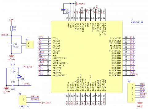
The system uses the microprocessor MSP430F149, The Minimum system control unit should include reset circuit, clock circuit and power supply part, as shown in figure 2. MSP430 uses a low level reset circuit composed of RC, and an 8MHz external passive oscillator as the master clock externally. In addition, the controller has serial port and simulation interface for testing. 3.2 current sensor circuit
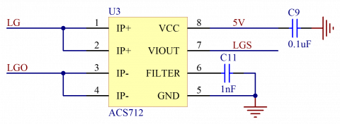
The system uses Holzer current sensor for current detection to improve accuracy, which also has isolation effect. Allegro’s Holzer current sensor ACS712 has a variety of models, which are different in current detection range including 5A, 20A and 30A. 5A detection range is used by the system (Zhang et al., 2011; Zhang et al., 2016; Zhang and Xu, 2011). The output voltage is calculated as follows:
$V_o=\frac{1}{2}V_{cc}+185mV\times I_P$ (1)
The application circuit of ACS712 current sensor is simple. IP+ and IP- are the input and output end of the current to be tested. FILTER is connected to 1nF capacitor as well as the ground. OUT pin is the analog signal output value. The typical application circuit is shown in figure 3. 3.3 Level matching operation circuit
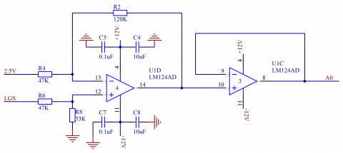
According to the formula of the output of Hall current sensor, when the current range is 0~5A, the output voltage is between 2.5V~3.425V. However, the internal ADC sampling range in MCU is 0~2.5V, the signal output by the sensor should be enlarged to adapt to the sampling range of ADC. According to the demand, the output value should minus 2.5V, and then magnified 2.7 times. In order to ensure the accuracy of the operation, the system uses the general four-way operational amplifier LM124 of TI and the voltage reference chip MCP1525 of Microchip to generate 2.5V reference voltage. The level matching operation circuit is shown in figure 4. The signal first goes into the subtracter, subtracting 2.5V and then being enlarged. The post level is accessed to voltage follower, and then the processed signal is sent to ADC pin.
Figure 2. MSP430F149 minimum system
Figure 3. ACS712 application circuit
Figure 4. Circuit diagram of level matching operation
3.2. Isolation and drive circuit
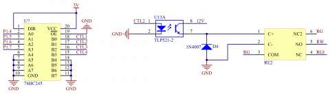
In the system, MCU needs to control large current equipment, so isolation between I/O and drive equipment is needed. The system adopts TLP521 photoelectric coupler of Toshiba Co. Due to the small current output of the optocoupler, the direct drive of the relay will lead to severe heat and low life expectancy. The system uses TI's 74HC245 bus transceiver with tristate output before the optocoupler to improve the drive capability (Zhang, 2014). Digital signals given by the I/O was buffered by 74HC245 and then go through the input end of the photoelectric coupler. When I/O outputs high-level current, 74HC245 outputs high-level current and the input end of photoelectric coupler turns on and the internal LED light is on. The output triode is connected, the relay coil is energized, the normally closed contact of the relay is disconnected and the normally open contact is connected. When I/O outputs low-level current, the result is the opposite. The circuit is shown in figure 5.
Figure 5. Circuit diagram of isolated drive module
The system software mainly includes: main program of system operation, filtering program of current acquisition software and state identification program.
4.1. System master program
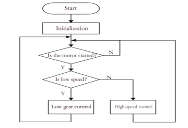
After the program starts, the modules are initialized at first. After the initialization, the ADC starts to collect the data of the sensor and determine the working state of the wiper. To prevent signal jitter which may lead to misjudgment, when the number of state accumulated exceeds the set value, the system can determine that the of wiper has entered into working condition, and then it enters the corresponding subroutine to execute corresponding control. After entering the subroutine, the MCU control relay to transfer the switch according to the specified time sequence, which controls the wiper to be reset once every cycle and starts at the same time in the next cycle. The flowchart of the main program is shown in figure 6.
4.2. Current acquisition software filtering
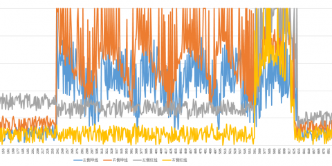
In order to ensure the sampling value of the current can reflect the working state of the wiper, the sampling value of the current and draw the original waveform of the green and red lines from the start to the end, as shown in figure 7.
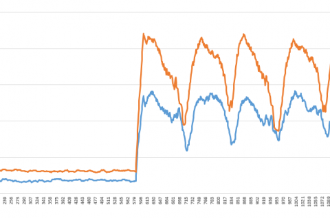
It can be found that due to the load of the wiper and unstable working current, much signal noise is produced. Therefore, 20-time recursive filtering algorithm is adopted (Bayindir et al., 2011; Ivens et al., 2013; Hu et al., 2016; Shabbir and Evangelou, 2014). By means of the 20 recursive mean filtering, the signal mutation can be effectively suppressed, and the waveform is more gentle. The waveform effect after using the average filter is shown in figure 8. Thus, after using the 20-time recursive mean filtering algorithm, the waveform has been greatly improved compared to the original waveform, which can be used as the reference data of state identification.
Figure 6. Flowchart of the main program
Figure 7. Waveform of the original current
Figure 8. Waveform of 20-time recursive mean filter
4.3. Current acquisition software filtering
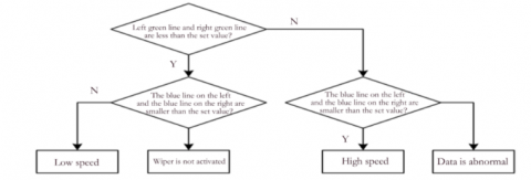
At the beginning of the program, the ADC module is initialized, and the values of each channel of ADC are read sequentially, and the mean filtering is carried out. Then, the flag bits of the corresponding states are accumulated by the values of each channel. The wiper gear identification process is shown in figure 9. After the values of the four channels are get, the first step is to determine whether the values of the left and right sides of the green line are greater than the set value; the second step is to determine the values of the left and right sides of the blue line are greater than the set value. If they are both less than the set value, the wiper is not started; if the value of the green line is greater than the set value, and that of the blue line is smaller than the set value, the wiper is in low-speed condition; if the value of the green line is less than the set value while the value of blue line is greater than the set value, then the wiper is in high-speed condition; if the values of the left and right sides of the green line and the blue line are greater than the set value, the sampling is wrong.
Figure 9. Flowchart of state identification
The debugging synchronization controller is installed on the wiper synchronous control experimental platform, and the rotating switch is rotated to low speed and high speed respectively to observe the working state of low-speed and high-speed conditions. The speeds of the wiper are different in the process of scraping, but there is a synchronous process in each control cycle. When the faster wiper arrived at the origin, it will wait for the slower side. After the two sides of the wipers are reset, the whole system will start again at the same time. The field operation process is shown in figure 10.
Figure 10. The operation result after debugging
5.1. Speed test
According to the requirements of the wiper, the low speed should be no less than 20 times per minute, and the speed of the high-speed wiper is no less than 45 times / min. The index was tested 10 times, and the test results are shown in table 1. The test shows that the average speed of the low speed gear is 25 times per minute after the synchronization control is added, and the average speed of the high speed gear is 45 times / minute, which can meet the requirements.
Table 1. Testing results of wiper speed
|
Serial number |
Low speed (times / minute) |
High speed (times / minute) |
|
1 |
24 |
45 |
|
2 |
25 |
45 |
|
3 |
24 |
46 |
|
4 |
24 |
45 |
|
5 |
25 |
44 |
|
6 |
25 |
46 |
|
7 |
25 |
45 |
|
8 |
25 |
45 |
|
9 |
24 |
45 |
|
10 |
25 |
45 |
|
Average value |
25 |
45 |
5.2. Stability test
Start the wiper and let it work for a long time to test the time when the controller can work stably. The test results are shown in table 2. According to the test results, when the controller is in low-speed and high speed, the wiper can work normally within 5 hours. According to the running state of the wiper, the working time has little influence on the stability of the wiper.
Table 2. testing results of stability
|
Serial No. |
Low Speed |
High Speed |
||||
|
2H |
3H |
5H |
2H |
3H |
5H |
|
|
1 |
√ |
√ |
√ |
√ |
√ |
√ |
|
2 |
√ |
√ |
√ |
√ |
√ |
√ |
|
3 |
√ |
√ |
√ |
√ |
√ |
√ |
|
4 |
√ |
√ |
√ |
√ |
√ |
√ |
|
5 |
√ |
√ |
√ |
√ |
√ |
√ |
Due to the difference of load between the left and right sides of the windscreen wiper of the DF_4 and 5 locomotives, the wiper cannot operate synchronously under the driving of both motors, which may interrupt driver's sight and affects the safety operation of the locomotive. In view of this problem, through the analysis of the operation mechanism of the two wipers, the synchronous control scheme of the wiper is drawn up, and the synchronous control system is designed. On this basis, the experimental platform is built and mechatronics control of the system is carried out. The experimental results show that the controller can realize synchronous control of the wipers, and the test results of the speed and the stability meet the requirements. The control effect is good, which can effectively solve the problem of asynchrony, and achieve the desired goal. The new controller has the advantages of high stability, simple operation, easy to maintenance, low cost and so on. In order to make the wiper controller adapt to more severe weather and complex environment, and ensure the safety of the locomotive, the adaptive wiper technology based on image processing has made great progress, which can automatically start and adjust the speed of the wiper according to the environmental changes. With the development of electronic, automatic and intelligent locomotives, the future wiper controller will also become more intelligent.
This article is supported by special research project of Shaanxi Provincial Department of education in 2018.
Bayindir K. C., Gozukucuk M. A., Teke A. (2011). A comprehensive overview of hybrid electric vehicle: Powertrain configurations, powertrain control techniques and electronic control units. Energy Conversion & Management, Vol. 50, No. 2, pp. 1305-1313. http://dx.doi.org/10.1016/j.enconman.2010.09.028
Chen W., Wu Y. F., Du R. H. (2013). Robust dynamic surface control for the servo system driven by two motors synchronously. Information and Control, Vol. 42, No. 5, pp. 625-631. http://dx.doi.org/10.3724/SP.J.1219.2013.00625
Gao Z. H. (2017). The driver’s steering feel assessment using EEG and emg signals. NeuroQuantology, Vol. 16, No. 2, pp. 6-13.
He L., Long Y. H., Teng J. I. (2008). Design of locomotive wiper controller based on PWM. Journal of Hunan University of Technology, Vol. 24, No. 6, pp. 84-88. http://dx.doi.org/10.3969/j.issn.1673-9833.2010.06.021
Hu J., Shao Y., Sun Z., Wang M., Bared J. (2016). Integrated optimal eco-driving on rolling terrain for hybrid electric vehicle with vehicle-infrastructure communication. Transportation Research Part C, Vol. 68, No. 8, pp. 228-244. http://dx.doi.org/10.1016/j.trc.2016.04.009
Ivens T., Spronkmans S., Rosca B., Wilkins S. (2013). Model-based eco-driving and integrated powertrain control for (hybrid) electric vehicles. Electric Vehicle Symposium & Exhibition, Vol. 6, No. 2, pp. 1-9. http://dx.doi.org/10.1109/EVS.2013.6914958
Jean L. (2009). Synchronization of a pair of independent windshield wipers. Analysis and Control of Nonlinear Systems, Vol. 12, pp. 225-242. http://dx.doi.org/10.1007/978-3-642-00839-9_11
Joon W. S., Seon B. L., Man H. K., Suk L., Chang L. (2006). Intelligent rain sensing and fuzzy wiper control algorithm for vision-based smart windshield wiper system. Journal of Mechanical Science and Technology, Vol. 20, No. 9, pp. 1418-1427. http://dx.doi.org/10.1007/BF02915965
Shabbir W., Evangelou S. A. (2014). Real-time control strategy to maximize hybrid electric vehicle powertrain efficiency. Applied Energy, Vol. 135C, pp. 512-522. http://dx.doi.org/10.1016/j.apenergy.2014.08.083
Yin A. D., Zhao H., Zhang H. (2011). A study on the control strategy for hybrid electric bus based on fuzzy control and particle swarm optimization. Automotive Engineering, Vol. 33, No. 7, pp. 553-553. http://dx.doi.org/10.1111/j.1365-2761.2010.01212.x
Zhang C. X., Xu W. M. (2011). An intelligent wiper controller based on fuzzy control theory. Computer Measurement & Control, Vol. 19, No. 2, pp. 309-311. http://dx.doi.org/10.1097/IGC.0b013e31820fa168
Zhang G. G. (2014). A review on hybrid vehicle powertrain matching and integrated control based on ECVT. Practical Applications of Intelligent Systems, Vol. 279, No. 9, pp. 1121-1128. http://dx.doi.org/10.1007/978-3-642-54927-4_107
Zhang S. P., Zhang Y. K., Wang Q. N., Zhang L. (2011). Ratio control strategy of continuously variable transmission for ramp-driving working condition. Journal of Jiangsu University, Vol. 313, pp. 273-277. http://dx.doi.org/10.3969/j.issn.1671-7775.2010.03.006
Zhang Y., Ma X., Yin C., Yuan S. (2016). Development and simulation of a type of four shaft ECVT for a hybrid electric vehicle. Energies, Vol. 9, No. 3, pp. 141.
Zhang Z., Chau K. T., Wang Z., Li W. L. (2011). Improvement of electromagnetic compatibility of motor drives using hybrid chaotic pulse width modulation. IEEE Transactions on Magnetics, Vol. 47, No. 10, pp. 4018-4021. http://dx.doi.org/10.1109/tmag.2011.2152371
Zheng C. H., Lim W. S., Cha S. W. (2011). Performance optimization of CVT for two- wheeled vehicles. International Journal of Automotive Technology, Vol. 12, No. 3, pp. 461-468. http://dx.doi.org/10.1007/s12239-011-0054-4