OPEN ACCESS
This paper attempts to design a stuiable circuit for electrohydraulic proportional amplifer. Firstly, the pulse width modulation (PWM) control principle of the amplifier was discussed, along with the recent development of the amplifier and the control requirements of proportional direction valve. Then, a mathematical model was established for the proportional solenoid coil current. On this basis, the author analyzed the control method of electrohydraulic proportional amplifier, and detailed the circuit design for the amplifier. The proposed design was then verified through a control test and software simulation. The test results agree well with the simulation data, indicating that the circuit design is feasible and valid.
pulse width modulation (PWM), proportional solenoid coil, proportional amplifier, simulation.
The proportional amplifier as an important element of the control system for the proportional solenoid valve serves to provide the proportional solenoid valve with specific current so that the flow or pressure it outputs is proportionally controlled (Canuto & Acuña-Bravo, 2013). The proportional amplifier developed with the state-of-the-art has many defects such as complicated structure design, unreasonable circuit board layout, poor heat dissipation of electronic components, inconvenient maintenance, and potential risks (Malaguti & Pregnolato, 2002; Wang et al., 2015). In order to resolve the technology mismatches of the above proportional amplifier, here comes a new type of proportional amplifier.
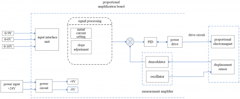
After input control signal is processed and amplified, the current signal is offered to the proportional electromagnet to control the electromagnet movement (the electromagnet drives the spool to move), and acquire the feedback signal of the displacement sensor to form a closed loop control on the electro-hydraulic proportional valve.
The input interface and the signal processing module work together to finish the following functions: 1) proportional processing performed on different standard signals, after amplifying, it outputs 0~6VDC control signal; 2) functions set with initial current affect the variation range of the nominal signal: -0.187~ 0.187V; 3) slope is adjusted for the step input signal, 0.03~5S; 4) level preset function filters out interference and improves stable output; the amplification module function is measured: 1) signal generator generates the sinusoidal excitation signal of 2.5KHZ and rectangular pulse demodulation signal; 2) the excitation signal is amplified to provide the displacement sensor with sufficient excitation current; 3) the inductive signal of the displacement sensor modulates the excitation signal; 4) phase sensitive detection and amplification adjustment; functions of PID regulator: 1) process the overshoot; 2) amplify gain adjustment; 3) add the control and feedback signals; 4) integral processing.
3.1. Composition
The proportional amplification board VT5001 (Jin et al., 2014; Zhao & Qiao, 2015) consists of power circuit, input interface unit, signal processing circuit, regulator, measurement amplifier, and power drive. The signal processing part includes two modules, i.e. initial current setting and slope adjustment; the measurement amplifier also includes two modules, i.e. oscillator and demodulator. The block diagram of the proportional amplifier is shown in Fig. 1.
Figure 1. Block diagram of proportional amplifier
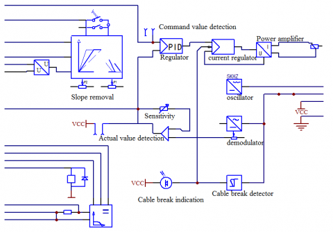
Figure 2. Functional block diagram
3.2. Working principle
The proportional amplifier control circuit mainly consists of input interface, signal processing circuit, regulator, pulse width modulation type power amplifier, measuring amplifier, fault monitor alarm, and power circuit. Its working principle is given as follows:
The external (0~9V) step control signal accesses to the signal processing circuit via the interface circuit, and the step signal is slope-modulated and sent to the regulator. The regulator has excitation oscillation and PID control function, and is excited by the displacement feedback signal for oscillation. Input control and displacement feedback signals are processed synthetically. Overall modulated oscillation control signal enters the pulse width modulation power amplification circuit for current amplification. At last, the drive electromagnet is output. The size of the control signal can change its oscillation frequency.
The displacement sensor (Van Varseveld & Bone, 1997) excitation source is finished by a sine wave oscillator of the amplifier board. In parallel, the actual measurement signal of the DC displacement is output via the demodulation circuit.
If the circuit that connects the electromagnet and the displacement sensor breaks or has poor contact during operation, the fault monitoring alarm will detect and give an alarm.
3.3. Power circuit
The power circuit consists of capacitor filter, series voltage stabilizer, and single-dual power inverter. The schematic circuit is shown in Fig. 3. The circuit input is 24VDC, the working voltage ranges in 19~35 VDC; the positive and negative 9VDc voltage source is output. The positive and negative voltage values are adjusted by the potentiometer P6. The diode and the fuse constitute fault and short circuit protection, and stable ±9VDC voltage can be output.
Figure 3. Power circuit
3.4. Input interface
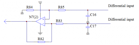
Input interfaces for two preset values, the one reference potential is 9VDC; the other is 6VDC. The instruction value is preselected to enable the function of the variable voltage, there is the preselection for internal and external instruction values; A differential input port with a differential op amp set inside takes charge of the input of control signals outside the amplifier board. The input interface circuit principle is shown in Fig. 4.
Figure 4. Input interface circuit
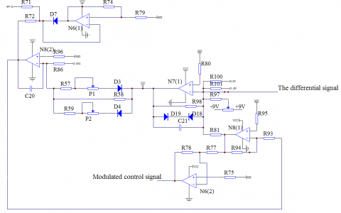
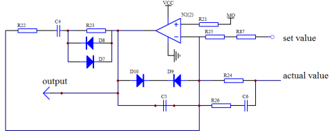
3.5. Signal treatment circuit
Figure 5. Signal treatment circuit
In this section, the slope treatment and initial current setting are included. The slope modulation is performed on the control signal to avoid abruption in the operation due to step change of the input control signal. The initial current setting is mainly used to generate the pre-excitation current of the proportional electromagnet, so that the proportional valve quickly starts up from the initial position when the set value is input.
The ramp generator converts the input step control signal into a ramp output signal. The rise and fall times can be adjusted by the potentiometers P1, P2, and the ramp time varies in the range of 0.03 s ~ 5 s. Potentiometer P5 is calibrated as initial current. The circuit schematic diagram is shown in Fig. 5.
Figure 6. Schematic diagram of regulator
3.6. Regulator
The regulator is a component of the electric feedback proportional amplifier. Its function is to improve the steady-state and dynamic quality of the feedback closed-loop control proportional valve; make the proportional valve reach a certain control precision; suppress the interference to boost the mobility.
There are multiple regulator circuits. The VT5001 amplifier board is designed as a comprehensive PID regulator. P mainly performs gain adjustment. The main output signal of I-differential adjustment grows linearly over time. D-integral regulator mainly responds to the changes of output signal with the input. It has good dynamic behavior and can eliminate control deviations in more common applications (Ahn & Yokota, 2005).
This circuit is also a voltage-frequency oscillation circuit. When the input DC signal changes in size, the sinusoidal oscillation frequency of the output changes with it.
The output signal of the ramp generator is transmitted as a preset signal to the PID regulator and integrated with the feedback (displacement) signal to form a closed loop control circuit. The schematic diagram of circuit is shown in Fig. 6.
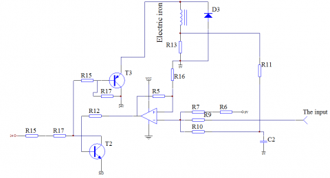
3.7. Pulse width modulation power amplifier circuit
Output voltage/current is adjusted by changing the pulse width. PID adjustment is transmitted to the input terminal of the pulse oscillator according to the set value and the actual deviation. Eventually, the current output by the power amplifier controls the electromagnet. Due to the inductance, the current on the coil becomes a DC signal of a small amplitude, charge-discharge superimposed AC signal, which acts as a flutter (eliminating the electromagnet friction and hysteresis), so that the pulse width modulation frequency is also the flutter frequency, no need to design a special flutter circuit (Cristofori & Vacca, 2010; Wang et al., 2014).
The circuit consists of op amp downstream hysteresis comparator and amplifier comprised of two triodes. Sinusoidal oscillation signal is converted into a rectangular wave with variable frequency via a downstream hysteresis comparator, which is current-amplified by a triode amplifier. Control the electromagnet operation by adjusting the output voltage/current by variable frequency. R11 acquires current negative feedback to achieve output short circuit overcurrent protection. The schematic diagram of circuit is shown in Fig. 7.
Figure 7. Pulse width modulation power amplification circuit
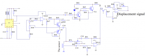
3.8. Measuring amplifier circuit
The measuring and amplifying circuit consists of oscillation circuit, demodulator circuit, and displacement sensor. The working process is: a sinusoidal signal of 2.5KHz frequency is generated by oscillator 8038, input into the primary coil of the displacement sensor, the displacement signal is output by the secondary induction coil, and the output amplitude is adjusted by the potentiometer P4. Since the output signal is alternating, the control circuit requires a DC signal, and the demodulation circuit converts the alternating signal into direct current signal. Adjust the sensitivity by the potentiometer P3, and sent the demodulated DC pulsation signal to the PID regulator circuit to form a closed loop control circuit with the set control signal.
The oscillation circuit is built using an 8038 function (Zheng, 2010). The demodulator circuit consists of discrete components such as field effect transistors, refer to the schematic diagram of circuit as below
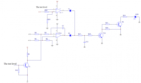
3.9. Fault monitoring alarm
Figure 8. Measuring amplifier circuit
Figure. 9 Fault alarm circuit diagram
The fault recognizer circuit detects the cables of electromagnet drive and the displacement sensor whenever possible. In the event of a breakage or overload, the level recognition circuit outputs an electrical signal to activate the LED alarm indicator. The circuit is composed of an op amp to form a level recognizer to complete the fault detection, and the triode and the LED indicator are used to form an alarm circuit. The schematic diagram of circuit is shown in Fig. 9.
4.1. Simulation for circuit characteristics
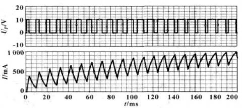
The parameters of the proportional electromagnet during simulation are: L=120mH. With the above parameters, the proportional amplifier is subjected to circuit simulation. The instantaneous characteristic curve of the switching tube input voltage US and the proportional electromagnet coil current I is shown in Fig. 10.
Figure 10. Transient characteristics of switching tube input voltage and coil current at the 8V input voltage
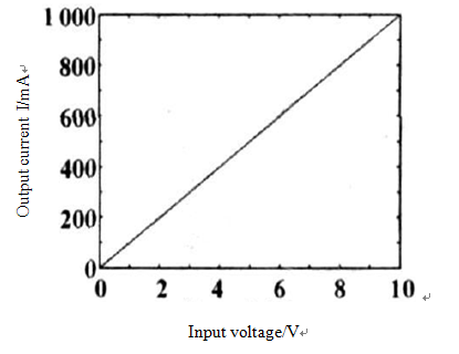
Figure 11. Curve of input voltage as a function of output current
As can be seen from Fig. 10, the output current is stabilized at 800 mA after about 0.16 s. Fig. 11 is a curve of the output current of the proportional amplifier as a function of the input voltage.
It can be seen from the curve, there is a strict linear relationship between the input voltage and the output current when the components work ideally
4.2. Experiment and output results
According to the above analysis, a PCB circuit board is fabricated for conducting an experiment which uses a proportional electromagnet GH263-045 (Xu et al., 2017) to obtain the coil output current for the load proportional electromagnet at different input voltages. Compare the experimental results with the ideal case, as shown in Table 1.
Table 1. Experimental results
|
input voltage Up/V |
Electromagnet coil simulates Current I/mA |
Electromagnet coil test Current IL/mA |
Error η% |
|
0 |
0 |
0.008 |
|
|
1 |
100 |
98 |
2 |
|
2 |
200 |
187 |
6.5 |
|
4 |
400 |
382 |
3 |
|
6 |
600 |
587 |
2.1 |
Note: error η=|I-IL|/I×100%
It can be seen from Table 1 that the linearity error of the proportional amplifier designed herein complies with the design requirements. The test results show that the amplifier has a high reliability and low power consumption, and can be completely used in practices.
The proportional amplifier is designed with the pulse width modulation technology. It consists of power circuit, signal processing circuit and circuit. Conducted the simulation and field test, it outputs results and linearity error basically consistent with the design requirements. The proportional amplifier features simple structure, high reliability, low power consumption, good regulation performance and disturbance rejection.
The author gratefully acknowledges the Science and Technology Program of the Education Department of China’s Shaanxi Province (No. 16JK1044), the Science and Technology Program of Baoji University of Arts and Sciences (No. YK1512) for the research grant.
Ahn K., Yokota S. (2005). Intelligent switching control of pneumatic actuator using on/off solenoid valves. Mechatronics, Vol. 15, No. 6, pp. 683-702. https://doi.org/10.1016/j.mechatronics.2005.01.001
Canuto E., Acuña-Bravo W. (2013). Hierarchical digital control of a proportional electro-hydraulic valve. Mechatronics and Automation (ICMA), 2013 IEEE International Conference on. https://doi.org/10.1109/ICMA.2013.6618054
Cristofori D., Vacca A. (2010). Analysis of the dynamics of a proportional valve operated by an electronic controller. 6th FPNI PhD Symposium. West Lafayette: FPNI Fluid Power Net Publications, pp. 199-214.
Jin B., Zhu Y., Li W. (2014). A differential control method for the proportional directional value. Journal of Zhejiang University (English Edition), Vol. 15, No. 10, pp. 892-902. https://doi.org/10.1631/jzus.C1400056
Malaguti F., Pregnolato E. (2002) Proportional control of on/off solenoid operated hydraulic valve by nonlinear robust controller. IEEE International Symposium on Industrial Electronics ISIE-02, Vol. 2, pp. 415-419. https://doi.org/10.1109/ISIE.2002.1026322
Van Varseveld R. B., Bone G. M. (1997). Accurate position control of a pneumatic actuator using on/off solenoid valves. IEEE/ASME Transactions on Mechatronics, Vol. 2, No. 3, pp. 195-204. https://doi.org/10.1109/3516.622972
Wang B., Shi G., Yu L. (2015). Modeling and analysis of the electro-hydraulic proportional value controlled motor system supplied by variable pressure accumulator. International Conference on Fluid Power and Mechatronics, pp. 1165-1170. https://doi.org/10.1109/FPM.2015.7337295
Wang H., Barker T., Chen K. (2014). Triaxial induction logging: Theory, modeling, inversion and interpretation. SPE International Oil & Gas Conference and Exhibition, Beijing, 2014, pp. 347-351. https://doi.org/10.2118/103897-MS
Xu B., Su Q., Zhang J. (2017). Analysis for drive circuit and improved current controller for proportional amplifier. Journal of Zhenjiang University (Engineering Science), Vol. 51, No. 4, pp. 800-806. https://doi.org/10.3785/j.issn.1008-973X.2017.04.022
Zhao L., Qiao Y. H. (2015). Design of weak signal detection system. Electronic Test, No. 20, pp. 1-3. https://doi.org/10.3969/j.issn.1000-8519.2015.20.002
Zheng Y. (2010). Digital amplifier for proportional directional valve with position feedback. Chinese Journal of Mechanical Engineering, Vol. 23, No. 1, pp. 60-65. https://doi.org/10.3901/CJME.2010.01.060