OPEN ACCESS
Consideirng the difference between virtual terminal charts for smart substations and the lack of specifications for virtual terminal addition and description, this paper attempts to develop a desriable method to check the consistency between the virtual terminals in secondary system of smart substations. For this purpose, a virtual terminal intelligent matching method was proposed through information standardization, that is, the virtual terminal information in substation configuration description (SCD) file are standardized according to the designations in vitual terminal charts. This method checks whether the virtual terminals are connected properly and corrects the errors quickly, laying the basis for automatic matching. The proposed method was verified through a case study. The results show that our method can improve the efficiency of virtual terminal verification in smart substations without sacrificing the accuracy of information matching.
standardization, smart substation, virtual terminal, match.
As China's strong smart grid construction advances in super express, smart substations based on the IEC 61850 standard have achieved dramatic development (IEC61850-6, 2004). As an important node in the smart grid, smart substation takes high-speed communication network as underlying infrastructure and enables information sharing and interoperability, improve the grid adaptability and control level, and satisfy users' demands for diversified, personalized, and interactive power supply services (Ferruzzi et al., 2014; Huang, 2015; Qiu et al., 2015).
In relay protection system for the traditional substation, the input and output for protection device correspond to actual terminals one by one, but in the smart substation, the networked optical fiber replaces the original point-to-point cable for connection, making the secondary circuit virtual, i.e. “invisible and untouched. This technological innovation has fundamentally changed the original maintenance and overhaul strategy for relay protection. Every time the equipment is replaced or rebuilt or expanded, technical personnel depend on the configuration tool to debug and check the SCD file and insure whether the virtual circuit is configured properly (Gao et al., 2015; Gao, 2014).
Currently, the design unit uses Excel file to store the information about virtual terminal for protection device as well designed. The manufacturer then configures Inputs information for each IED into SCD according to Excel files provided by the design institute. Due to differences in design style, language expression and format between design institutes, debuggers are often misled into design intents for configuration. Therefore, in order to make sure that the Excel information from the design unit matches the configuration information about virtual terminal in the manufacturer's SCD file, that is to say, to guarantee the virtual terminal configuration information in the SCD file implements the design intent of the design institute, we must inspect the consistency of the virtual terminal before the substation is put into service.
The SCD tools developed by various manufacturers are mainly used for configuration of their internal products (IEC6850-10, 2005). The existing configuration tools raise the bar for professional level and debugging experience of debuggers. The maintainers still examine the virtual circuit on the manual basis before the secondary system in Smart Substation is put into service. Take a 110kV smart substation as an example, there are about 5,000 virtual terminals in the SCD file. The workload of manual match is so heavy that it takes a long time and is prone to omission and misjudgments. The lack of effective automatic match tool will seriously affect the efficiency and progress of commissioning, operation and maintenance, and even endanger the safe and stable operation of relay protection systems (Cao et al., 2016). With the rapid growth of the smart substations, how to improve the work efficiency of the secondary operation and overhaul in smart substations is a great challenge those secondary system serviceman face now.
An effective way the above problems get resolved is to realize the integration of design and configuration, reduce the intermediate processes, in order that the design and the project configuration can be organically connected. However, according to the present situation, the design and configuration may not be seamlessly integrated in a short time. It is thus required that the O&M division should in-house design and develop a virtual circuit correlation consistency verification tool fit for its own needs, by which the original complex manual search is replaced by simple machine calculations, saving time and reducing the error rate.
At present, some auxiliary tools for managing smart substation SCDs have emerged on the site in order to track and trace back the profile version information. They also enable visualization management for configuration information via reduction of secondary terminal drawing layouts. These tools improve the management efficiency of the virtual circuit to a certain extent, but currently they are only used for the management work between SCDs or virtual terminal charts, unable to check the virtual loop association consistency between the SCD and the virtual terminal charts (Gao et al., 2014; Wang et al., 2010).
Aiming at defects such as lack of standardized data format and large mass of unavailable data in the virtual terminal chart, poor SCD readability, etc., this paper proposes a virtual terminal intelligence matching method in accordance with description standard: EXCEL is used as a general file format. The SCD is converted to an EXCEL document, the information in the virtual terminal chart is standardized, a mapping table is developed for device designation so that automatic match of the virtual terminals comes true.
This paper analyzes the virtual secondary circuit configuration information in smart substation, proposes the automatic verification method for SCD virtual terminal in accordance with the standard, and develops and designs a smart substation SCD virtual terminal match tool with certain universality, which can verify in a short period of time whether the virtual circuit is configured properly, improving the testing efficiency and the convenience of operation and maintenance of the smart substation.
At this stage, the secondary equipment in the substation is modeled in accordance with IEC 61850 which uses an object-oriented modeling method and defines a tree-shaped and hierarchical data model structure divided into physical devices (PD) and logical devices (LD) logical nodes (LN). data object (DO), data attribute (DA)from top to bottom. On this basis, a globally unique index generates for each object, namely, the data format of virtual terminal designation is ServerLD/LN$FC$DO$DA, manufacturer prefix + LD / LN $ function constraint $ DO $ DA.
The main function of the virtual terminal chart is to effectively express the virtual terminal association between different devices at different intervals in a smart substation. Some information contained are interval name, input name, input virtual terminal number, input virtual terminal name, input virtual terminal definition, input virtual terminal soft press plate setting, output name, output virtual terminal number, output virtual terminal name, output virtual terminal definition and output soft press plate setting, etc.
The virtual link information is saved in the virtual link node ExtRef under each LD Inputs of each IED, jointly expressed by six sub-items daName, doName, ldIns, lnClass, lnInst, and prefix.
From an application, in the pilot project of smart substations that have already been constructed, there are some problems in the expression of virtual terminals, as shown below:
There are a large number of secondary manufacturers in domestic market. They have any divergence of interpretation of the specifications so that the virtual terminals designed in accordance with the general specifications still have certain differences.
In the process, the designer uses the Chinese name to describe the name or definition of the virtual terminal in order to facilitate its own work. Due to the different expression habits and means in Chinese, many different terms ultimately represent the same device.
3.1. Data format and extraction
The virtual terminal chart is not a standard 2D data chart provided by the Design Institute. Due to the different view and operation habits of the designers, some cells are merged or span the columns, causing the irregular format inconvenient for data post-treatment on the computer. In addition, the virtual terminal chart lists all the virtual terminals for the transmitting side, but most of the virtual terminals that the receiver terminal is not configured are in an idle state, and do not constitute a complete virtual connection. When performing the consistency check, this part of the virtual terminal can be ignored.
According to the above analysis, before the virtual terminal consistency check, data in the original EXCEL file needs to be cleared up and extracted, and converted into the format that the computer can directly process. Three steps should be followed as below:
Standard format. Cancel the merged cells in the Device Name column, and populate data in the blank cells as required to restore it to a standard 2D data sheet.
Extract available data, traverse the whole virtual terminal chart document, determine and extract the data lines where the virtual terminals for receiver and sender sides all exist.
Data storage. Write the extracted available data in a new document for later use.
3.2. Device name mapping relation
Although the design institutes and manufacturers all follow the IEC 61850 standard and the Data Model of Protection Relay in Project Base on IEC 61850 in terms of virtual terminal configurations, there are divergences of interpretation of the specifications and there are many inconsistent expressions, for example, the design institute defines a virtual terminal chart by sending device name of "110kV 1# line intelligence unit A", while the corresponding Chinese description in the SCD reads the "191 Interval Intelligent Unit A", the former uses 110kV, 1#, line, the latter uses 191, interval, set, although two terms are equivalent, referring to the same device but causing expression inconsistency on both sides. In order to make a distinction between multiple IED devices in a substation, the Chinese name in the virtual terminal chart IED should be mapped into the IED instance name in the SCD.
The mapping relationship between the virtual terminal chart and the device name of the SCD is established, given that there are few secondary devices in the 110 kV Smart Substation, the manual matching strategy is used to manually map the IED name.
3.3. Auto match process of virtual terminals
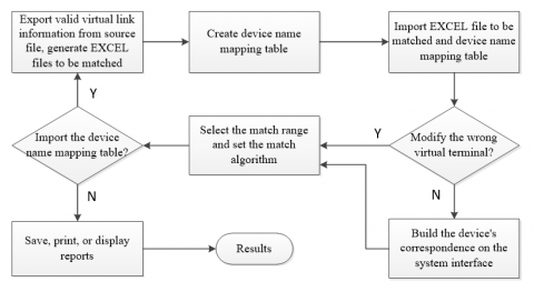
The auto match process of virtual terminals is shown in Fig. 1. The following describes the specific steps
Export the valid virtual link information from the virtual terminal chart and SCD to generate an EXCEL file to be compared, respectively.
A one-to-one correspondence is built between the names used to describe the one device in two files, and a mapping table of the virtual terminal chart and the device names in the SCD is also built.
Import the EXCEL files and mapping table of device name to be compared into the virtual terminal auto match system.
If the device mapping table is imported, go to the step (5) directly, otherwise, the device correspondence should be in turn established on the system interface.
Select the match range and set the match algorithm.
Generate and display the match result, based on which to determine whether the user needs to modify the wrong virtual connection in the source file. If yes, go to the step (1); otherwise, go to the step (7).
User chooses to save, print, display the report, or exit the system.
Figure 1. Flow chart of virtual terminal auto match
3.4. Architecture of virtual terminal auto match system
Based on the above analysis, the core of the virtual terminal auto match design lies in the user-defined interaction platform, which chooses the data column for matching virtual terminals as required in the work, establishes the mapping relationship of the device, and makes a choice of the algorithm and coverage to be matched.
3.5. System architecture and functions
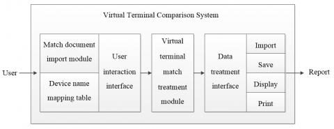
The architecture of user-defined virtual terminal match system is shown in Fig. 2. The system mainly consists of several modules such as the data import, user interaction interface, virtual terminal data treatment, and a data result output.
Figure 2. User-defined virtual terminal match system architecture
The user interaction interface module is mainly used for the user to set up the verification scope and the match algorithm. The user can customize the match scope at the interval of one or part or across the substation. There are two types of match algorithms for the user to choose, that is, one-way and two-way match. For one-way match algorithm, the calculation speed is faster, but the accuracy is lower; while for two-way match algorithm, the calculation speed is slower, but the accuracy is better. If no device mapping table is created in the previous period, after importing the virtual terminal file to be matched, an appropriate relationship may be manually added by dragging it and other operations according to the device names list displayed on the interface.
The virtual terminal data treatment module, on the one hand, acquires the user setting information from the user interaction interface based on which to calculate the source data; on the other hand, it interfaces to the data output module and transfers the match results from the virtual terminal data treatment module to the output module.
In the specific match procedure of the virtual terminal, the virtual terminal of the SCD is set as a standard item, and the virtual terminal in the virtual terminal chart is set as a reference item. First, according to a virtual connection device name in the standard item, the corresponding device in the SCD is found from the mapping table; then retrieve whether the device has data attribute with consistent expression, if yes, the data match is correct, and it is transferred from the general list into the correct connection list, and add 1 to the number of virtual terminals which are connected correctly; if not, this indicates that there is an error occurred during the configuration of the virtual connection, transfer it from the general list into the wrong connections list, and add 1 to the number of error connections in the virtual terminal.
The virtual terminal data output module displays "the number of virtual terminals connected correctly", "the number of virtual terminals connected wrongly" and "the virtual terminal connection error report", and the report file can be saved and printed out.
4.1. Experimental data
The virtual terminal data of several 110kV smart substations in Cangzhou are chosen for experimental analysis, and good debugging effect is obtained. Automatic match technology can effectively improve work efficiency and precision. In the past, manually verify the virtual circuit of a 110kV Smart Substation with virtual connections of around 4,000. An experienced engineer takes about 18 ~ 20 labor hours to complete this verification, and it is prone to omission and misjudgment. Now that the automatic match technology can finish the verification of the virtual connection consistency in the whole station within one hour, and the inconsistent and wrong connections can be clearly indicated through the output report.
4.2. Analysis of results
The tests are conducted on multiple smart substations for their virtual connection consistency check, and the following conclusions have been drawn by analyzing and summarizing the experimental results:
From the match accuracy, the calculation accuracy with the automatic match tool is above 98%.
From the work efficiency, the automatic match for virtual connections is performed by a computer, no need to cope with, search, etc. manually. As computer calculates the match results, it has an absolute advantage in time consumption.
From applicability, since data has been collated prior to matching, the data formats of the virtual terminal chart and the SCD document are standardized. A mapping method processes the Chinese device names with slightly different characters for description text of same device. the establishment of a name mapping table effectively avoid the divergences between the virtual terminal manufacturers. It can be compatible with most of the existing products of secondary manufacturers in domestic market.
For smart substations before completion acceptance and commissioning, the virtual terminal automatic verification method based on standardization is proposed against the problems existing in virtual terminal and loop correlation consistency verification work. With this method, the irregular format in virtual terminal chart is adjusted automatically. Only a mapping table that represents the correspondence between the virtual terminal chart and the device names in the SCD needs to be built to assist in the verification of the consistency for the virtual connections across the substation. The works of operators and inspectors can be transformed from the cumbersome repetitive mechanical labor in the past into the system optimization and data analysis, thereby improving the overhauling and debugging efficiency and quality. As this method runs based on data treatment specification, it is not restricted by specific design institutes or manufacturers, and well compatible with standards provided by different manufacturers and design institute. As above, it has a promising popularization and application prospect.
This paper was supported by Hebei provincial science and technology plan project self-raised funds (№16212106); 2017 national grid Cangzhou power supply company of science and technology project " the research of intelligent secondary circuit checking technology and security policy".
Cao H. O., Gao X., Yang Y. (2016). Analysis of online monitoring and intelligent diagnosis based on the full model SCD secondary system. Power System Protection and Control, Vol. 44., No. 14, pp. 136-141. http://dx.doi.org/10.7667/PSPC151348
Ferruzzi G., Rossi F., Bracale A. (2017). Bidding strategy of a micro grid for the day-ahead energy and spinning reserve markets: the problem formulation. International Journal of Heat and Technology, Vol. 35, No. S1, pp. S466-S471. http://dx.doi.org/10.1016/S0142-0615(01)00038-2
Gao X. (2014). Discusion on application technology of smat substation. Distribution & Utilization, No. 2, pp. 54-59. http://dx.doi.org/10.3969/j.issn.1006-6357.2014.02.009
Gao X., Yang Y. J., Jiang J. N. (2014). Analysis of secondary circuit monitoring methods based on SCD. Power System Protection and Control, Vol. 42, No. 15, pp. 149-154.
Gao Z. Y., Yao J. G., Guo K. Y. (2015). Study on the supporting role of smart grid to the construction of smart city. Power System Protection and Control, Vol. 43, No. 11, pp. 148-153.
Huang Y. Z. (2015). Smart substation is the further objective of SAS. Power System Protection and Control, Vol. 41, No. 22, pp. 88-92.
IEC61850-10 (2005). Communication networks and systems in substations: Part 10 basic communication structure for substations and feeder equipment: conformance testing[S].[S.l.]:IEC.
IEC61850-6 (2004). Communication networks and systems in substations: part 6 configuration description language for communi-cation in electrical substations related to IEDs[S].[S.l.]: IEC.
Qiu W. M., Guo D. W., Zhang C. Y., Xu Y. X., Wang G. (2015). A smart grid client-side testing platform for monitoring. Mathematical Modelling of Engineering Problems, Vol. 2, No. 3, pp. 17-20. http://dx.doi.org/10.18280/mmep.020305
Wang F., Fang C. E., Li W. (2010). Design of substation configuration tool based on IEC61850 standards. Power System Protection and Control, Vol. 38, No. 10, pp. 106-109. http://dx.doi.org/10.3969/j.issn.1674-3415.2010.10.023