OPEN ACCESS
A promising process that can meet the growing needs to develop new sources of energy and respond to new environmental legislations is power generation using waste heat sources in Organic Rankine Cycle (ORC). In this study, selection of five pure working fluids have been investigated for the maximal net power output, safety and environmental aspect under different ORC configurations. Superheating has a negative impact on the thermal efficiency for all working fluids. ORC with an internal heat exchanger (IHE) and Isopentane as working fluid shows a significant improve on performance and the thermal efficiency achieves 13.16%, this value is higher than the thermal efficiency of Baseline ORC and ORC with superheating by 1.4 % and 1.38 %, respectively. The use of IHE plays an important role in increasing thermal efficiency and keeping a maximal net power.
organic Rankine cycle, internal heat exchanger, working fluid, superheating, waste heat source
Rising prices of fossil and recently apprehension to their disappearance, seeks to reduce their environmental impacts are creating a renewed interest to explore novels mechanisms for rational use of heat sources. An encouraging process that accomplishes this objective is power production exploiting waste heat sources in ORC. ORC offers the advantage of power production from low-grade thermal energy sources such as industry wasted heat and thermal power plants. Likewise, renewable energies can be also used in ORC instead of conventional sources.
Through time, researchers continue to investigate the power generation in ORC from various sources of heat. Recently, from waste heat recovery (Dong et al., 2012), biomass power plants (Liu et al., 2011), geothermal power plants (Imran et al., 2016) and solar thermal power plants (Tzivanidis et al., 2016). The ORC cycle is characterized by the use of an organic fluid as an alternative to water. The utilization of low and medium temperature heat is a complicated task, in which several aspects must be taken into account such as environmental impacts and thermo-physical properties of candidate fluids in order to select the optimal choice. Hung et al. (2010) tested eleven organic fluids in the ORC cycle. They found that isentropic organic fluids are more appropriate to recovery low grade temperature waste heat. Maizza et al. (2001) examined the thermodynamic and physical properties of some unconventional fluids for use in ORC, they suggested that low liquid specific heat, high latent heat and high density fluids promote absorption of thermal energy in the evaporator. Therefore, reduces the needed flow rate and the pump consumption. Vaja et al. (2010) performed parametric analyses on internal combustion engine (ICE) bonded to an ORC in order to: firstly, determine ideal evaporating pressures of R11, R134a and Benzene, and secondly calculate the maximum efficiencies of several cycle configurations. The results exhibited that an increase of 12% in overall efficiency could be achieved compared to that found by the unaccompanied ICE. Mago et al. (2008) studied regenerative ORCs using dry fluids (R113, R123, R245ca and isobutene) to transform waste heat to power from low grade thermal heat sources. The study shows that regenerative ORC reduces the needed amount of heat to generate the same power compared to the basic ORC.
As conclusion, from the most cited works, an additional work is needed, which is studying, at once time, the effect of the combination between heat source conditions, nature of working fluids and cycle configurations on performance of ORC cycle.
Thus, the objective of the current work is to investigate effectiveness of various schemes of ORCs to recover waste heat of medium flow rate and low-grade temperature of exhaust gas (typically recuperated from of a tailpipe of an installation of cogeneration) and thereafter indicate the best couple (fluid-configuration), where five working fluids are used in three ORC configurations. The adopted criteria to achieve this goal are the net power output and thermal efficiency.
The different configurations considered in the present study are Basic Organic Rankine Cycle, ORC with superheating and ORC with IHE respectively.
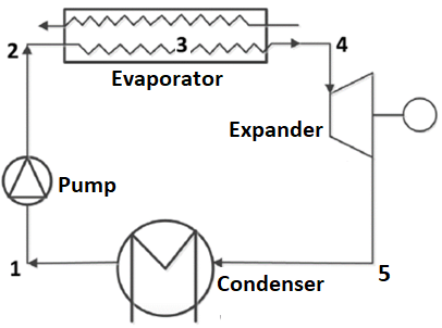
A basic ORC configuration for recovering waste heat is shown in Figure 1(a), which is consisted from four component, a pump facing an expander and evaporator facing a condenser. The working fluid is first pumped from a condenser at a low pressure to high pressures entering into evaporator. Notice that, the entropy stays constant throughout the pumping process in an ideal cycle. Thermal energy is absorbed, at constant pressure from a heat source, by the liquid entering the evaporator. During this process, a phase change occurs in the organic fluid from a saturated liquid to a saturated vapour. The produced high-pressure vapour passes into the expander where its thermal energy is transformed to a work.
(a) Basic ORC system
(b) ORC with superheating
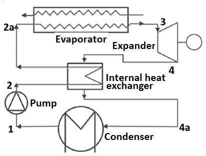
(c) ORC with IHE
Figure 1. Diagrams of different ORCs
The expander drives a generator. Therefore, an electrical energy is generated simultaneously. The vapour leaves the expander and before is condensed by a cooling water at the condenser, the organic fluid is then subjected to a phase change from a saturated vapour to saturated liquid. Subsequently, the pump drives back the condensed fluid to the evaporator and a new cycle begins.
Figure 1(b) presents the second conception considered in this study, which is the ORC with superheating. In this configuration, a super-heater is inserted between the evaporator and the turbine. The last conception considered in this study is an ORC cycle with IHE. The IHE is placed after the turbine exit and before the evaporator as shown in Figure 1(c).
2.1. Assumptions
In a real cycle, some losses happen in the expander and pump throughout the expansion and pumping phases. Hence, the pump and expander isentropic efficiencies are less than 100 %. The heat addition and rejection in the real process are not isobaric and the piping system is always vulnerable to pressure loss. In addition, the succeeding assumptions are adopted for modelling the ORC configurations:
Steady-state condition will be considered in all process of the cycles. Heat and friction losses are neglected as well as kinetic and potential energies. The pressure drops in the heat exchangers, condensers and associated pipelines are neglected. Furthermore, some ORC cycle characteristics considered in the present study are listed in Table 1.
Table 1. ORC conditions
|
Parameters |
Unit |
Values |
|
Environment pressure |
MPa |
0.1013 |
|
Environment temperature |
°C |
20 |
|
Maximal pressure |
MPa |
2.5 |
|
Condensation temperature |
°C |
30 |
|
Condenser pinch temperature |
°C |
8 |
|
Evaporator pinch temperature |
°C |
8 |
|
Pump isentropic efficiency |
% |
80 |
|
Turbine isentropic efficiency |
% |
85 |
|
Sink media |
- |
water |
|
Heat sink inlet pressure |
MPa |
0.2 |
|
Heat sink inlet temperature |
°C |
15 |
|
Mass flow rate of exhaust gas |
(kg/s) |
50 |
|
Temperature of exhaust gas |
°C |
160 |
2.2. Mathematical model and theoretical analysis.
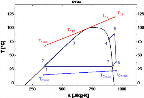
Figure 2 shows the thermodynamic representation of Rankine cycle in which there are four different processes:
Figure 2. Diagram (T-S) of Basic ORC
The saturated liquid quits the condenser before it is pumped to the evaporator. The specific pump power is defined by:
$W _ { p u m p } = \frac { \dot { m } _ { w f } \left( h _ { 2 s } - h _ { 1 } \right) } { \eta _ { p u m p } } = \dot { m } _ { w f } \left( h _ { 2 } - h _ { 1 } \right)$ (1)
$\eta _ { p u n p } = \frac { h _ { 2 s } - h _ { 1 } } { h _ { 2 } - h _ { 1 } }$ (2)
Where h2s denotes the isentropic enthalpy of working fluids when being compressed in the pump, h1 and h2 are, respectively, enthalpies at inlet and outlet of the pump.
$\dot { m } _ { w f }$ denotes the mass flow rate and $\eta _ { \text {pump } }$ the pump isentropic efficiency.
Point 4 indicates the evaporator exit when heat is absorbed by the working fluid. Hence, this process can be treated as isobaric transformation even though the small pressure drop in the evaporator tubing. We can calculate the heat absorbed by the working fluid using the following equation:
$Q _ { E } = \dot { m } _ { w f } \left( h _ { 4 } - h _ { 2 } \right)$ (3)
$Q _ { h } = \dot { m } _ { h } \cdot \overline { C p } _ { h } \left( T _ { h , i n } - T _ { h , o u t } \right)$ (4)
h4 is the vapour enthalpy at evaporator outlet and $\overline { C p } _ { h }$ represents the average specific heat capacity of the heat source, Th,in: inlet temperatures and Th,out: outlet temperatures
Thus, we can calculate the mass flow rate of the working fluid by:
$\dot { m } _ { w f } = \frac { \dot { m } _ { h } \cdot \overline { C p } _ { h } \left( T _ { h , i n } - T _ { h , o u t } \right) } { h _ { 4 } - h _ { 2 } }$ (5)
In this process, a useful mechanical work can be produced from the absorbed energy of the working fluid when it passes through the expander. The enthalpy drop (the expander power) is calculated by:
$W _ { T } = m _ { v f } \left( h _ { 4 } - h _ { 5 s } \right) \cdot \eta _ { T } = \dot{m} _ { w f } \left( h _ { 4 } - h _ { 5 } \right)$ (6)
Where h5 and h5s represents real and isentropic enthalpies of the exhaust organic vapour at the expander outlet, respectively and $\eta _T$ represents the isentropic efficiency of expander.
In this process, the condenser rejects the heat to the cooling water in order to condensate the working fluid and thereafter it recirculated in the cycle. Regardless of friction losses in the condenser pipes, the heat rejection is supposed to be isobaric even there is still a pressure drop in the condenser.
The working fluid becomes saturated after leaving the condenser. The rejected heat can be expressed by the following equation:
$Q _ { C } = \dot{m} _ { w f } \left( h _ { 5 } - h _ { 1 } \right)$ (7)
$Q _ { C w } = \dot { m } _ { C w } \cdot \overline { C p } _ { C w } \left( T _ { C w , o u t } - T _ { C w , i n } \right)$ (8)
Where $T _ { C w , i n } , T _ { C w , o u t }$, are defined as the temperatures of inlet and outlet, respectively, and $\overline { C p } _ { c w }$ represents the average specific heat capacity of the cooling water. Therefore, the mass flow rate of the cooling water can be calculated by:
$\dot { m } _ { C _ { v } } = \frac { \dot { m } _ { \mathrm { rf } } \cdot \left( h _ { 5 } - h _ { 1 } \right) } { \overline { C p } _ { C w } \left( T _ { C _ { w } , \text {out} } - T _ { C _ { w , i n } } \right) }$ (9)
For the whole system, the total net power produced by the ORC is:
$W _ { n e t } = W _ { T } - W _ { p u m }$ (10)
The thermal efficiency of the cycle is calculated by:
$\eta _ { t h } = \frac { W _ { n e t } } { Q _ { E } } = \frac { W _ { T } - W _ { p u m p } } { \dot { m } _ { w f } \left( h _ { 4 } - h _ { 2 } \right) }$ (11)
2.3. Organic Rankine cycle design
2.3.1. Basic organic Rankine cycle
It consists of the four basic transformations, which were already discussed. In basic ORC, the evaporator is divided into two units: the single phase liquid unit (preheating) and two phase liquid + vapour unit (evaporating). Each unit is conceived under the adopted conditions using the log mean temperature difference method (LMTD).
$\Delta T _ { L M D } = \frac { \Delta T _ { \max } - \Delta T _ { \min } } { \ln \frac { \Delta T _ { \max } } { \Delta T _ { \min } } }$ (12)
The total heat rate injected can be also written as:
$Q _ { E } = U A _ { E } \Delta T _ { L M T D }$ (13)
$\Delta T _ { m a x } , \Delta T _ { m i n }$ represents the maximal and minimal temperature differences at the ends of the exchangers, respectively, while UA represents the global heat transfer coefficient and heat transfer area and $\Delta T _ { LMTD} $ the logarithmic mean temperature difference.
The total heat transfer area of heat exchangers in the ORC can be approximately estimated by the total heat transfer capacity UAtot, which can be calculated by the next equations:
$U A _ { t o t } = \frac { Q _ { E } } { \Delta T _ { L M T D , E } } + \frac { Q _ { C } } { \Delta T _ { L M T D , C } }$ (14)
2.3.2. ORC with superheating
The T-S ORC with superheating is presented in figure 3. This ORC model differs from the first one by the superheating that takes place after the end of the evaporation.
Figure 3. Diagram (T-S) of ORC with superheating
In this conception, the evaporator is composed from three units for preheating, evaporating and superheating the organic fluid. As presented in the previous configuration, each unit is designed considering the operational conditions and using the LMTD.
2.3.3. ORC with IHE
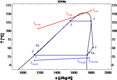
Figure 4 presents the T-s diagram for ORC cycle with IHE. This cycle uses an IHE to recover more heat. The working fluid exhausted from the expander at high temperature is driven to the low-pressure side inlet of IHE.
The working fluid leaving the pump at low temperature is conducted to an IHE. Therefore, part of the remaining heat in the working fluid, after it leaves the expander, is communicated to the working fluid of the new cycle.
Since in the IHE, heat and pressure loss are not taken into account. The heat transfer in IHE can be expressed as:
$Q _ { I H E } = \dot { m } _ { w f } \left( h _ { 4 } - h _ { 4 a } \right) = \dot { m } _ { w f } \left( h _ { 2 a } - h _ { 2 } \right)$ (15)
IHE effectiveness is the quotient of actual received energy of working fluid to its maximum possible value:
$\varepsilon = \frac { T _ { 4 } - T _ { 4 a } } { T _ { 4 } - T _ { 2 } }$ (16)
Figure 4. Diagram (T-S) of ORC with IHE
2.3.4. Pinch point
Pinch point temperature can be defined as the difference between the two values of the temperature of heat source and evaporator temperature. If the temperature of the heat source is supposed to be fixed, high pinch point results to a reduced evaporator temperature. According to a thermodynamic approach, the lower the pinch point, the higher the heat recovery and the overall plant efficiency, but the higher heat exchanger area and cost as well.
In this work, the pinch point will be in state 3. The pinch point in the condenser will be in state 6, it can be calculated by the following equations:
$\Delta T _ { p p , E } = T _ { h , p p } - T _ { 3 }$ (17)
$\Delta T _ { p p , C } = T _ { 3 } - T _ { C w , p p }$ (18)
2.4. Working fluid candidates
A selection of five working fluids with null ODP (ozone depletion potential) and a low GWP (global warming potential) were investigated using the thermodynamic model. Physical and corresponding environment specifications of the candidate fluids are presented in Table 2.
Table 2. Physical data and environmental data of candidate fluids for ORC (Guo et al., 2011; Rayegan et al., 2011)
|
|
Physical data |
Environmental data |
|||
|
M [kg/kmol] |
Tcr [°c] |
Pcr [MPa] |
GWP (100 yr) |
ODP |
|
|
Isopentane |
72.15 |
187.2 |
3.370 |
5 |
0 |
|
N-pentane |
72.15 |
196.5 |
3.364 |
5 |
0 |
|
Cyclohexane |
84.16 |
280.5 |
4.075 |
~ 20 |
0 |
|
N-hexane |
86.17 |
234.7 |
3.058 |
~ 20 |
0 |
|
Toluene |
92.14 |
318.6 |
4.126 |
~ 20 |
0 |
Aiming to validate the model presented above we resolved the energy balance equation under the same operating conditions of Saleh et al. (2007) where calculations combined the ORC with the thermal source.
Table 3. Validation of the model
|
Parameter |
Saleh et al. (2007) |
Present work |
Relative difference (%) |
|
|
Given |
T3 (°c) |
100 |
100 |
|
|
∆Tp (°c) |
10 |
10 |
||
|
T6 (°c) |
30 |
30 |
||
|
Wnet (MW) |
1 |
1 |
||
|
Th.in (°c) |
120 |
120 |
||
|
Calculated |
mwf (kg/s) |
33.424 |
34.265 |
2.52 |
|
T5 (°c) |
50.70 |
50.31 |
0.77 |
|
|
$\eta_{th}$ (%) |
12.52 |
12.50 |
0.16 |
|
The heat was transported by hot water and the evaporator inlet temperature was 120 °C. Isentropic efficiencies of pump and expander were 0.65 and 0.85, respectively, a value of 10 °C was taken for the pinch point temperature. The obtained results and those reported by Saleh et al. (Saleh et al., 2007) is shown in Table 3. It can be perceived that there is a good agreement between results of the two calculations in a sufficient accuracy for most engineering applications.
4.1. Basic organic rankine cycle
Figures 5 and 6 present respectively, net power output maximums of basic ORCs and their corresponding thermal efficiencies of the five organic fluid considered in this work.
Figure 5. Net power output maximums of basic ORCs with different organic fluids
Despite that the higher thermal efficiency is obtained for Toluene, we can see that there are a barely difference between the thermal efficiency of all considered working fluids. The difference between the higher and the lower value of the thermal efficiency is about 4%. Besides, greater net power output signifies that more power could be gained with the same operating heat source. Net power output maximums are contingent to the working fluid nature as shown in Figure 6. It is observed that the Isopentane has the highest net power output among the organic fluids, while Toluene shows the lowest net power output, even though it shows the highest thermal efficiency.
Figure 6. Thermal efficiencies of different organic fluids corresponding to the maximum net power output
Among the five considered organic fluids, the critical temperature of Isopentane (187.2 °C) is the closest to the waste heat temperature (160 °C). Hence, it can be concluded that the higher net power production will be yielded when the fluid critical temperature comes near to the waste heat source temperature.
Figure 7 illustrates the total heat transfer capacities of the heat exchangers (evaporator and condenser) in ORCs configurations in the case that at the maximums of net power outputs for the five different organic fluids.
Figure 7. Total heat transfer capacities with different organic fluids
Isopentane has the highest total heat transfer capacity among the candidate fluids, while Toluene presents the lowest total heat transfer capacity. Generally, greater value of UA indicates an extra cost of the heat exchanger.
Considering both criteria of net power and thermal efficiency, we conclude that Isopentane is the best choice among the working fluids list. Which can be affirmed by the absolute nature of net power output criterion, while that the thermal efficiency criterion gives a middle approach between the net power output and the quantity of heat extract from an already waste heat.
4.2. Organic Rankine cycle with superheating
This configuration has been widely adopted to improve the cycle efficiency. The superheater re-heats the working fluid generated by the evaporator, increasing its thermal energy and reducing the likelihood that it will condense.
4.2.1. Effect of superheating on ORC with superheating
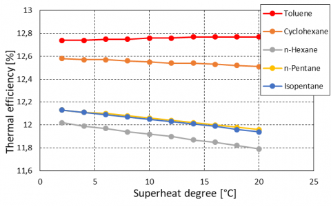
In such configuration, it’s commonly to study the performance of the cycle in terms of the superheat degree. Figure 8 shows the superheat effect on the thermal efficiency for five working fluids.
Figure 8. Effect of superheat on thermal efficiency
As may be seen, the thermal efficiency of Cyclohexane and Toluene is almost kept constant, but it decreases slightly for the other fluids. The result outlines that superheating is not necessary for these working fluids as they leaves the expander exit at a superheated state.
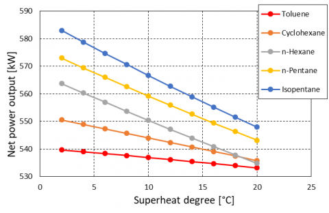
Figure 9. Variation of net power output with various superheat degree.
Figures 9 shows the net power output varying with various superheat degree of different working fluids. It is clear that an increasing in the superheat degree, will decrease the net power output. However, the higher turbine inlet-temperature does not always imply a greater turbine power output.
4.3. Organic Rankine cycle with IHE
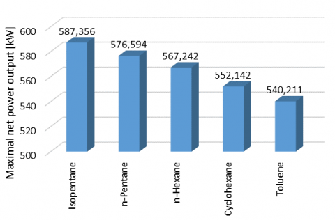
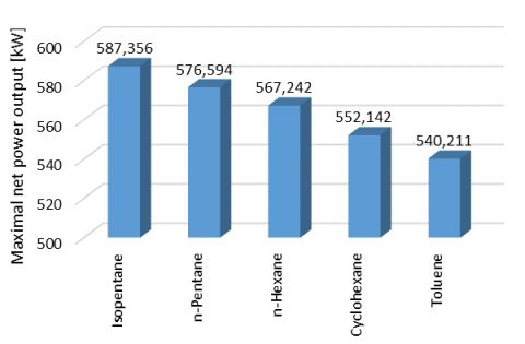
Figure 10. The maximal net power output of ORC with different working fluids
Figure 10 presents the maximal values of the net power output of ORC for five working fluids in the Organic Rankine cycle with IHE. The results show that using IHE does not bring any change on the net power output if compared to the basic ORC. In summaries, the net power output of Isopentane come first before all others working fluids (with a value equal to 587.356 kW), while the Toluene fluid represents the minimal net power output.
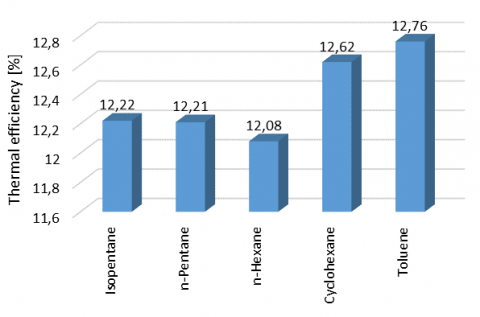
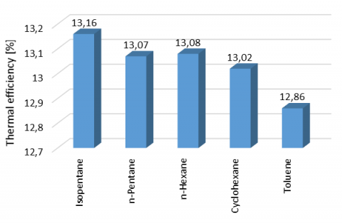
Figure 11. Thermal efficiency of different working fluids corresponding to the maximum net power output
Figure 11 presents the thermal efficiency of the different working fluids corresponding to the maximum net power output.
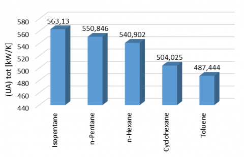
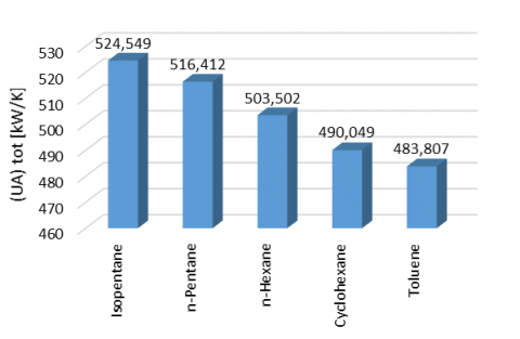
Figure 12. The total heat transfer capacity of the system with different working fluids
When comparing the maximum
value given by every single fluid, contrary to the previous ORC configurations, the better thermal efficiency is obtained by the Isopentane working fluid. In addition, the difference between the minimal and the maximal values of the thermal efficiency is about 2% for each fluid, which is less than that calculated in the preceding ORC cycles. This criterion allows us to conclude that all investigated fluids favourites theirs use in this type of ORC cycle.Figure 12 illustrates the complete heat transfer capacity of the evaporator and condenser in ORCs configurations, where the maximum net power output is considered with the five working fluids. The total heat transfer capacity might change from 483.807 kW/K to 524.549 kW/K. Isopentane has the highest capacity among the working fluids, while Toluene presents the lowest total heat transfer capacity.
4.4. Comparison between different cycles
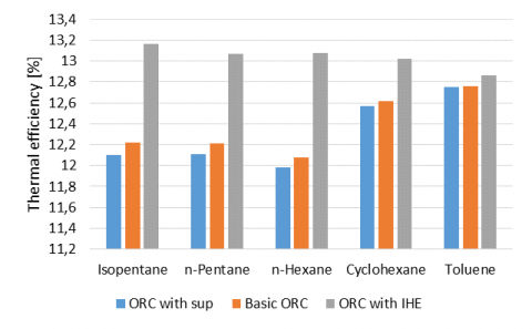
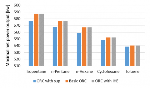
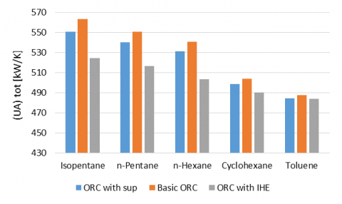
In Figures 13 (a-d), all the system characteristics (thermal efficiency, net power output and the total heat transfer capacity) for different designs (basic ORC, superheat of 5 °C and IHE) are reordered in the form of histogram in order to facilitate the comparison.
(a) Thermal efficiency of ORC cycles
(b) The maximal net power output
(c) The total heat transfer capacity
Figure 13. Comparison of different ORC schemes
Given the superheated state of the working fluid at the outlet of the expander, a substantial quantity of energy might be recovered from vapour at expander outlet and transformed to inward fluid. When the liquid leaves the pump, the recuperator increases its temperature and then the working fluid heats up before entering the evaporator. In this process the wasted thermal energy rejected by the condenser would be extracted and supplied again to the working fluid in the instant that when it leaves the pump. Therefore, the rejected heat by the condenser reduces.
Figures 13 (b) shows maximal net power output for the three different cycles. It is obvious that for the ORC with superheat the maximal net power output is less than the other two cycles.
Since, the coefficient of the total heat transfer signifies the total resistance to heat transfer corresponding to a fluid to another. Compared to basic configuration, the UA parameter is always reduced when resorting to a superheater or IHE that improve the performance of such configuration, in the same time, it is also accompanied by an increase/decrease on thermal efficiency corresponding to ORC-IHE/ ORC-Superheat respectively.
It is clearly remarkable that the couple (ORC IHE-Isopentane) presents the optimal configuration, which gives the better performance with varying thermal efficiency and net power output.
The couple (Design-Fluid) choice for the Organic Rankine Cycle is of a paramount importance and is very dependent on the heat source conditions, as well on the criteria to be considered.
In this study, a thermodynamic model for assessment of ORC waste heat recovery has been developed. Three ORC configurations where in each one a selection of five working fluids (with respect for environmental and safety standards) are tested. Therefore, in total fifteen arrangements were examined in order to get the optimal case. It should be noted that each configuration is characterized by two criteria; the net power output and the thermal efficiency.
According to results given by the model and regarding environment, safety and performance criteria, the following statements can be formulated:
Maximums net power output are remarkably related to the working fluid but they are less sensitive to ORC configuration. While for the thermal efficiency criterion, it varies noticeably using an internal heat exchanger, nevertheless an exception for the toluene where it varies slightly from a configuration to another.
Result show that the superheating is not required for this selection of organic fluids as they already quit the expander at a superheated state.
Results also revealed that the use of IHE does not bring any change on the net power output, but it gives a suitable gain on the thermal efficiency e.g. a relative gain of 7.7% with the use of IHE compared to basic ORC for Isopentane.
Depending on the currently working conditions (low temperature-range and medium mass flow rate of exhaust gas) the most appropriate couple ORC design-working fluid can be suggested as ORC with IHE- Isopentane.
|
$overline{C_p}$ |
average specific heat capacity (kJ/kg.k) |
|
h |
Enthalpy (J/kg) |
|
$dot{m}$ |
mass flow rate (kg/s) |
|
P |
pressure (MPa) |
|
Q |
the heat rate injected and rejected (kW) |
|
T |
temperature (K) |
|
UAtot |
the total heat transfer capacity (kW/K) |
|
∆Tpp,E |
the pinch temperature difference in evaporator (K) |
|
∆Tpp,C |
the pinch temperature difference in condenser (K) |
|
W |
power output (kW) |
|
Greek symbols |
|
|
∆T |
temperature difference (K) |
|
η |
efficiency (%) |
|
ηT |
isentropic efficiency of the expander |
|
ηpump |
isentropic efficiency of the pump |
|
µ |
dynamic viscosity, kg. m-1.s-1 |
|
Subscripts |
|
|
1-7 |
states in the cycle |
|
2s,4s |
stat points for the ideal case |
|
C |
condenser |
|
cr |
critical |
|
Cw |
Cooling water |
|
E |
evaporator |
|
hot |
hot source |
|
In |
inlet |
|
LMID |
logarithmic mean temperature difference |
|
net |
net |
|
out |
outlet |
|
pump |
pump |
|
T |
turbine |
|
th |
thermal |
|
tot |
total |
|
wf |
working fluid |
Guo T., Wang H. X., Zhang S. J. (2011). Fluids and parameters optimization for a novel cogeneration system driven by low-temperature geothermal sources. Energy, Vol. 36, No. 5, pp. 2639-2649. https://doi.org/10.1016/j.energy.2011.02.005
Hung T. C., Wang S. K., Kuo C. H., Pei B. S., Tsai K. F. (2010). A study of organic working fluids on system efficiency of an ORC using low-grad energy sources. Energy, Vol. 35, No. 3, pp. 1403-1411. https://doi.org/10.1016/j.energy.2009.11.025
Imran M., Usman M., Park B., Yang Y. (2016). Comparative assessment of Organic Rankine Cycle integration for low temperature geothermal heat source applications. Energy, Vol. 102, pp. 473-490. https://doi.org/10.1016/j.energy.2016.02.119
Liu H., Shao Y., Li J. (2011). A biomass-fired micro-scale CHP system with organic Rankine cycle (ORC)–Thermodynamic modelling studies. Biomass Bioenergy, Vol. 35, No. 9, pp. 3985-3994. https://doi.org/10.1016/j.biombioe.2011.06.025
Mago P. J., Chamra L. M., Srinivasan K., Somayaji C. (2008). An examination of regenerative organic Rankine cycles using dry fluids. Applied Thermal Engineering, Vol. 28, No. 8-9, pp. 998-1007. https://doi.org/10.1016/j.applthermaleng.2007.06.025
Maizza V., Maizza A. (2001). Unconventional working fluids in Organic Rankine Cycle for waste energy recovery systems. Applied Thermal Engineering, Vol. 21, No 3, pp. 381-390. https://doi.org/10.1016/S1359-4311(00)00044-2
Rayegan R., Tao Y. X. (2011). A procedure to select working fluids for Solar Organic Rankine Cycles (ORCs). Renewable Energy, Vol. 36, No. 2, pp. 659-670. https://doi.org/10.1016/j.renene.2010.07.010
Saleh B., Koglbauer G., Wendland M., Fischer J. (2007). Working fluids for low temperature organic Rankine cycles. Energy, Vol. 32, No. 7, pp. 1210-1221. https://doi.org/10.1016/j.energy.2006.07.001
Tzivanidis C., Bellos E., Antonopoulos K. A. (2016). Energetic and financial investigation of a stand-alone solar-thermal Organic Rankine Cycle power plant. Energy Conversion and Management, Vol. 126, pp. 421-433. https://doi.org/10.1016/j.enconman.2016.08.033
Vaja I., Gambarotta A. (2010). Internal combustion engine (ICE) bottoming with organic Rankine cycles (ORCs). Energy, Vol. 35, No. 2, pp. 1084-1093. https://doi.org/10.1016/j.energy.2009.06.001
Yang D., Ma Z. (2012). Conceptual design and performance analysis of waste heat recovery system for intelligent marine diesel engines. Part 1: Impractical analysis of traditional WHR systems. International Journal of Heat and Technology, Vol. 30, No. 2, pp. 85-92. https://doi.org/10.18280/ijht.300212