OPEN ACCESS
This research work presents a reliable technique to protect the stator winding of asynchronous machine. The protection scheme depends on continuous temperature monitoring of the winding. It utilizes integration between the DC injection method and an artificial intelligence technique. The soft starter coupled to asynchronous machine is used to inject DC signal. It modifies the operation of the reverse-parallel thyristors. The gate control signal of the soft starter produces a short delay in half current cycle for one phase of the machine. Then the DC components are obtained from the current and voltage Fourier analysis. By using the magnitude of the DC signals, the stator winding resistance and temperature are computed. To obtain an accurate temperature of winding; the calculated motor parameters are employed to be an input data for a fuzzy scheme. Therefore, the Adaptive Neuro-Fuzzy Inference System (ANFIS) scheme is utilized to supply an efficient and active temperature display for stator winding. In addition ANFIS decreased the estimation error of the winding temperature without affecting on motor torque at certain delay angle. The obtained results with Matlab simulation are inventively.
temperature estimation, thermal protection, adaptive neuro-fuzzy inference system, induction motor, signal injection, soft starter
The online monitoring of asynchronous machine temperature is essential in industrial processes. They are the most vastly used rotary machines in the industrial sector with ninety percentages (Hussein et al., 2016). The insulation of the winding is commonly the most failure component due to thermal overload. The extended period of thermal aging leads to stator insulation failures (Wahsh et al., 2016). The impairment losses of the insulation quality are a function of temperature and time according to Equation (1) (Fitzgerald et al., 2003). The deterioration rate can be represented as an exponential. The life-temperature relation illustrates that the failure time of organic insulation is halved for each 8 to 10°C rise.
life=AeB/T (1)
Where A and B are constants and T is the absolute temperature.
In the recent industries, many techniques are employed to monitor the thermal state of the asynchronous machine (Hubert et al., 2003). They aim to protect the machine from thermal overload cases (Pugachev et Fedyaeva, 2015). Some of these techniques utilize the thermal model for temperature estimation (Venkataraman et al., 2005). They increase their temperature accuracy by using higher thermal models. The transients of short time thermal overload are simulated by Boglietti et al. (2014). Boglietti et al. (2014) utilizes 1st order thermal model to predict the stator winding temperature of operative motor. Hurst et al. (1997) presented a thermal model with 2nd order and mad the offline experiments, in order to identify the specified parameters by installing thermal sensors. The thermal sensors record the temperature of the windings of the stator and rotor. To precisely calculate the temperature of the motor in different parts, a thermal network model using higher order lumped parameters is illustrated by Mellor et al. (1991). It is observed by Pugachev (2016) that the accuracy cannot be guaranteed due to the calculations of thermal parameters from the motor dimensions. Instead of a network with lumped thermal, an approach is proposed by Zhang (2015). The approach depends on transfer-function for reduction of the order of asynchronous machine thermal models. The main drawbacks of these thermal model-dependent procedures are the calculations of the thermal parameters. Especially they are not constant. In addition the measurement must be completed for each machine at different cooling states (Baneira et al., 2016).
Alternatively method is that utilizes machine parameters to compute the machine temperature. The asynchronous machine parameter-based techniques are constructed to estimate the temperature of the winding from the value of winding resistance (Lu et al., 2008; Matić et al., 2015). A method is adapted by Karanayil et al. (2003) to measure machine winding resistance using asynchronous machine model that depends on its equivalent circuit. This technique simply measures three quantities input voltage, input current, and speed of the rotor to display the resistance of machine windings. The equivalent-circuit-dependent techniques can comply with variations in conditions of cooling. But they are too sensitive to the variations of machine parameter. To exceed these troubles, it is presented by Wu and Gao (2006) to appreciate the resistance of the stator and rotor by injecting alternated current signal. The alternated current signal is attuned at proper frequency for inverter-fed machine applications. Alternatively manner is proposed by Lee et al. (2001) using DC signal. A DC bias is created in the feeding supply voltage. It uses the DC components of the injected current and voltage to compute the stator resistance. The temperature estimation of the windings from DC injection via the soft starter-fed machine is proposed by Zhang et al. (2008). It is more practical method for thermal protection, only lack for accuracy (Zhang et al., 2009). Therefore Zhang et al. (2009) propose an experimental setup to use a filter of adaptive Kalman. Its scheme decreases the temperature estimation error of motor winding, however, stay need more researches for reducing temperature estimation error.
This work presents a dependable technique to protect stator winding by means of continuous temperature monitoring of stator windings. The combination between the DC injection method and the artificial intelligence technique is achieved.
The research work is prearranged as follows. Section 1 is introduction, next the using of the soft starter to inject a nonintrusive DC signal is depicted in section 2. Section 3 discusses the influence of utilizing ANFIS with DC signal injection and displays ANFIS results; in addition different input sets to ANFIS Scheme are presented in Section 4. A comparison between the result of thermal monitoring using ANFIS and other technique results is displayed in Section 5. Finally, conclusion with short discussion is drawn in Section 6.
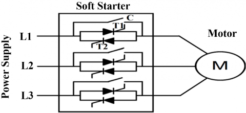
During motor acceleration, the soft starter enhances the starting performance of asynchronous motors. It controls voltage, current and torque. Typically, the soft starter controls voltage via reverse-parallel-coupled thyristors as shown in Figure 1. At the starting, thyristor gradually is turned on until it approaches full speed. The contacts (C) are closed when thyristors are fully on. After starting phase, soft starter becomes inoperative. Sometimes soft starter enters in the “bypass” mode when the contacts (C) are closed. This paper shows that the soft starter can be operative in the steady state operation of the asynchronous motors. It is used to monitor the temperature that generated in the motor stator at the steady state operation. To monitor the motor temperature, the soft starter injects DC signal to compute the resistance of the stator winding of machine; then the stator temperature is computed.
Now, this section illustrates how DC bias could be injected in the line voltages and currents of the machine stator during motor operation. The soft starter doesn’t inject continuously DC signal, because the temperature generated in the motor doesn't change simultaneously. Therefore soft starter goes in Temperature Monitoring Mod (
Figure 1. Basic structure of soft-starter with anti-parallel thyristors
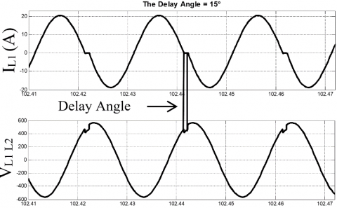
Figure 2. Motor line voltage VL1L2 and Phase current iL1 during TMM
During TMM duration, only one contact (C) of phase L1 is held in reserve open, while the supplementary two contacts remain closed such as bypass mode operation. At the same time a small delay is performed in the gate signal controller of one thyristor, e.g. thyristor (T2). Thyristor (T2) is appropriated to backward conducting of phase L1 after current of phase L1 falling the zero crossing. Hence the current and voltage waveforms become slightly not pure sinusoidal of the phase L1 at the TMM interval. Typical waveforms of machine phase current (iL1) and line voltage (vL1L2) are displayed in Figure 2, while a short delay angle δ is added, for example (δ =15°). The magnitude of the DC components is computed using Fourier analysis for voltage and current wave forms. After the
Fourier analysis is executed for the input current i(t) and voltage v(t) signals over one cycle window of the waves. The DC components are used to facilitate the calculation, because the DC equivalent circuit of asynchronous motor is employed. The Fourier analysis is used to calculate only the DC component of the current and voltage signal. Hence, the Fourier transform is the most suitable tool in this process. The other techniques such as wavelet give more details in frequency components. This details not required in this process. In addition they complicate the calculation.
The current wave i(t) can be expressed by a Fourier series of the following form as shown in Equation (2)( Gao et al., 2011):
$i ( t ) = \frac { a _ { 0 } } { 2 } + \sum _ { n = 1 } ^ { \infty } a _ { n } \cos ( n w t ) + b _ { n } \sin ( n w t )$ (2)
Where w is the angular fundamental frequency, a0 is the DC component and bn, an are the sine and cosine components respectively of Fourier coefficients for the n-th harmonic component. These coefficients can be written as Equations (3), (4) and (5):
$a _ { 0 } = \frac { 2 } { T } + \int _ { t - T } ^ { t } f ( t ) d t$ (3)
$a _ { n } = \frac { 2 } { T } + \int _ { t - T } ^ { t } f ( t ) \cos ( n w t ) d t$ (4)
$b _ { n } = \frac { 2 } { T } + \int _ { t - T } ^ { t } f ( t ) \sin ( n w t ) d t$ (5)
Where T=1/f1, f1: Fundamental frequency,
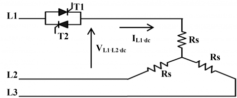
The DC components of voltages and currents haven’t influence on the motor rotor circuit, as the air gap prevents them from pass through it. Therefore the DC equivalent circuit of the asynchronous motor becomes only three connected resistances of the stator. Consequently it is respectable at the
Using the DC component of current and voltage in the motor terminals, the Resistance of the Stator (Rs) of the motor can be estimated as displayed in Equation (6) (Enany et al., 2013):
$R _ { s , d c } = 2 / 3 * \frac { v _ { L _1 L_2 } ^ { d c } } { i _ { L 1 } ^ { d c } } = \frac { 2 . v _ { t h } ^ { d c } } { 3 . i _ { L 1 } ^ { d c } }$ (6)
Where $v _ { L 1 L 2 } ^ { d c } , v _ { t h } ^ { d c }$ and $i _ { L 1 } ^ { d c }$ are the DC components of the motor line voltage $v _ { L 1 L 2 }$, Voltage across the soft starter and phase current iL1 respectively.
Equation 6 for asynchronous motor that its stator winding in star connection. Once the stator resistance is estimated from DC signals, the Temperature of the Stator (Ts) can be computed also according to the linearly proportional between the resistance and the temperature of the motor winding as presented in Equation (7) (Enany et al., 2014):
$R _ { s , d c } = R _ { s 0 } \left( 1 + \alpha \left( T _ { s , d c } - T _ { s 0 } \right) \right)$ (7)
Where:
Rs,dc the estimated stator winding resistance from DC injection
Rs0, the stator winding resistance at reference temperature T0
Ts,dc, the estimated stator winding temperature from DC injection
Ts0, stator winding room temperature
$\alpha$, The temperature coefficient (=0.0039K-1 for copper).
Figure 3. DC equivalent circuit of asynchronous motor at TMM
Using Equation 7, the computed stator winding temperature from DC injection can be directly calculated. An asynchronous motor with nominal power of ten hours power is used to test the proposed technique. Its nominal data is displayed in the appendix. The motor is connected with a three-phase balanced voltage source of 400V, 50 Hz. An entrenched perfect temperature sensor from Simscape™ is used to display the average temperature of the motor stator winding. It illustrated by Enany et al. (2014) that, the accuracy of the estimated temperature becomes better with longer delay angle. Nonetheless, the torque pulsation produced in motor by the delay angle rises as delay angle growths. The torque pulsation is rise because the voltage and current waves become not pure sinusoidal of the phase L1 at the TMM interval. Consequently, determining delay angle bargains with increasing temperature accuracy and torque pulsation.
The torque pulsation at
THD of Torque $= \frac { \sqrt { \Sigma _ { 1 } ^ { \infty } T _ { n } ^ { 2 } } } { T _ { F } }$ (8)
Where Tn value of the harmonics n in Torque TF value of the fundamental in Torque.
The effect of delay angle on the output torque of the motor is checked, at different delay angles during TMM interval. To illustrate the previous effect, the thermal monitoring scheme is simulated in Matlab Simulink. It utilizes a thermal resistor block from the Matlab Simscape™ software for validation purpose. Table 1 shows percentage of pulsation in the motor torque according to Equation 8 at different delay angles.
It displays also the average estimation error. The average estimation error is the difference between the estimated temperature using signal injection and measured temperature using Simscape sensor. The maximal delay angle value can be tuned online to limit the torque pulsation produced in asynchronous machine to be under an acceptable level at TMM interval. The maximal delay angle is assumed δ=15°.
Table 1. The effect of the delay angle on the estimated temperature and the output torque
|
δ in degree |
5° |
10° |
15° |
20° |
30° |
|
0.277 (ms) |
0.555 (ms) |
0.833 (ms) |
1.11 (ms) |
1.666 (ms) |
|
|
Estimation Error (°C) |
1.5 |
0.4 |
0.25 |
0.1 |
0.5 |
|
Torque pulsation (%) |
2.6 |
5.6 |
9 |
12.8 |
24.8 |
Note that the estimated temperature of the stator winding Ts,dc is computed from the estimated resistance of stator winding Rs,dc. The Rs,dc is estimated from DC injection method. It is obvious that, there is error in the estimated resistance of the stator winding. The noise in the voltage and current signals produces error in the temperature estimation. Hence the estimated temperature of stator winding has low accuracy. Therefore the following section illustrates how to increase the estimation accuracy.
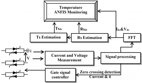
The artificial intelligent algorithms need a simple and less intensive mathematical design. An effective modeling or control is obtained of a highly non-linear system with a lot of uncertainties (Kamel et al., 2012). This paper utilizes ANFIS to increase the accuracy of the estimated stator winding temperature. The increase of the accuracy should be achieved without affecting motor torque. At the certain delay angle, the using of the fuzzy logic approach is tested to compute the temperature of the stator winding. Figure 4 illustrates the stator temperature estimation scheme with ANFIS. The gate signal controller is adjusted to produce a short delay angle equal to 15°. The delay angle is presented in operation for the backward thyristor in phase L1 at the TMM interval.
3.1. On-line training of ANFIS architecture
The first case of the input data to the ANFIS adaptive unit is Irms and Tdc. There are 32550 training data. The sampling frequency equals 500 HZ. It is a suitable sampling frequency value due to fsample>2forginal. The construction of the ANFIS architecture is built as follow. It has two neurons in the input layer (one for Irms and the other for Tdc) i.e. N=2, then three gbell Membership Functions (MF) designed for each input i.e. M=3 and the output is linear membership function.
3.2. Simulation results of thermal monitoring using ANFIS
The subsection appraises the performance of the proposed ANFIS scheme. A distinct test set was prepared covering different loading conditions for motor operation.
Figure 4. Stator temperature estimation scheme with ANFIS
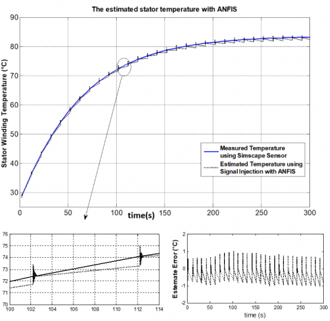
3.2.1. Full load testing
The asynchronous machine is loaded with 49.73 N.M corresponding to motor full load. The results are displayed as follow. Figure 5 displays the estimated stator temperature (Ts) based on DC injection using ANFIS with first case scheme. In addition, it contains the stator winding temperature displayed by the entrenched perfect temperature sensor. Figure 5 contains the two readings, to check the accuracy of the estimated temperature. It is obviously that the temperature of the stator winding computed with ANFIS agrees with that measured by entrenched perfect temperature sensor. As well, figure 5 displays the estimated error. The estimated error is the difference between the estimated temperature of the stator winding using ANFIS and entrenched perfect temperature sensor. As shown in figure 5, the estimated error of the stator winding temperature is 1°C at delay angle of 15°. This error appears when the winding temperature varies from 25°C to 85°C. Therefore a remote temperature monitoring and protection scheme becomes more practicable for winding of asynchronous motor.
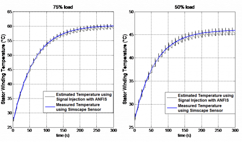
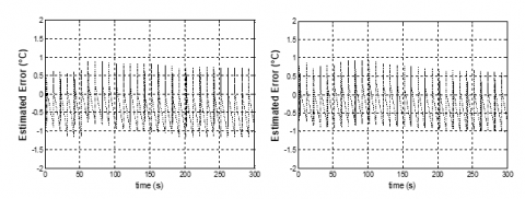
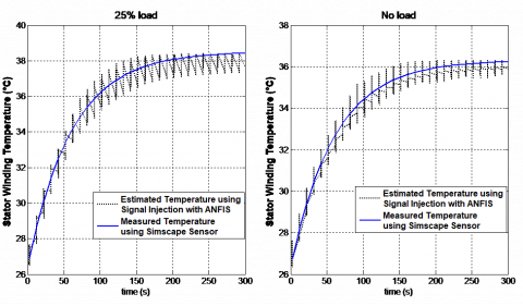
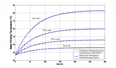
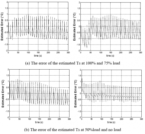
3.2.2. Various loading conditions testing
The performance of this technique is evaluated under many loading conditions in this part. The asynchronous motor is loaded with 0%, 25%, 50% and 75% of the rated motor load. The simulation results of each various loading conditions are showed in figures 6, 7, 8 and 9. Figures 6 and 8 display the estimated Ts computed from DC injection using ANFIS. For validation purposes, each figure contains also the stator winding temperature displayed by the temperature sensor. Figures 7 and 9 illustrate the estimated error.
Figure 5. Estimation results of winding temperature of stator using ANFIS at 100% load
Figure 6. The estimated temperature by ANFIS at 50% and 75% load
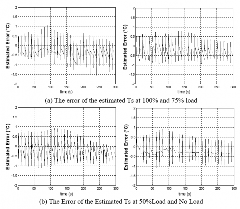
Figure 7. The ANFIS error of the estimated temperature at 50% and 75% Load
Figure 8. The estimated temperature by ANFIS at 25% load and no load
Figure 9. The ANFIS error of the estimated temperature at 50% and 75% load
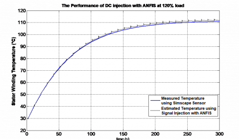
3.2.3.Testing the technique with abnormal conditions
A separate test covering a different operating condition for the motor operation was prepared. The asynchronous machine is loaded with120% of the rated load, to test the motor in overloading condition with 20%. Figure 10 displays the estimated Ts based on DC injection using ANFIS. It illustrates that, the temperature monitoring scheme using ANFIS provides a proactive manner to warn the user. The scheme alarms the user from stator winding overheating due to overload. As a result, the proposed scheme notifies the operator of the motor to de-load the motor or inspect it.
Figure 10. Stator winding temperature estimation under overload condition
The set of inputs of ANFIS should be selected carefully. The last case (first case), only the Irms and Tdc are the input data. This section illustrates which input and minimum sufficient number of inputs is better. The section checks which input set of the ANFIS scheme that gives the best output performance. Therefore additional two cases of input sets for ANFIS unite are presented beside the first case.
4.1. The second case of the input set to ANFIS scheme
The second case of the input data to the ANFIS unit is Irms, Rdc and Tdc. The output of the ANFIS unit is the stator winding temperature measured from the sensor. Hence the construction of the ANFIS architecture have three neurons in the input layer (for Irms, Rdc and Tdc) i.e. N=3. Then three gbell membership functions designed for each input i.e. M=3. The output is linear membership function. The training epochs equals to 300 epochs. A separate test set was prepared to this ANFIS scheme. It covers different loading conditions for motor operation. The induction motor is operated under 0%, 50%, 75% and 100% of the rated load. The estimated Ts using 2nd case ANFIS scheme is displayed in Figure 11. For validation purposes, it displays also the average temperature measured from the entrenched perfect temperature sensor. It displays the results of the different operating conditions in only one view. On the other hand, it is preferable to display the estimated error at each load separately. Therefore Figure 12 displays ANFIS error of the estimated temperature of the stator winding at 0%, 50%, 75% and 100% load. The composed errors are displayed to evaluating which set of inputs of ANFIS is better.
Figure 11. The stator winding temperature estimation results in second case at different operating conditions
Figure 12. The estimated temperature error of winding at no load, 25%, 50% and 100%Load for ANFIS second case
4.2. The third case of the input set to ANFIS scheme
The Irms, Vdc, Idcand Tdc are the input data to the ANFIS unit in the third case of the ANFIS inputs set. The stator winding temperature measured from the sensor is the output of ANFIS scheme. The construction of the ANFIS architecture has four neurons in the input layer (for Irms, Vdc, Idc and Tdc) i.e. N=4. Then three gbell membership functions designed for each input i.e. M=3 and the output is a linear membership function. The estimated error is preferable than displaying the estimated temperature in comparison phase. Ams mention later, for checking which set of inputs of ANFIS is better, displaying estimated temperature can be neglected. Consequently Figure 13 display ANFIS error of the estimated temperature of stator winding at 0%, 50%, 75% and 100% load.
To evaluate the performance of these ANFIS schemes, the following section compares among the estimated Ts considering different loading conditions.
4.3. Summarizing the ANFIS results for good comparison
The previous results are summarized in Table 2 to evaluate the performance of each ANFIS inputs set. Output error for each case is presented for different operating conditions. In addition, the minimum negative, maximum positive errors and the maximum Root Mean Square (RMS) error are shown in table 2. Moreover, the steady state temperatures are displayed for each loading case. As observed, the temperature scheme has better tracking of the winding temperature and minimum error in 1st case. The proposed scheme improves the accuracy of stator temperature estimation without affecting motor torque.
Figure 13. The estimated temperature error of winding at no load, 25%, 50% and 100% Load for ANFIS third case
Table 2. Comparison between presented ANFIS schemes
|
ANFIS Inputs Schemes Temperature Error |
1st case |
2nd case |
3th case |
S.S Temp. (◦c) |
|
|
Full load |
Min. –Ve Error (◦c) |
-1.077 |
-1.1792 |
-1.5762 |
83.2 |
|
Max. +Ve Error (◦c) |
1.003 |
0.981 |
1.249 |
||
|
Max. RMS Error(◦c) |
2.335 |
6.344 |
2.765 |
||
|
75% Load |
Min. –Ve Error (◦c) |
-1.173 |
-1.791 |
-0.949 |
60 |
|
Max. +Ve Error (◦c) |
0,892 |
0.936 |
0.807 |
||
|
Max. RMS Error(◦c) |
3.577 |
10.363 |
4.242 |
||
|
50% Load |
Min. –Ve Error (◦c) |
-0.995 |
-0.977 |
-1.100 |
45.9 |
|
Max. +Ve Error (◦c) |
0.948 |
1.196 |
0.905 |
||
|
Max. RMS Error(◦c) |
4.784 |
9.771 |
5.152 |
||
|
No Load |
Min. –Ve Error (◦c) |
-0.907 |
-0.739 |
-1.091 |
38.4 |
|
Max. +Ve Error (◦c) |
1.024 |
1.262 |
1.060 |
||
|
Max. RMS Error(◦c) |
3.231 |
10.111 |
4.0029 |
||
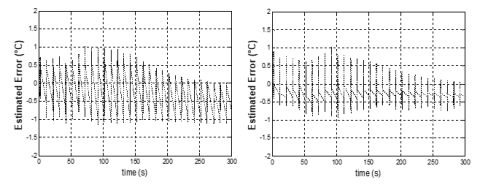
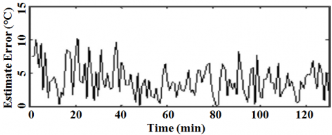
This part displays three results of the output error that used signal injection technique, to check the practicality of performance of the proposed technique. The three results are obtained from three different articles. Article (1) is published by Zhang et al. (2008). Article (2) is issued by Zhang et al. (2009). Article (3) is published by Enany et al., 2014. The previous three research works utilize the DC injection method with the same motor rating and same delay angle.
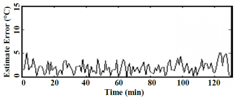
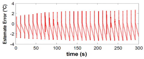
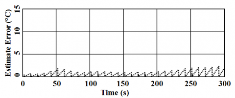
Figure 14(a) presents the estimated error of stator winding temperature in Article (1). The next Figure 14(b) displays the estimated error after filtered by the adaptive Kalman filter as displayed in Article (2). Alternatively, Figure 14(c) demonstrates the estimated error in Article (3). Figure 14(d) shows the estimated error of this research work that uses ANFIS. It can be seen in Figure 14 that maximum RMS error of the estimated temperature obtained by ANFIS is the minimum of them. It is around 2.3 (◦c).
Finally, Table 3 summarizes these results as follow. It displays the maximum RMS error for each presented articles results. In addition Table 3 shows the steady state temperature for the motor loaded condition. The percentage of error with respect to its steady state temperature case is illustrated also. Therefore the accuracy of the temperature estimation of stator winding using ANFIS is improved. Consequently the temperature of stator winding can be truthfully displayed.
(a) The estimated error of Ts estimation from [20]
(b) The estimated error of Ts estimation from [21]
(c) The estimated error of Ts estimation from [24]
(d) The Estimated error of Ts estimation using ANFIS
Figure 14. A comparison of the Ts estimation with other techniques
Table 3. Comparison between presented techniques
|
Results Obtained by Stator Temp. Case |
Article (1) |
Article (2) |
Article (3) |
This Article |
|
Max. RMS Error(◦c) |
10 |
5.2 |
4 |
2.3 |
|
S.S Temp. (◦c) |
60 |
60 |
83.2 |
83.2 |
|
Error Percentage (%) |
16.6 |
8.6 |
4.8 |
2.7 |
This research work presents a sensor-less and remote technique for temperature monitoring of the asynchronous motor. The DC signal injection technique is explained, to compute stator winding resistance/temperature using soft starter coupled to the asynchronous motor. The torque pulsation produced in asynchronous machine at TMM interval is evaluated with various magnitude of the delay angle. The maximal delay angle in the research work is considered that δ=15° to limit the torque pulsation under an acceptable level. ANFIS processes the value of the stator temperature that obtained from the DC injection, with other parameter such stator current to get an accurate stator winding temperature. Three cases of the input data to the ANFIS unit are simulated, in order to know which input and the least suitable number of inputs to ANFIS scheme that gives the best performance. From the simulation results, the error of the stator winding temperature estimation is 1°C at a 15° delay angle when the winding temperature varies from 25°C to 85°C. The result of temperature monitoring using ANFIS is compared with other techniques. Therefore a remote temperature monitoring and protection becomes practicable for winding of asynchronous motor. Respectable results are obtained.
Baneira F., Yepes A. G., López Ó., Doval-Gandoy J. (2016). Estimation method of stator winding temperature for dual three-phase machines based on dc-signal injection. IEEE Transactions on Power Electronics, Vol. 31, No. 7, pp. 5141-5148. https://doi.org/10.1109/TPEL.2015.2479410
Boglietti A., Carpaneto E., Cossale M., Borlera A. L., Staton D., Popescu M. (2014). Electrical machine first order short-time thermal transients model: Measurements and parameters evaluation. In Industrial Electronics Society, IECON 2014-40th Annual Conference of the IEEE, pp. 555-561. https://doi.org/10.1109/IECON.2014.7048555
Enany T. A., Wahba W. I., Hassan M. M. (2013). Thermal behavior for induction motor using DC signal injection method by Matlab® Simulation. In Modelling, Identification & Control (ICMIC), 2013 Proceedings of International Conference on, pp. 129-134.
Enany T. A., Wahba W. I., Hassan M. M. (2014). A remote and sensorless stator winding temperature estimation method for thermal protection for induction motor. International Journal of System Dynamics Applications (IJSDA), Vol. 3, No. 3, pp. 53-72. https://doi.org/10.4018/ijsda.2014070103
Fitzgerald A. E., Kingsley C., Umans S. D., James B. (2003). Electric machinery. New York: McGraw-Hill.
Gao Y., Muzzio F., Ierapetritou M. (2011). Characterization of feeder effects on continuous solid mixing using fourier series analysis. AIChE Journal, Vol. 57, No. 5, pp. 1144-1153. https://doi.org/10.1002/aic.12348
Hubert R., Aïcha A., Abderrezak R. (2003). Un modèle du moteur asynchrone à cage dédié à la simulation et au diagnostic. European Journal of Electrical Engineering, Vol. 6, No. 3-4, pp. 325-350.
Hurst K. D., Habetler T. G. (1997). A thermal monitoring and parameter tuning scheme for induction machines. In Industry Applications Conference, 1997. Thirty-Second IAS Annual Meeting, IAS'97., Conference Record of the 1997 IEEE, Vol. 1, pp. 136-142. https://doi.org/10.1109/IAS.1997.643019
Hussein H. T., Ammar M., Hassan M. M. (2016). induction motors stator fault analysis based on artificial intelligence. Indonesian Journal of Electrical Engineering and Computer Science, Vol. 2, No. 1, pp. 69-78.
Kamel T. S., Moustafa Hassan M. A., El-Morshedy A. (2012). Advanced distance protection technique based on multiple classified ANFIS considering different loading conditions for long transmission lines in EPS. International Journal of Modelling, Identification and Control, Vol. 16, No. 2, pp. 108-121. https://doi.org/10.1504/IJMIC.2012.047119
Karanayil B., Rahman M. F., Grantham C. (2003). Investigation of an on-line rotor resistance identification with a new stator resistance observer for induction motor drive using artificial neural networks. In Power Electronics Specialist Conference, 2003. PESC'03. 2003 IEEE 34th Annual, Vol. 4, pp. 1883-1888. https://doi.org/10.1109/PESC.2003.1217740
Kouroussis D., Kulali E. (2014). Smart-grid adaptive power management method and system with power factor optimization and total harmonic distortion reduction. U.S. Patent No. 8,874,277.
Lee S. B., Habetler T. G. (2001). An on-line stator winding resistance estimation technique for temperature monitoring of line-connected induction machines. In Industry Applications Conference, 2001. Thirty-Sixth IAS Annual Meeting. Conference Record of the 2001 IEEE, Vol. 3, pp. 1564-1571. https://doi.org/10.1109/TIA.2003.811789
Lu B., Habetler T. G., Harley R. G. (2008). A nonintrusive and in-service motor-efficiency estimation method using air-gap torque with considerations of condition monitoring. IEEE transactions on Industry Applications, Vol. 44, No. 6, pp. 1666-1674. https://doi.org/10.1109/TIA.2008.2006297
Matić P. R., Gecić M. A., Lekić, D. M., Marčetić D. P. (2015). Thermal protection of vector-controlled IM drive based on DC current injection. IEEE Transactions on Industrial Electronics, Vol. 62, No. 4, pp. 2082-2089. https://doi.org/10.1109/TIE.2014.2354015
Mellor P. H., Roberts D., Turner D. R. (1991). Lumped parameter thermal model for electrical machines of TEFC design. In IEE Proceedings B-Electric Power Applications, Vol. 138, No. 5, pp. 205-218. https://doi.org/10.1049/ip-b.1991.0025
Pugachev A. (2016). Simulation of induction motor temperature determination by additional voltage injections. In Industrial Engineering, Applications and Manufacturing (ICIEAM), International Conference on, pp. 1-5. https://doi.org/10.1109/ICIEAM.2016.7911506
Pugachev A., Fedyaeva G. (2015). Definition of the transfer function parameters of asynchronous motor as an object of temperature control. In Applied Mechanics and Materials, Vol. 698, pp. 124-130. https://doi.org/10.4028/www.scientific.net/AMM.698.124
Venkataraman B., Godsey B., Premerlani W., Shulman E., Thaku M., Midence R. (2005). Fundamentals of a motor thermal model and its applications in motor protection. In Protective Relay Engineers, 2005 58th Annual Conference for, pp. 127-144. https://doi.org/10.1109/CPRE.2005.1430428
Wahsh S., Shazly J., Yassin A. (2016). Steady state heat conduction problems of AFPMSM using 3D finite element. In Power Systems Conference (MEPCON), 2016 Eighteenth International Middle East, pp. 949-953. https://doi.org/10.1109/MEPCON.2016.7837011
Wu Y., Gao H. (2006). Induction-motor stator and rotor winding temperature estimation using signal injection method. IEEE Transactions on Industry Applications, Vol. 42, No. 4, pp. 1038-1044. https://doi.org/10.1109/IEMDC.2005.195787
Zhang H. (2015). Online thermal monitoring models for induction machines. IEEE Transactions on Energy Conversion, Vol. 30, No. 4, pp. 1279-1287. https://doi.org/10.1109/TEC.2015.2431444
Zhang P., Du Y., Lu B., Habetler T. G. (2009). A DC signal injection-based thermal protection scheme for soft-starter-connected induction motors. IEEE Transactions on Industry Applications, Vol. 45, No. 4, pp. 1351-1358. https://doi.org/10.1109/TIA.2009.2023410