Ala Houam* | Fares Zaamouche | Rabah Daouadi | Moussa Attia
© 2022 IIETA. This article is published by IIETA and is licensed under the CC BY 4.0 license (http://creativecommons.org/licenses/by/4.0/).
OPEN ACCESS
Due to the high efficiency, high power density and low EMI provided by the LLc resonant converter, it has been widely used by researchers in many fields such as induction heating (IH). This converter is based on a resonant circuit consisting of a capacitor (Cr) and two inductors Lr, Lm operating in wide output load regulating ranges for the purpose of achieving good efficiency for very high power systems using a high operating frequency. This paper aims to present a half-bridge LLC resonant converter based on power supplies for IH applications. The analysis contains five components: half bridge inverter, resonant tank, high frequency transformer, rectifier and coil. The switching bridge generates a square waveform to excite the LLC resonant tank, which will produce a resonant sinusoidal current which is transferred to the secondary of the converter through a high-frequency transformer. as it scales the voltage up or down according to the output requirements. The load represented by the equivalent circuit of the coil and work-piece is fed by the current transformed by the rectifiers. This paper provides an improved knowledge of the control of the output power for high-temperature applications through numerical simulation Considering that the load parameters and resonant frequency vary substantially throughout the system operation. The results of testing demonstrated that the proposed scheme and assembly has good efficiency, and it is well suited for magnetic induction heating systems.
half-bridge inverter, LLC circuit, resonant tank, induction heating, rectifier
Induction heating is an electro thermal method which involves the fields of electromagnetism and heat transfer. It is one of the most important heating methods of an electrically conductive material which can be a ferrous or non-ferrous metal without direct contact with it [1, 2].
Compared to the other heating techniques such as resistance heating; Induction heating is considered as the more efficient heating technique; Because the case of induction heating process heat is directly generated within the workpiece itself, unlike the resistance heating, the heating element will heat up first and then through the process of conduction, the heat energy will be transferred to the workpiece, which will take longer and eventually lead to more heat loss.
Induction heating process is widely used in industrial applications such as preheating furnaces, heat treatments, welding, brazing, melting, etc [3].
One of the most important reasons that contributed to the development of this complex multiphysical phenomenon is the progress of power semiconductor devices (MOSFETs and IGBTs), and control schemes in high-frequency circuits using advanced switching techniques [4, 5].
Different power switching schemes and control methods such as phase shift control (PSC) [6, 7] which is based on variation of output power by shifting the phase of the switch conduction sequences, Single-ended voltage cancellation (AVC) [8] where the control is based on voltage-cancellation for conventional fixed-frequency, The asymmetrical duty-cycle (ADC) control technique [9] which employs an unequal duty-cycle operation of the switches in the converter and DC-density modulation control Pulses (PDM) [10]; have made voltage source resonant inverters widely used in applications requiring output power control capability.
In high temperature applications, a high current must flow across the surface of the metal for a heating effect. Otherwise the main drawbacks of the series resonant inverter (SRI) that it may require a transformer to match the output power and the high current in the induction coil.
In an industrial environment, apart from the converter and the matching transformer, the design of the induction coil and its profile itself is critical to obtain the best performance. Induction coil design using ELTA that it is a systematic design procedure for the coil for proper matching of the converter with the coil [11].
Previous work has shown that an LLC configuration can provide better performance; in the study [12] the authors proposed a novel topology based on LLC and LCL-T resonant tanks to reduce the range of operating switching frequency. while [13] the proposed converter will have the ability to respond to the load changes by varying the switching frequency to the value that fulfils the requirement. In the study [14] they have found that LLC resonant structure [15] is suitable for working in low-voltage and high-current pattern whereas LCC is suitable for high voltage and low-current pattern.
This paper describes a half-bridge LLC resonant converter based on power supplies for induction heating in high temperature application. The validity and results are verified by MATLAB simulation.
The induction heating concerns the electromagnetic theory; Michael Faraday discovered that the alternating current flowing through the coil makes the magnetic field around the coil, the induced electromotive force in a closed loop equals the negative of the time rate of change of the magnetic flux through the loop.
$E=-N \frac{d \Phi_B}{d t}$ (1)
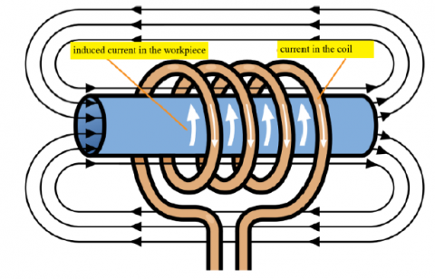
This EMF generates an alternating current (eddy current). Then, the basic principle of IH system is based on the creation of an eddy current within the workpiece when a conductive element is immersed in a variable magnetic field [16], the restriction of these currents due to the resistance of the material dissipates the energy and generates heat in the workpiece as shown in Figure 1.
Figure 1. Basic principle of IH
This process follows several stages: electromagnetic induction, skin effect and heat transfer. Furthermore, the heat depends on the amount of induced current. The equivalent resistance is transferred to other areas by convection, conduction and radiation on the surface. The basic principle of the induction heat is similar to that of the transformer operation [17].
3.1 Circuit description
The circuit consist five parts; the switching bridge (inverter) [18, 19], the resonant tank, a high frequency transformer, a rectifier and a load (coil+workpiece).
The half bridge LLC tank consists of two resonant inductors, a series inductor (Lr) and a magnetizing inductor (Lm), a resonant capacitor (Cr) and an induction coil that comprises a series combination of a resistor (Req) and an induction coil inductor (Lcoil).
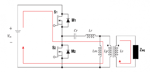
The main power circuit features of a half bridge LLC resonant converter are illustrated in Figure 2.
Figure 2. half bridge LLC resonant converter
The switching bridge generates a high-frequency square wave by switching and converting the DC voltage to excite the LLC resonant tank, this last then enters the resonant tank, which eliminates the square wave harmonics and gives the output as a sine wave of the fundamental frequency [20].
The sine-wave rectifier and the filter capacitor provide the DC output voltage Vo for the load ZLoad. The nonlinear model of the converter can be obtained by the following equations.
$\frac{d i_{L r}}{d t}=\frac{1}{L_r}\left(V_{i n}-V_{c r}-V_{L m}\right)$ (2)
$\frac{d V_{c r}}{d t}=\frac{i_{L r}}{C_r}$ (3)
$\frac{d V_0}{d t}=N\left(i_{L r}-i_{L m}\right)-\frac{V_0}{R_{e q}}$ (4)
$\frac{d i_{L m}}{d t}=\frac{V_{L m}}{L_m}$ (5)
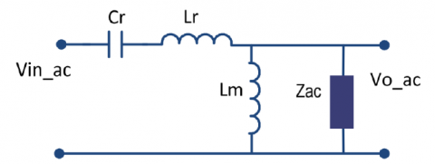
The resonant tank gain can be derived by analyzing the equivalent resonant circuit shown in Figure 3.
Figure 3. Equivalent LLC resonant tank circuit
The resonant tank gain is the magnitude of its transfer function as in Eq. (6) [21].
$k=\frac{F_x^2(m-1)}{\sqrt{\left(m \cdot F_x^2-1\right)^2+F_x^2 \cdot\left(F_x^2-1\right)^2 \cdot(m-1)^2 \cdot Q^2}}$ (6)
$Q=\frac{\sqrt{L_r / C_r}}{Z_{a c}}$ (7)
The sine wave is transferred to the secondary of the converter through a high-frequency transformer which scales the voltage up or down according to the output requirement, lastely the diode rectifier convert the sine wave into a stable DC output.
$Z_{a c}=\frac{8}{\pi^2} \cdot \frac{N_P^2}{N_S^2} \cdot Z_{a c}$ (8)
$m=\frac{L_r+L_m}{L_r}$ (9)
According to another way of designating resonant converters, the LLC resonant half-bridge belongs to the family of multi-resonant converters. Actually, there are two resonant frequencies associated to this circuit fr and fm. the first is related to the series resonant elements Lr and Cr as in Eq. (10) [22, 23].
$f_r=\frac{1}{2 \pi \sqrt{L_r \times C_r}}$ (10)
And when the resonant elements Lr and Cr resonate with the parallel resonance element Lm. here, new frequency fs is provided as in Eq. (11).
$f_s=\frac{1}{2 \pi \sqrt{\left(L_r+L_m\right) \times C_r}}$ (11)
3.2 Modes of operation
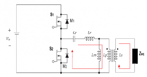
As shown in next figures, four modes of operation exist within one switching cycle. The corresponding circuit topology for each mode of operation is shown in Figures 4(a), (b), (c), (d) respectively. The analysis is as follows.
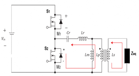
Stage 1: MOSFET M1 is turned on and M2 is turned off the current flows from Vin to the switching bridge source of MOSFET (M1) to capacitor (Cr), resonant inductor (Lr), and primary coil of Lp. Then energy will be transferred to secondary coil of Ls, Figure 4(a).
-Figure 4(a)-
Stage 2: MOSFET M1 and M2 are turned off; resonant inductor (Lr) will release an energy to primary coil of Lp, diode of (M2), and capacitor (Cr). Then primary side of Lp coil will transfer the energy to secondary coil of Ls. The mode 2 is shown in Figure 4 (b).
-Figure 4(b)-
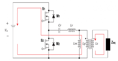
Stage 3: MOSFET M1 is turned off and M2 is turned on. The current flows from capacitor (Cr), MOSFETs (M2) and primary coil of Lp. Then the Lp will transfer the energy to secondary coil of Ls. The mode 3 is shown in Figure 4 (c).
-Figure 4(c)-
Stage 4: MOSFETs M1 and M2 are turned off. The energy in resonant inductor (Lr) is released to capacitor (Cr), diode of (M1), Vin, and primary coil of Lp. The mode 4 is shown in Figure 4 (d).
-Figure 4(d)-
Figure 4. Operation mode of half bridge resonant inverter
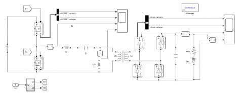
Using Simulink /MATLAB software, we have created the assembly of Figure 5 which represents the block diagram of half bridge LLC resonant converter, and then created a control circuit to obtain the command signal (S1 and S2) to control the MOSFETs (M1 and M2) as shown in Figure 6. In order to validate and test our assembly, we used the different parameters which are shown in the Table 1.
Table 1. The parameters of the LLC resonant converter
|
Item |
Symbol |
Value |
|
Input Voltage |
Vin |
220V |
|
Switching Frequency |
fs |
100 kHz |
|
Parallel resonant capacitor |
Cr |
0.1 µF |
|
resonant inductor |
Lr |
22.6 µH |
|
magnetizing inductor |
Lm |
80 µH |
|
Equivalent resistor (with workpiece) |
Req |
5Ω |
|
Equivalent inductor |
Leq |
1.2 µH |
Figure 5. Simulation model of half bridge LLC resonant converter
Figure 6. Pulse generator (variable switching frequency)
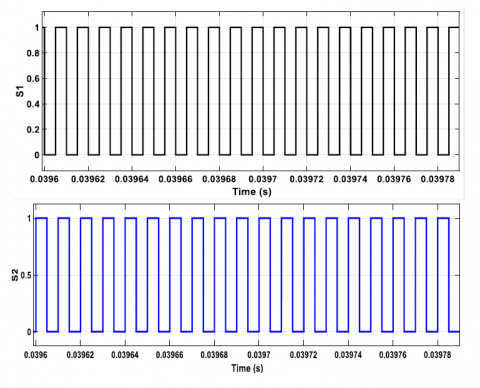
The Figure 7 shows the command signal (S1 and S2) to control the MOSFETs (M1 and M2) at the top and bottom of the half-bridge converter respectively. While applying the gating pulse to the MOSFET it is necessary to take care of the overlapping of ON time and OFF time of two semiconductor switches. If 2nd MOSFET is given the pulse before the prior one is not completely OFF, it may cause short circuit and thus failure of the semiconductor device. Therefore the control of this switches must be complementary.
Figure 7. Signals generated for the control of a half-bridge inverter
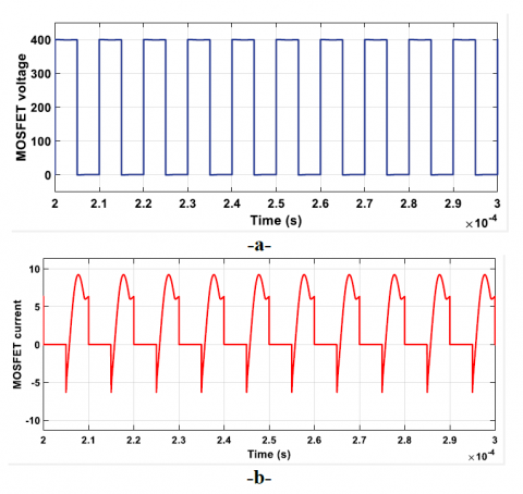
The Figure 8 show the voltage and current waveforms at the M1 switch on the top of the converter. When the switch is in the blocked state, the voltage takes the value of the source DC at 400 volts; otherwise it takes the value of zero volts, and the current reaches about 9 amps. The appearance of the negative part of the current resulting from the change of the states of the switch.
Figure 8. MOSFET voltage and current on the top a half-bridge converter
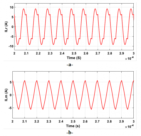
Figure 9 demonstrates the envelope of the current in the resonant circuit. Figure 9(a) shows the current at the output of the half-bridge inverter and flowing through the series inductance Lr. We see that it is an alternating current and not sinusoidal, because of the existence of harmonics. It is corrugated between [-9, +9] amperes around. The current through the magnetizing inductance Lm is presented by Figure 9(b). We observe that, it is also an alternating current with less harmonics and filtered by the value of 80 µH, it is now rippled between [-6, +6] amperes around.
Moreover, the resonance frequency value is calculated as 50 kHz from the period value of the curve by Eq. (11). In this case, the switching frequency of the MOSFETs is double to the resonant frequency.
Figure 9. Output currents across the resonant tank
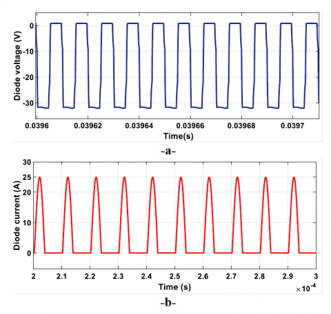
The Figure 10 presents the voltage and current waveforms at the diode D1 on the top corner left at the rectifier converter. When the diode is in the blocked state, the voltage is measured at the value of -60 volts; otherwise it takes the value of zero volts, and the current reaches about 23 amps.
Figure 10. Diode voltage and current on the top corner left at the rectifier converter
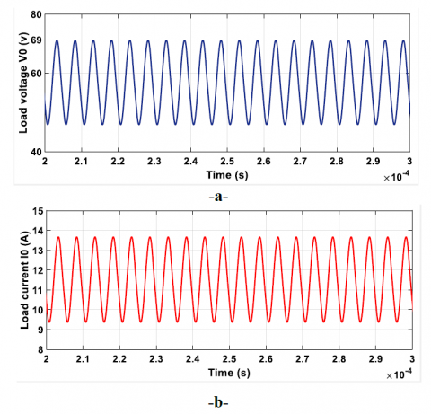
Figure 11 shows the voltage and current waveforms at the load terminal (Req and Leq). The rectified voltage is measured at the value of 60 volts around, and the current reaches about 11.5 amps.
Figure 11. Output voltage and current Waveforms
From the results mentioned above, it was confirmed that the proposed scheme and assembly have good efficiency, especially that the system showed great response by controlling the first transformer by using a mathematical model that allowed to give the command signal (S1 and S2) to control the MOSFETs, the use of MOSFETs allowed us to operate at high frequencies and it is well suited for magnetic induction heating systems.
In this paper, an improved half-bridge LLC resonant inverter topology for an induction heating application has been proposed. The validity of the proposed scheme is verified by the simulation results. The half-bridge resonant inverter with the parameters of the resonant tank and with the combination of the two static converters provides an excellent power supply for the induction heating.
the half bridge inverter can get more steady output current waveform with minimal fluctuation. half-bridge requires half the primary number of turns for the same voltage gain and magnetic flux swing. The analysis of LLC topology proved that this model is capable of giving better results than CLC and SLR. The simulation results illustrate its promising for high-frequency induction heating applications.
This work paves way for more investigations on the application of thermal shear, wireless charging applications.
In perspective, we intend to carry out the experimental part of this study and to compare it with the simulation results.
The authors gratefully acknowledge Mining Institute, Echahid Cheikh Larbi Tebessi University, Algeria for supporting this work.
|
Cr |
the resonant capacitor, (µF) |
|
E |
electromotive force, (V) |
|
Fx |
Normalized switching frequency |
|
iLr |
the resonant current, (A) |
|
iLm |
the magnetizing current, (A) |
|
m |
Ratio of total primary inductance to resonant inductance |
|
N |
number of turns of magnetic field |
|
Q |
the quality factor |
|
Req |
load resistor, (Ω) |
|
vcr |
the resonant capacitor voltage, (V) |
|
vLm |
the magnetizing voltage of Lm, (V) |
|
Vo |
the DC output voltage, (V) |
|
Zac |
the Reflected load resistance, (Ω) |
|
ФB |
the magnetic flux, (Wb/m2) |
|
Lr |
the series inductor, (mH) |
|
Lm |
the magnetizing inductor, (mH) |
|
Lcoil |
induction coil inductor, (mH) |
[1] Kim, D.S., So, J.Y., Kim, D.K. (2016). Study on heating performance improvement of practical induction heating rice cooker with magnetic flux concentrator. IEEE Transactions on Applied Superconductivity,26(4):1-4. https://doi.org/10.1109/TASC.2016.2540650
[2] Sarnago, H., Lucía, O., Burdio, J.M. (2018). A versatile resonant tank identification methodology for induction heating systems. IEEE Transactions on Power Electronics, 33(3):1897-1901, https://doi.org/: 10.1109/TPEL.2017.2740998
[3] Hameed, M., Abdulbaqi, I., R. H. (2016). Modeling, design and analysis of an induction heating coil for brazing process using FEM. Al-Sadeq International Conference on Multidisciplinary in IT and Communication Science and Application, IRAQ. https://doi.org/10.1109/AIC-MITCSA.2016.7759918
[4] Wang, C, M., Chen, G.Y. (2017). A ZVS-PWM Single-phase inverter using a ZVS transformer-isolated step-up/down dc link. 2017 IEEE 3rd International Future Energy Electronics Conference and ECCE Asia (IFEEC 2017 - ECCE Asia). https://doi.org/10.1109/IFEEC.2017.7992122
[5] Arun. K.P. (2020). ZVZCS SRI guides optimal use of copper and core for air-cooled nanocrystalline transformer for induction heating. IEEE Transactions on Industry Applications, 56(2): 970-978. https://doi.org/10.1109/TIA.2020.2967329
[6] Vishnuram, P., Kumar, S., Singh, V.K., Babu, T.S., Kannan, R., Hasan, K.N.B.M. (2022). Phase shift-controlled dual-frequency multi-load converter with independent power control for induction cooking applications. Sustainability, 14(16): 10278. https://doi.org/10.3390/su141610278
[7] Sreejyothi, K.R., Kumar, V., Chenchireddy, K., Tejaswi, P. (2022). Zero Voltage Switching (ZVS)-based DC–DC converter for battery input application. AI Enabled IoT for Electrification and Connected Transportation. https://doi.org/10.1007/978-981-19-2184-1_11
[8] Ngamrungsiri, H., Naetiladdanon, S., Sangswang, A. (2016). A variable-frequency asymmetrical voltage-cancellation control for inductive power transfer with series-series compensation. 13th International Conference on Electrical Engineering/Electronics, Computer, Telecommunications and Information Technology (ECTI-CON), pp. 1-6. https://doi.org/10.1109/ECTICon.2016.7561311
[9] Balbi, H.D., Carrano, R.C., Passos, D. (2019). Revisiting probabilistic schedule-based asynchronous duty cycling. Int J Wireless Inf Networks 26, 24-38. https://doi.org/10.1007/s10776-018-0420-5)
[10] Lee, J. H., Son, W. J., Ann, S., Byun, J., Lee, B. K. (2019). Improved pulse density modulation with a distribution algorithm for semi-bridgeless rectifier of inductive power transfer system in electric vehicles. 10th International Conference on Power Electronics and ECCE (ICPE 2019 - ECCE Asia), Busan, Korea (South), pp. 1-6. https://doi.org/10.23919/ICPE2019-ECCEAsia42246.2019.8797336
[11] Bukanin, V., Ivanov, A., Zenkov, A. (2020). Investigation of heating and melting in ELTA programs. COMPEL - The International Journal for Computation and Mathematics in Electrical and Electronic Engineering, 39(1): 117-124. https://doi.org/10.1108/COMPEL-05-2019-0219
[12] Wei, Y., Luo, Q., Mantooth, H.A. (2021). An LLC and LCL-T resonant tanks based topology for battery charger application. CPSS Transactions on Power Electronics and Applications, 6(4): 263-275. https://doi.org/10.24295/CPSSTPEA.2021.00025
[13] Salem, M., Ramachandaramurthy, V.K., Jusoh, A., Sanjeevikumar, P., Kamarol, M., Teh, J., Ishak, D. (2020). Three-phase series resonant DC-DC boost converter with double LLC resonant tanks and variable frequency control. IEEE Access, 8(1): 22386-22399. http://dx.doi.org/10.1109/ACCESS.2020.2969546
[14] Zheng, J., Lu, S., Li, J. (2020). LLC and LCC analysis and comparison of resonant converters. In 2020 35th Youth Academic Annual Conference of Chinese Association of Automation (YAC). http://dx.doi.org/10.1109/YAC51587.2020.9337641
[15] Esteve, V., Jordán, J., Dede, E.J., Sanchis-Kilders, E., Martinez, P. J., Maset, E., Gilabert, D. (2021). Optimal LLC inverter design with SiC MOSFETs and phase shift control for induction heating applications. IEEE Transactions on Industrial Electronics, 69(11): 11100-11111. https://doi.10.1109/TIE.2021.3121730
[16] Patil, M., Choubey, R.K., Jain, P.K. (2022). Influence of coil shapes on temperature distribution in induction heating process. Materials Today: Proceedings. https://doi.org/10.1016/j.matpr.2022.08.376
[17] Lucía, O., Maussion, P., Dede, E.J., Burdío, J.M. (2013). Induction heating technology and its applications: past developments, current technology, and future challenges. IEEE Transactions on industrial electronics, 61(5): 2509-2520. https://doi: 10.1109/TIE.2013.2281162
[18] Zaamouche, F., Saad, S., Hamiche L. (2020). Discontinuous PWM applied for a three-phase five-level CHB inverter fed by PV solar-boost converter. European Journal of Electrical Engineering, 22(2): 153-161. https://doi.org/10.18280/ejee.220209
[19] Houam, A., Zaamouche, F., Ounnas, D. (2022). DPWM applying for five-level NPC VSI powered by PV-boost converter based on Takagi Sugeno Fuzzy Model. European Journal of Electrical Engineering 24(2): 105-112. https://doi.org/10.18280/ejee.240205
[20] Li, H., Zou, Y., Jiang, X., Liu, C. (2020). A time-domain stability analysis method for LLC resonant converter based on Floquet theory. Microelectronics Reliability, 114, 113850. https://doi.org/10.1016/j.microrel.2020.113850
[21] Murali, D., Annapurani, S. (2021). Improvement of static voltage gain of a non-isolated positive output single-switch DC-DC converter structure using a diode-capacitor cell. Mathematical Modelling of Engineering Problems, 8(4): 583-590. https://doi.org/10.18280/mmep.080411
[22] Ma, W., Xie, X., Jiang, S. (2017). LLC resonant converter with variable resonant inductor for wide LED dimming range. IEEE Applied Power Electronics Conference and Exposition - APEC, USA, pp. 2950-2957. https://doi.org/10.1109/APEC.2017.7931116
[23] Haema, J., Phadungth, R. (2018). Development of LLC resonant inverter for saw blade induction eating applications. 5th International Conference on Electric Power and Energy Conversion Systems, EPECS. http://dx.doi.org/10.1109/EPECS.2018.8443350