Ala Houam* | Fares Zaamouche | Djamel Ounnas
© 2022 IIETA. This article is published by IIETA and is licensed under the CC BY 4.0 license (http://creativecommons.org/licenses/by/4.0/).
OPEN ACCESS
Power quality is interesting issue for power conversion PV system. Further there are challenges associated with extract of maximum power and minimize the part losses in commutation. In this paper, a three-phase five-level NPC voltage source inverter (VSI) using discontinuous pulse-width modulation (DPWM) and feeding by a PV/DC-DC boost converter based on a Takagi-Sugeno T-S fuzzy controller is presented. The photovoltaic energy system is described by nonlinear equations. A T-S fuzzy model is used to transform the nonlinear equations into a fuzzy model by modeling the irradiation, temperature and output voltage parameters. The control parameters have been computed based on Linear Matrix Inequalities tools (LMI) and the stability of the system is ensured by Lyapunov approach. In the second stage for power conversion (DC/AC), a discontinuous pulse-width modulation (DPWM) is used and approved; it offers the possibility of reducing switching losses and the THD harmonic rate. The simulation was performed in the MATLAB/Simulink software using an R-L load and the obtained results are confirmed the feasibility and reliability of the proposed method for the PV conversion system.
PV system, boost converter, T–S fuzzy model, LMIs, NPC inverter, DPWM
The global trend towards renewable energies has become an unavoidable urgency to find new energy alternatives to produce electricity, given the growing demand for it on the one hand, and the waste of fossil energy resources used by the traditional method on the other hand [1]. But the main reason for this trend remains global warming and environmental pollution.
Among renewable energy sources, solar energy allocates major part due to the advantage that it offers like sustainable, clean and minimal maintenance, the factors that characterize the energy produced by a PV system are the irradiation, the temperature and the output voltage of each PV module.
The functions of the power converter stage of a PV system include maximum power point tracking MPPT [2, 3] DC to DC, control of voltage source inverter (VSI), grid code compliance, active and reactive power control and anti-islanding detection.
Moreover, several studies have dealt with the efficiency of the PV system, focusing on the control of DC-DC boost converters by using linear controllers such as P, PI and PID [4] or nonlinear and advanced control techniques such as sliding mode [5], linearization control, and fuzzy logic controller (FLC) [6]; and neglecting the control of VSI [7, 8].
Among the best suitable power electronic device as switch-mode DC to AC is Multi-Level Inverters (MLIs) [9]. So many MLIs topologies have been proposed by researchers such as cascaded H-bridge (CHB) [10, 11], Flaying capacitors and the neutral point clamped NPC inverters [12-14]. The generation of the inverter control signals is based on the concept of pulse width modulation (PWM) which allows both to control the output voltage and to reduce the current harmonics in order to supply the AC load with consistent power quality [15].
In the last decades many researchers have developed several PWM techniques. This last can be divided into two families, the first includes all continuous PWM strategies such as (SPWM, SVPWM, THIPWM ...) [16, 17] which require a pulse timing diagram with continuous switching. While the second carries discontinuous strategies such as (DPWM_max, DPWM_min, DPWM_1 …) which require a timing diagram with discontinuous switching [18, 19].
In this paper and in its first part a new MPPT controller based on Takagi Sugeno fuzzy T-S [20] model is proposed to describe the nonlinear model of PV system. Next, an optimal PV voltage was generated using an ANFIS [21] algorithm using solar irradiation and cell temperature as inputs to design an optimal reference model ORM. The stability of the system is analyzed by Lyapunov’s method and described by LMI expressions [22].
While in the second part and to improve the power supply quality of the AC load, the neutral point clamped NPC type five-level voltage inverter topology was used. The control of the opening and closing of the transistors forming our inverter is carried out by the discontinuous pulse width modulation strategy DPWM, which is based on to inject the zero sequence component (ZSC) to the sinusoidal reference waves, and offers the possibility of reducing switching losses and the total harmonic distortion (THD) rate [23, 24].
This work has been divided into five parts as follows: After the introduction in the first part. The PV panel and boost converter based on T-S fuzzy controller are explained in the second part. The third part provides an overview of five-level NPC inverter topology and DPWM strategy. The simulation, discussion and interpretation results that validate the algorithms and the schemes used in this work are shown in the fourth part. Finally, a conclusion is made in the last part.
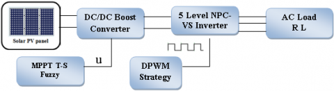
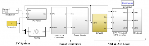
The configuration of the complete system is shown in Figure 1. A photovoltaic panel is connected to a Boost converter which is intended to increase the voltage up to the input of DC/AC level of the VSI. A T-S fuzzy based control has been developed to extract maximum power MPP. The control of the VSI unit is based on pulse width modulation technique (PWM). The output of the VSI is connected to a load R-L.
Figure 1. Complete system configuration developed
2.1 Photovoltaic array
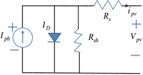
The most popular circuit equivalent to a solar cell/panel is shown in Figure 2. It includes a current source, one diode and two resistors: one in series Rs and one in parallel Rsh.
Figure 2. Electrical equivalent scheme of PV panel
The voltage/current characteristic equation of the PV array can be described by:
$I_{P V}=N_{P} I_{P h}-N_{P} I_{S}\left[\operatorname{Exp}\left(\frac{q\left(V_{P V} +R_{S} I_{P V}\right) V_{P V}}{K T A}\right)-1\right]-\frac{V_{P V} +R_{S} I_{P V}}{R_{S h}}$ (1)
where, Vpv and Ipv, denote the output voltage and current of the PV array, respectively. and:
$I_{P h}=G\left(I_{S C}+K_{I}\left(T-T_{r}\right)\right)$ (2)
$I_{S}=I_{r s}\left(\frac{T}{T_{r}}\right)^{3} \operatorname{Exp}\left[\frac{q E_{g}}{K A}\left(\frac{1}{T_{r}}-\frac{1}{T}\right)\right]$ (3)
$I_{r s}=\frac{I_{s c}}{\operatorname{Exp}\left[\frac{q V_{o c}}{N_{S} K A T}\right]}$ (4)
where, Iph, Irs and Is represent the light-generated current, short-circuit current (at 25◦Cand 1 kW/m2) and cell saturation of dark current, respectively. q, k, T, KIand A are the electron charge, Boltzmann constant, cell temperature, cell short-circuit current temperature coefficient and the ideal factor, respectively.
2.2 Boost converter model
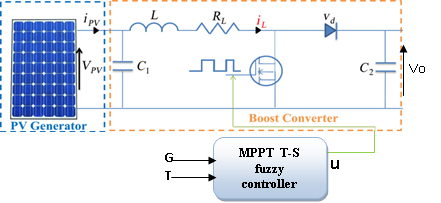
The main role of these electronic devices is to step up the voltage from their input to their load by a switching action (ON or OFF). Therefore, to adjust the PV array power, a DC/DC boost converter is connected to the PV array, as shown in Figure 3.
Figure 3. DC/DC boost converter based MPPT T-S fuzzy controller
According to Figure 3, the dynamic model of the DC/DC boost converter is described by the following equations:
$\left\{\begin{array}{l}i_{l}=-\frac{R_{L}}{L} i_{L}+\frac{1}{L} V_{P V}-\frac{1-u}{L}\left(V_{0}+v_{d}\right) \\ V_{P V}=-\frac{1}{C_{1}} i_{L}+\frac{1}{C_{1}}\end{array}\right.$ (5)
where, RL is the winding resistance of the inductor, VD is the threshold voltage of the diode, iL, Vo and u represent, respectively, the inductance current, the output voltage and the duty cycle of the boost converter.
Among the most widely used MPPT control techniques are the fuzzy logic controller, which in turn are models where the relationships between different variables are represented by fuzzy if-then rules with pre and post parts.
We distinguish two types of fuzzy models depending on the shape of the consequent part; the first is the linguistic model Mamdani where the two parts (the antecedent and the consequent) are fuzzy rules. The second is the Takagi-Sugeno (T-S) fuzzy model in which the input type (antecedent) is fuzzy and the output is a mathematical function.
2.2.1 T–S fuzzy control method
Several studies have been proving that the Takagi-Sugeno fuzzy system can describe the nonlinear energy conversion system, this technique represents a nonlinear system as a fuzzy average of the linear models Mi={Ai, Bi, Ci, Ei}.
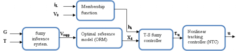
The first step is to develop a fuzzy controller (FC) based on T–S fuzzy model of the PV system. Next, a nonlinear tracking controller (NTC) and optimal reference model (ORM) are designed according to an optimal voltage calculated using a fuzzy inference system FIS as shown in the Figure 4, the control parameters have been computed based on Linear Matrix Inequalities (LMI). The Lyapunov approach has been used to prove the stability of the system [25, 26].
Figure 4. Diagram of the T-S fuzzy model
The transformation of the nonlinear model Eq. (5) into a fuzzy model requires the use of the output load voltage VOand the boost inductance current iLas decision variables, which gives the following non-linear state space form:
$\left\{\begin{array}{c}\dot{x}(t)=A x(t)+B u(t)+\eta(t) \\ y(t)=C_{x}(t)=V_{0}\end{array}\right.$ (6)
where, $A=\left[\begin{array}{ccc}-\frac{R}{L} & \frac{1}{L} & \frac{v_{0}+v_{d}}{L} \\ -\frac{1}{c_{1}} & 0 & 0 \\ 0 & 0 & 0\end{array}\right], B=\left[\begin{array}{l}0 \\ 0 \\ 1\end{array}\right] \eta=\left[\begin{array}{c}-\frac{v_{0}+v_{d}}{L} \\ \frac{1}{c_{1}} i_{p v} \\ 0\end{array}\right]$.
Assuming that premise variables are Z1=iL and Z2=Vo, the nonlinear system Eq. (6) can be described by a T–S model with r=22 fuzzy if–then rules as follows:
If z1(t) is Mi and z2(t) is Ni Then:
$\dot{x}(t)=A_{i} x(t)+B_{i} u(t)+\eta(t) ; i=1 . .4$ (7)
The membership functions M1, M2, N1 and N2 are given using the max (M) and min (M) values of the premise variables:
$\left\{\begin{array}{l}M_{1}=\frac{i_{l}(t)-i_{l m}}{i_{l M}-i_{l m}} \,\,\, ; M_{2}=1-M_{1} \\ N_{1}=\frac{V_{0}(t)-V_{0 m}}{V_{0 M}-V_{0 m}}\,\,\, ; N_{2}=1-N_{1}\end{array}\right.$ (8)
The T-S observer has the following form:
$\dot{x}=\sum_{i=1}^{r} h_{i}(z(t))\left(A_{i} x(t)+B_{i} u(t)\right)+\eta(\mathrm{t})$ (9)
where, $h_{i}(z)=\frac{\omega_{i}(z)}{\sum_{i=1}^{r} \omega_{i}(z)}$, and $\omega_{i}(z)=\prod_{j=1}^{r} M_{i j} N_{i j}\left(z_{i}\right)$.
In order to find a fuzzy controller capable of driving the state of the PV system x(t) to follow an optimal reference model xop(t). We introduce a new control variable τu(t) that satisfies the following relation:
$\sum_{i=1}^{r} h_{i} B_{i} \tau_{u}=\sum_{i=1}^{r} h_{i}(z)\left(A_{i} x_{o p}+B_{i} u\right)+\eta-\dot{x}_{o p}$ (10)
2.3 VSI topology and control method
As the VSI is the interface between the boost converter and the AC load, it is necessary to use a multilevel inverter topology (MLI). In accordance with the requirements and guarantees the capabilities of more output voltage levels, and larger power handling ability [27].
Moreover, Several MLIs and their modulation techniques have been established in the literature, such as cascaded H-bridge (CHB), flying capacitor (FC) and neutral point clamped (NPC) [28].
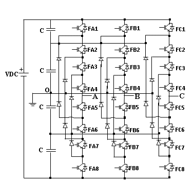
In this work, a three-phase five-level NPC inverter is used, which consists of three arms, each arm is built of eight transistors connected in series as shown in Figure 5, which can generate five different sinusoidal waveforms voltage outputs +2VDC, +VDC, 0, –2VDC and –VDC and offers the potential for AC system phase-balancing.
Figure 5. Three phase five level NPC VSI
2.3.1 Five level VSI NPC modeling
In this work, a 3-ph-five level NPC inverter is used, that consists of three single-phase arms, each arm has eight IGBTs/Diodes. Four switches which are mounted at the top and four at the bottom. The DC bus voltage is divided into four by the use of four capacitors of the same values as in Figure 5. Therefore, we must know the mathematical model of this DC/AC static converter.
Generally, the output voltages of three-phase inverters are modeled as follows:
$\left[\begin{array}{l}V_{A B} \\ V_{B C} \\ V_{C A}\end{array}\right]=\left[\begin{array}{ccc}1 & -1 & 0 \\ 0 & 1 & -1 \\ -1 & 0 & 1\end{array}\right]\left[\begin{array}{l}V_{A N} \\ V_{B N} \\ V_{C N}\end{array}\right]$ (11)
$\left[\begin{array}{l}V_{A N} \\ V_{B N} \\ V_{C N}\end{array}\right]=\frac{1}{3}\left[\begin{array}{ccc}2 & -1 & -1 \\ -1 & 2 & -1 \\ -1 & -1 & 2\end{array}\right]\left[\begin{array}{l}V_{A O} \\ V_{B O} \\ V_{C O}\end{array}\right]$ (12)
where, VAB, VBC, VCA is the vector of line-to-line voltages at the output of the inverter, VAN, VBN, VCN is the vector of line-to-neutral voltages at the output of the inverter, VAO, VBO, VCO is the vector of the intermediate voltages between the line and the neutral point O of the inverter.
The following equation shows the vector of the intermediate voltages:
$\left[\begin{array}{l}V_{A O} \\ V_{B O} \\ V_{C O}\end{array}\right]=\frac{V_{D C}}{4}\left\{\left[\begin{array}{l}F_{A}^{T} \\ F_{B}^{T} \\ F_{C}^{T}\end{array}\right]-\left[\begin{array}{c}F_{A}^{B} \\ F_{B}^{B} \\ F_{C}^{B}\end{array}\right]\right\}$ (13)
where, $\left[\begin{array}{lll}F_{A}^{T} & F_{B}^{T} & F_{C}^{T}\end{array}\right]$ is a vector which represents a control function for the transistors which are mounted at the top of the same arm, $\left[\begin{array}{lll}F_{A}^{B} & F_{B}^{B} & F_{C}^{B}\end{array}\right]$ is a vector which represents a control function for the transistors which are mounted at the bottom of the same arm.
$\left[\begin{array}{l}F_{A}^{T} \\ F_{A}^{B}\end{array}\right]=\left[\begin{array}{l}F_{A 1} \\ F_{A 5}\end{array}\right]\left[\begin{array}{l}F_{A 2} \\ F_{A 6}\end{array}\right]+\left[\begin{array}{l}F_{A 3} \\ F_{A 7}\end{array}\right]\left[\begin{array}{l}F_{A 4} \\ F_{A 8}\end{array}\right]$ (14)
$\left[\begin{array}{l}F_{B}^{T} \\ F_{B}^{B}\end{array}\right]=\left[\begin{array}{l}F_{B 1} \\ F_{B 5}\end{array}\right]\left[\begin{array}{l}F_{B 2} \\ F_{B 6}\end{array}\right]+\left[\begin{array}{l}F_{B 3} \\ F_{B 7}\end{array}\right]\left[\begin{array}{l}F_{B 4} \\ F_{B 8}\end{array}\right]$ (15)
$\left[\begin{array}{c}F_{C}^{T} \\ F_{C}^{B}\end{array}\right]=\left[\begin{array}{l}F_{C 1} \\ F_{C 5}\end{array}\right]\left[\begin{array}{l}F_{C 2} \\ F_{C 6}\end{array}\right]+\left[\begin{array}{l}F_{C 3} \\ F_{C 7}\end{array}\right]\left[\begin{array}{l}F_{C 4} \\ F_{C 8}\end{array}\right]$ (16)
Knowing that: $F_{i j}:\left\{\begin{array}{c}i=A, B \text { and } C \\ j=1,2,3, \ldots .8\end{array}\right.$.
2.3.2 Discontinuous PWM applied for five level NPC-VSI
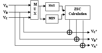
The tree-phase five levels NPC VSI is a converter with twenty four switches which requires a good PWM control strategy. In this work, we have chosen the DPWM strategy which offers the possibility of reducing the number of switching in the inverter. The basic principle of this technique is to inject the zero sequence component (ZSC) to the sinusoidal reference waves, with the aim of blocking each phase for 30 degrees in four times compared to the modulation period which is 360 degrees, to generate a balanced three-phase system. The following Figure 6 shows the block diagram of this strategy.
(a) Reference signals (VA*, VB* and VC*)
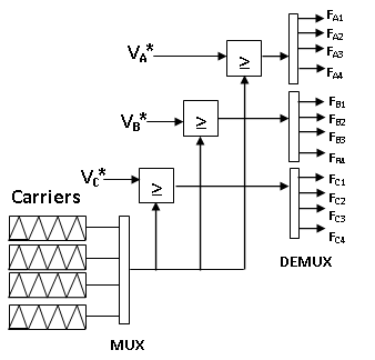
(b) Generation of the pulses to the switches.
Figure 6. Block diagram of the DPWM
$\left[\begin{array}{l}V_{A R} \\ V_{B R} \\ V_{C R}\end{array}\right]=\frac{M \cdot V_{D C}}{2}\left[\begin{array}{c}\sin (2 \pi f t) \\ \sin \left(2 \pi f t-\frac{2 \pi}{3}\right) \\ \sin \left(2 \pi f t-\frac{4 \pi}{3}\right)\end{array}\right]$ (17)
$\left[\begin{array}{l}V_{M A X} \\ V_{M I N}\end{array}\right]=\left[\begin{array}{c}M A X\left(V_{A R}, V_{B R}, V_{C R}\right) \\ M I N\left(V_{A R}, V_{B R}, V_{C R}\right)\end{array}\right]$ (18)
where, M: The modulation index; VDC: The output voltage of the boost converter; f: The output frequency to generate an AC system with 50 Hz; VMAX and VMIN: The maximum and the minimum components between the reference waves (VAR, VBR and VCR) respectively.
The following equation shows the ZCS component:
$Z C S=-\left[\alpha V_{M A X}+(1-\alpha) V_{M I N}+(1-2 \alpha) \frac{V_{D C}}{2}\right]$ (19)
$\alpha=\frac{T_{7}}{T_{0}+T_{7}}$ (20)
where, α is a ratio between the times of use of zero voltage vectors during a given sampling period.
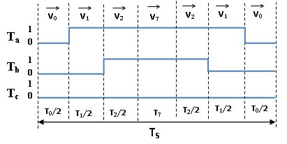
The following Figure 7 shows an example for a pulse timing diagram.
Figure 7. Example for a pulse timing diagram
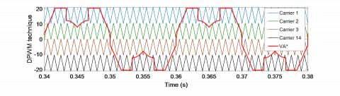
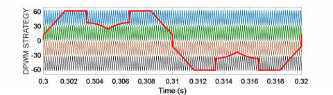
Figure 8 below also shows the reference waves (VA*, VB* and VC*) for the DPWM strategy. With:
$\left[\begin{array}{c}V_{A}^{*} \\ V_{B}^{*} \\ V_{C}^{*}\end{array}\right]=Z C S+\left[\begin{array}{c}V_{A R} \\ V_{B R} \\ V_{C R}\end{array}\right]$ (21)
Figure 8. The reference waveforms and triangular carriers for DPWM, (M=0.9 and fc=1 KHz)
In this section, and in order to verify the efficiency and validity of the proposed system, simulation tests using MATLAB/Simulink have been carried out on a solar power generation with the parameters given in Table 1 software.
Table 1. PV parameters
|
Symbol |
Quantity |
Value |
|
A |
Ideal factor of PV cell |
1.1V |
|
ns |
Cells connected in series |
36 |
|
np |
Number of module in parallel |
1 |
|
Rs |
Series resistance |
0.18 Ω |
|
Rsh |
Shunt resistance |
360.000 Ω |
|
G0 |
Irradiation reference |
1000 W/m2 |
|
T0 |
Temperature reference |
298.15K |
|
k |
Boltzmann’s constant |
1.38e-23J/K |
|
Voc |
Open-circuit voltage |
22,3 V |
|
Iscn |
Nominal short-circuit current |
3.3A |
|
R |
Load resistance |
35 Ω |
|
C2 |
Output capacitor |
2.7µF |
|
C1 |
Input capacitor |
0.27 mF |
|
L |
Inductor |
47 mH |
|
RL |
Resistance of self-inductance |
0.5 Ω |
|
Vd |
Diode’s forward voltage |
1.9V |
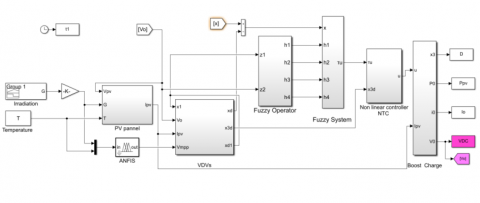
The PV conversion system is associated with a PV/Boost converter, a five level NPC VSI; to fed an inductive resistive load (R=5 Ω and L=50 mH). Figure 9 shows the modeling block of the proposed system.
Figure 9. Simulation model of the proposed system
Figure 10. Simulation model of the DC/DC conversion model
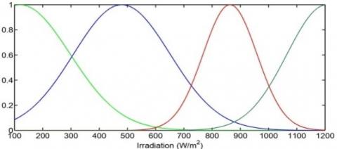
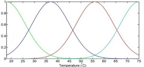
(a) Membership functions of irradiation
(b) Membership functions of temperature
Figure 11. Fuzzy membership functions to generate Vpop
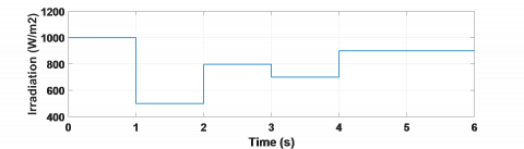
(a) Irradiation profile
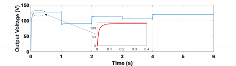
(b) Output voltage of the boost converter
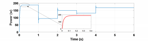
(c) Output power
(d) Duty ratio
Figure 12. Simulation results for various irradiation values
The first part which is devoted to the simulation tests of the PV/DC-DC boost conversion model as shown in Figure 10, as based on the variation of irradiation supposed to be as indicated in the Figure 12a.
The irradiation and temperature are modeled by fuzzy membership functions to get a fuzzy relationship between these parameters and the optimal voltage. These membership functions shown in Figure 11 are optimized using ANFIS algorithm.
The responses of output voltage Vo, output power Po and control signal D provided using the T-S fuzzy controller are shown respectively in Figure 12b, Figure 12c, and Figure 12d.
The output voltage response controlled by the designed T-S fuzzy controller when the boost converter is subject to the Irradiation variation. So, the Irradiation changes from 1000 w/m2 to 500w/m2 and to 800w/m2, 700 w/m2 and then 900 w/m2. We assume that the cell temperature is held constant at 25℃.
As it can be observed, the steady states ideally follow the optimal trajectories and are unaffected by the solar radiation of the cell. This gives the system the ability to extract available solar energy with minimal loss and improve system performance.
In the second part, we will present the simulation results obtained during the tests carried out on the three-phase five-level NPC VSI based on IGBTs/diodes, and using the discontinuous PWM control strategy. The inverter is supplied directly by the PV/Boost converter system. Table 2 below shows the parameters of the DC/AC converter:
Table 2. The parameters of the DC/AC converter
|
PARAMETERS |
VALUE |
|
Input voltage VDC The frequency of the output |
125 V 50 Hz |
|
modulation frequency of DPWM |
6 KHz |
|
The modulation index M |
0.9 |
|
Number of carriers |
4 |
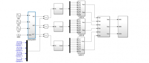
Figure 13 below shows the model scheme of the second part of energy conversion.
Figure 13. Five-level 3-ph. VSI NPC controlled by DPWM strategy
The results obtained are represented by the following Figure 14:
Figure 14. The reference waveforms and triangular carriers for DPWM, (M=0.9 and fc=6 KHz)
This is certainly due to the fact that the reference waveform of this technique has a better distribution of unmodulated areas; four symmetrical saturation sections; each equal 30°, unlike other classic PWM techniques.
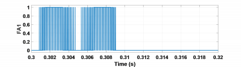
(a) FA1
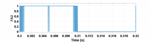
(b) FA2
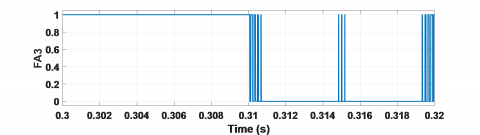
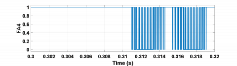
(c) FA3
(d) FA4
Figure 15. Control signals generated by DPWM
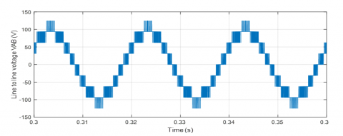
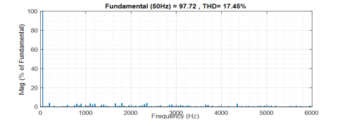
(a) VAB
(b) VAB spectral analysis
Figure 16. Line to line voltage waveform
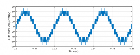
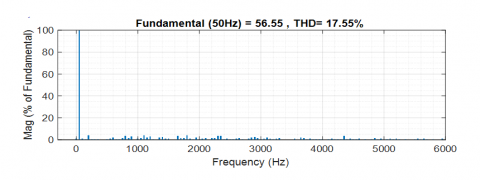
(a) VAN
(b) VAN spectral analysis
Figure 17. Line to neutral voltage waveform
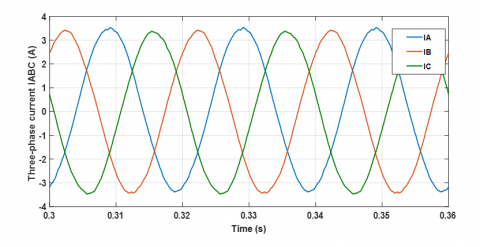
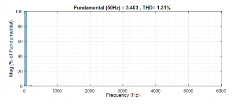
(a) IABC
(b) IABC spectral analysis
Figure 18. Line currents waveform
The Figure 15 presents the control signals (FA1, FA2, FA3 and FA4) for the four transistors of the first half-arm at the top of the inverter. They were generated by discontinuous PWM with a switching frequency of 6 KHz. The other half-arm signals at the bottom are generated in complementarity with those at the top. And therefore the control signals for arms A, B and C are 120° out of phase with each other.
The control signals have areas where there is no switching in both half waves, which is verified by the number of switching per fundamental period, in which the discontinuous technique reduces the number of switching by about 33%.
The Figure 16 shows the shape of the line-to-line voltage at the output of the inverter. We note that this voltage is an alternating wave; it is also in the form of a staircase with five different voltage levels (0, 31.25, 62.5, 93.75 and 125 v). Its harmonic spectrum represents a THD value equal to 17.45% with a fundamental component at the value of 97.72 v.
The Figure 17 represents the shape of the line-to-neutral voltage for phase A of the inverter. The spectral analysis of this voltage gives a harmonic rate of 17.55% with a fundamental component of 56.55 v.
The IABC line currents at the output of the inverter are represented by the Figure 18. They have a sinusoidal shape. They also create a balanced three-phase system at a frequency of 50 Hz. The harmonic spectrum obtained for the line current at a THD value equal to 1.31% with a fundamental component of 3.4 A. This spectrum fully complies with the requirements of the standards (IEEE Std 519-2014) [29], which does not exceed 05%.
According to these results obtained, it is quite clear that the DPWM technique, applied for the five levels NPC three-phase VSI, has excellent performance which generates a reduced number of switching per period, a higher fundamental amplitude and a better spectral quality.
In the present study, a complete simulation system of a three-phase five-level NPC inverter feeding by a PV/Boost converter based on T-SFLC has been proposed using MATLAB/Simulink environment. The simulation results prove that the steady states ideally follow the optimal trajectories and are unaffected by the solar radiation of the PV panel in the first stage conversion (DC/DC).
Inverter topology controlled by a DPWM strategy used in the second stage gives low order harmonics and switching losses are substantially reduced (THDv=17.55%, THDI=1.31% and a reduction by 39.16% of switching losses). Hence, we could obtain the improved performance of the system. So, the results of complete simulation system prove that the association of the two topologies with these controls techniques Contributed to giving an interesting look to the DC/AC conversion stage in the conversion chain.
In the perspectives, we were interested in the realization of this system in a real time and to compare the results obtained with those in experimental.
[1] Tomislav, P. (2020). Handbook of the Sun and Photovoltaic Technologies: Solar Energy. Green Energy and Technology, Springer Nature Switzerland. https://doi.org/10.1007/978-3-030-22403-5
[2] Attoui, H., Behih, K., Bouchama, Z., Zerroug, N. (2021). MPPT for photovoltaic system using adaptive fuzzy backstepping sliding mode control. European Journal of Electrical Engineering, 23(5): 391-399. https://doi.org/10.18280/ejee.230505
[3] Pankaj, S., Rajiv, D. (2022). Maximum power point tracking using adjustable gain based model reference adaptive control. Journal of Power Electronics, 22: 138-150. https://doi.org/10.1007/s43236-021-00336-3
[4] Zhenlong, W., Donghai, L., Yali, X. (2019). A new PID controller design with constraints on relative delay margin for first-order plus dead time systems. Processes, 7(10): 713. https://doi.org/10.3390/pr7100713
[5] Aseem, K., Selva, K.S. (2020). Sliding mode controller for DC to DC converters and performance comparison with conventional PID and FOPID controllers. Journal of Engineering Science and Technology Review, 13(4): 162-172. https://doi.org/10.25103/jestr.134.16
[6] Chandra, S., Durairaj, S., Padmavathi, B.S. (2021). A performance evaluation of a fuzzy logic controller-based Photovoltaic-fed multi-level inverter for a three-phase induction motor. Journal of the Franklin Institute, 358(15): 7394-7412. https://doi.org/10.1016/j.jfranklin.2021.07.032
[7] Xu, S., Chang, L., Shao, R. (2019). Single-phase voltage source inverter with voltage boosting and power decoupling capabilities. IEEE Journal of Emerging and Selected Topics in Power Electronics, 8(3): 2977-2988. https://doi.org/10.1109/JESTPE.2019.2936136
[8] Carrillo-Santos, L.M., Ponce-Silva, M., Reyes-Severiano, Y., Cortés-García, C. (2021). Implementation of the three-phase inverter of medium power for applications in photovoltaic pumping systems avoiding oversizing. European Journal of Electrical Engineering, 23(4): 281-288. https://doi.org/10.18280/ejee.230401
[9] Swamy, D.M., Venkatesan, M., Subbarao, M. (2020). Investigations on three-phase grid-connected inverter using PWM controllers. Journal of Engineering Science and Technology Review, 13(5): 176-182. https://doi.org/10.25103/jestr.135.23
[10] Nagaraju, G.V.V., Rao, G.S. (2020). Three-phase five-level CHB inverter fed induction motor for renewable applications. International Journal of Power Electronics and Drive Systems, 11(3): 1145. https://doi.org/10.11591/ijpeds.v11.i3.pp1145-1152
[11] Zaamouche, F., Saad, S., Hamiche L. (2020). Discontinuous PWM applied for a three-phase five-level CHB inverter fed by PV solar-boost converter. European Journal of Electrical Engineering, 22(2): 153-161. https://doi.org/10.18280/ejee.220209
[12] Khan, A.A., Khan, U.A., Ahmed, H.F., Cha, H., Ahmed, S. (2021). Improved NPC inverters without short-circuit and dead-time issues. IEEE Transactions on Power Electronics, 37(2): 2180-2190. https://doi.org/10.1109/TPEL.2021.3103159
[13] Chan, R., Sangshin, K., Seungdeog, C. (2021). Three phase three level four leg NPC converters with advanced model predictive control. Journal of Power Electronics, 21: 1574-1584. https://doi.org/10.1007/s43236-021-00283-z
[14] Laib, A., Krim, F., Talbi, B., Sahli, A. (2020). A predictive control scheme for large-scale grid-connected PV system using high-level NPC inverter. Arabian Journal for Science and Engineering, 45(3): 1685-1701. https://doi.org/10.1007/s13369-019-04182-1
[15] Angamuthu, A., Sundaram, M., Balaji, V. (2022). Power quality improvement of distribution power networks using capacitor less H bridge inverters for voltage regulation. Journal of Power Electronics, 22: 478-489. https://doi.org/10.1007/s43236-021-00373-y
[16] Huang, S., Guo, X., Wang, R., Mei, Y. (2021). A SVPWM algorithm based on four-switch three-phase inverter for PMSM under the imbalance of bus capacitor voltage. Journal of Power Electronics, 21(12): 1812-1822. https://doi.org/10.1007/s43236-021-00324-7
[17] Gupta, S.K., Khan, M., Singh, O. (2021). Pulse width modulation switching schemes for two-level five-phase voltage source inverter. European Journal of Electrical Engineering, 23(2): 137-142. https://doi.org/10.18280/ejee.230207
[18] Liao, Y., Chen, J.Y., Zhou, Y. (2022). A novel carrier scheme combined with DPWM technique in a ZVS grid-connected three-phase inverter. Electronics (Switzerland), 11(4): 656. https://doi.org/10.3390/electronics11040656
[19] Li, K., Wei, M., Xie, C., Deng, F., Guerrero, J.M., Vasquez, J.C. (2018). Triangle carrier-based DPWM for three-level NPC inverters. IEEE Journal of Emerging and Selected Topics in power Electronics, 6(4): 1966-1978. https://doi.org/10.1109/JESTPE.2018.2812704
[20] Daouadi, R., Ounass, D., Soufi, Y., Metatla, A., Guiza, D. (2020). Real-time implementation of a Takagi-Sugeno fuzzy controller for a DC-DC boost converter. Electrotehnica, Electronica, Automatica (EEA), 68(4): 90-97. https://doi.org/10.46904/eea.20.68.4.11080012.
[21] Palanivel, M., Kaithamalai, U., Parthsarathi, P. (2020). Assessment of IC and ANFIS based MPPT for PV system using super lift boost converter. Fourth International Conference on Electronics, Communication and Aerospace Technology (ICECA). https://doi.org/10.1109/ICECA49313.2020.9297426
[22] Jafari, M., Mobayen, S., Roth, H., & Bayat, F. (2021). Nonsingular terminal sliding mode control for micro-electro-mechanical gyroscope based on disturbance observer: Linear matrix inequality approach. Journal of Vibration and Control, 28(9-10): 1126-1134. https://doi.org/10.1177%2F1077546320988192
[23] Padmavathi, R., Kalaivani, R., Maheswari, P.S., Premkumar, K. (2020). Harmonic distortion analysis of ANFIS controlled PV fed three phase voltage source converter. International Journal of Advanced Trends in Computer Science and Engineering, 9(4): 4650-4656. http://dx.doi.org/10.30534/ijatcse/2020/66942020
[24] Alquicira, A.J., Aldaco, S.E.D., Calleja-Gjumlich, J.H., ClaudioSánchez, A. (2020). Switching angles calculation in multilevel inverters using triangular number sequence – A THD minimization approach. European Journal of Electrical Engineering, 22(1): 49-55. https://doi.org/10.18280/ejee.220106
[25] Safia, Z.B., Allouch, M., Chaabane, M. (2020). Decentralized TS fuzzy control for solar PV powered water pumping system driving by induction motor. European Journal of Electrical Engineering, 22(4-5): 301-311. https://doi.org/10.18280/ejee.224-502
[26] Ounnas, D., Guiza, D., Soufi, Y., Maamri, M. (2021). Design and hardware implementation of modified incremental conductance algorithm for photovoltaic system. Advances in Electrical and Electronic Engineering, 19(2): 100-111. https://doi.org/10.15598/aeee.v19i2.3881
[27] Prasad, D.B.R., Kulkarni, A.D., Ananthapadmanabha, T. (2021). Power quality analysis and its enhancement of microgrid integrated with distributed energy resources. International Journal of Renewable Energy Research (IJRER), 11(4): 1987-1993. https://doi.org/10.20508/ijrer.v11i4.12276.g8355
[28] Roh, C., Kwak, S., Choi, S. (2021). Three phase three level four leg NPC converters with advanced model predictive control. Journal of Power Electronics, 21: 1574-1584. https://doi.org/10.1007/s43236-021-00283-z
[29] 519-2014 - IEEE Recommended Practice and Requirements for Harmonic Control in Electric Power Systems. IEEE Std 519-2014 (Revision of IEEE Std 519-1992), pp. 1-29. IEEE Power and Energy Society, 11 June 2014. https://doi.org/10.1109/IEEESTD.2014.6826459