Dhananjaya Balladka
© 2021 IIETA. This article is published by IIETA and is licensed under the CC BY 4.0 license (http://creativecommons.org/licenses/by/4.0/).
OPEN ACCESS
The companies supplying electric power round the globe are facing various issues related due to the occurrence of fault in the distribution lines. Most of them are investing on the research and development of state-of-art technologies to boost continuous supply of energy to the users. The consumers can be guaranteed of flawless power if it is possible to identify and rectify the faults at the shorter time span than usual. The usual way to identify the fault and fault location is with the aid of man power. This work deals with the design and fabrication of an intelligent system based on the GSM. This system helps in efficient identification of the fault and location of the fault, initiating a message to the respective crew members and the control station and ensures that the technical crew will be able to reach the location very accurately in shorter time and recapitulate power at the earliest. The setup includes a current sensor, Arduino and a GSM module. The system identifies the location of fault and the data regarding the location of fault is efficiently conveyed to the control personnel or monitoring system over GSM. The location of the fault thus obtained is very fine and accurate, and the time needed to identify the location of flaw is greatly reduced.
fault detection, distribution lines, MCB’s, Arduino UNO, GSM
Transmission networks are the vital elements of the power systems bridging both generating stations and consumers with enormous number of conductors. They consist of group of overhead wires spreading in a wide geographical area with varying weather conditions. These networks are distributed on metallic or concrete pillar called “towers”, where the insulating materials isolate the wires from the tower body and from one another with enough spacings with air serving as an insulation medium [1-5]. However, these networks are subjected to a variety of faults periodically. Protection to this network against various faults and weather conditions has emerged to be an interesting field among the researchers.
Various faults can occur in the distribution lines [6, 7] including phase faults or ground faults. Phase faults occur between two conductors and ground faults between conductors and ground. Ground faults [8] among these have emerged to be the dominant ones.
Electrical systems are expanding in size along with the complexity in various segments like power generation, transmission/distribution and load systems. The loss of the electric power to an area for short or long term can be termed as Power Blackout. The faults in the power systems for long duration would lead to a major loss to economy and would reduce the reliability on the structure. An abnormal condition, caused by malfunctioning of equipment’s like transformers, transmission networks, distribution lines due to human errors and environmental conditions can be termed together as electrical fault. These fault causes interruption of electricity flows, equipment damages etc.
Electrical fault would lead to breach of voltages and currents from purported values. During regular operations, power system devices and wires would handle routine current and voltages resulting in safe and normal operation of the system. During the occurrence of fault, the routine values of currents will raise drastically causing damage to circuitry and equipment’s. Detection of Fault with detailed analysis is the need of the hour to design and select apt switchgear accessories, electro-mechanical relays, MCB’s and protective gears. Symmetrical and Asymmetrical faults are the common faults that occur in the electrical power system.
Power failures is normally caused due to strong storms or winds, knocking down a power line, leaving the city in the dark, which in other ways would have made life simpler, comfortable, safe and profitable. Power failure is used by miscreants as an attack method that has come to concern lately because of the hazard due to terrorism. Demanding frameworks depend on electrical energy to work efficiently, and the electrical power depends on the same infrastructures for proper control and communication.
1.1 Motivation
Electricity is a form of energy and we need it for just about everything. Almost all our modern conveniences are electrically powered. The importance of electricity is very critical in everybody’s lives. A blackout for a day will remind us the need and dependency of human lives on electricity. Life would come to a pause without electric energy. The utility companies need to make sure that the power is available when there is a need. As the distribution networks are spread across under various materialistic and topographical conditions, identifying the faults and their location [9] and their status using conventional human labor would be inefficient and sluggish. This rises the need of identifying the fault and its location using unmanned systems. This calls for the need of employing devoted fault location system.
1.2 Data acquired from various sub stations
1) Visited KPTCL 220KV substation,Kavoor
2) MSEZ (Mangalore Special Economic Zone Ltd) 220 KV substation, Bajpe.
Presently distance relays are employed for fault location detection in 220 KV line. These distance relays are not so efficient when it comes for 11 KV lines because in 11 KV lines impedance will be continuously varying as new consumers are going on added.
Fault [10] in an electric circuit can be explained as a condition during which the flow of aberrant Electric current, Due to human errors, adverse weather conditions, malfunctioning of infrastructure causes disruption of current flow, damage to equipment’s and loss of lives. Normally there will be protection provided to electrical equipment’s due to abnormal currents using switch gear protection equipment’s like MCB’s and relays.
2.1 Types of faults
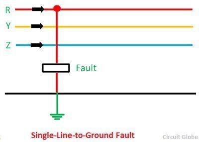
2.1.1 Single line - ground fault
This fault results due to contact of live conductor with the ground or with the neutral wire as shown in Figure 1. Most of the faults appearing in distribution lines are Single Line-Ground fault.
Figure 1. Single line to ground fault
2.1.2 Line-line fault
Figure 2. Line-line fault
This flaw in the circuit occurs due to the wires getting shorted as shown in Figure 2. The reason for this fault is adverse wind. The wind causes the saggy wires to swing and meet each other constituting around 15%-20% of the fault that occurs in the transmission system.
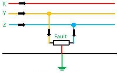
2.1.3. Double line - ground fault
This fault arises when two live wires are shorted as shown in Figure 3 with each other and ground constituting around 10% of the fault in the transmission systems.
Figure 3. Double line - ground fault
2.1.4 Short circuit fault
A short circuit is a condition in which current flows in unexpected path which has very low resistance. It signifies an erratic connection between two nodes of a circuit which are at different potential levels. Short circuit causes damage to electrical equipment’s due to overheating of conductors leading to fire. Almost all the cases of short circuits are unintentional causing both the nodes which are shorted to be at same potential. Short circuited nodes will have no resistance and voltage drops between them. In practical systems the condition of zero resistance exists with high current flow though the wires. The limiting of the current is done by rest of the components of the circuit.
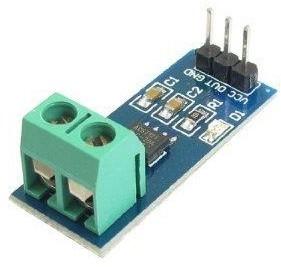
3.1 ACS712 current sensor
A current sensor is an electronic gadget that generates signals relative to the flow of charges (AC or DC) through the sensor. The signal generated by the sensor can be analogues voltage, current or a digital value. This signal produced by the sensor can be used to display the current readings in the ammeter which in turn can be used for analysis in DAS for controlling the system.
Figure 4. ACS712 current sensor
ACS712 is a current sensor as shown in Figure 4 works on the principal of Hall Effect which can measure DC and AC. Being a linear sensor, the chances of error is only 1.5%. The error could still be reduced by programming the sensor more intelligently by introducing standard error for sensor. The sensor gives the proportional DC and AC outputs at the terminals corresponding to the inputs fed. The output depends on the sensitivity coefficient. The ACS712 current sensor is built using linear Hall Effect circuit with a die surrounded by copper wires. The passage of AC or DC through the copper conductors creating magnetic flux which interacts with Hall-effect sensor. This interaction of field with the circuit converts the magnetic field into proportional Alternating or Direct voltage proportional to input current. The output from the sensor is measured using Arduino or any microcontroller-based circuits [11].
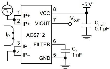
3.2 Pin diagram of ACS712 hall effect current
Figure 5. ACS712 hall effect current sensor
As seen from Figure 5, Pin No. 5 of the IC is ground. Capacitor filter is connected to Pin no. 6. with another terminal of the capacitor grounded. Pin No. 8 is supply terminal via which 5V is connected. The output of the sensor is obtained at Pin no.7. The output voltage from the sensor at pin no. 7 is measured using Arduino.
3.3 Arduino UNO
Arduino [11] is an easily accessible and cheaply available microcontroller that can be programmed and erased without any complicated circuits. Arduino was introduced in the year 2005 and took no time to catch the attention of students and professionals due to its easiness to program and make it interact with real world using sensors and actuators. Arduino UNO is an open license computing platform embedded on a microcontroller board, which is used to build and program electronic gadgets. It also acting as a mini computer to control the outputs of electronic gadgets. Arduino concentrates on making the application more accessible and interactive to its surroundings. The hardware includes of an free license hardware kit designed around an 8-bit Atmel AVR microcontroller or a 32-bit Atmel ARM. The recent boards embed a USB interface, 6 analog input pins and 14 digital I/O pins facilitating the connection of more peripherals.
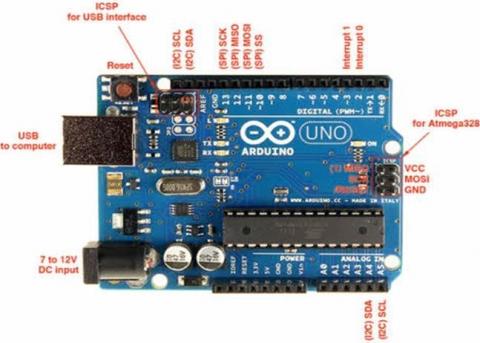
The Arduino Uno in Figure 6 is a microcontroller placed on ATmega328 including 14 digital I/O pins of which 6 are used for PWM outputs, a 16 MHz ceramic resonator, an ICSP header, a USB connection, 6 analog inputs, a power jack and a reset button.
The board is plugged into computer using an USB cable with power supplied from an AC/DC adapter or battery. Arduino Uno Board stands unique from microcontrollers as they don’t utilize the FTDI USB-to-serial driver chip.
Arduino UNO has Atmega16U2 (Atmega8U2 up to version R2) which is programmed like a USB-to-serial converter. Most boards existing are Compatible with third party versions. Arduino Uno version R3 and the Arduino Nano version V3 are the official ones. Both the versions run a 16 MHz Atmel ATmega328P 8-bit microcontroller with 32 KB of flash RAM 14 digital I/O and six analogue I/O. The projects employing Arduino can function independently or can be used to connect with the applications running on system such as Flash, Processing, Max/MSP. Embedded with a ceramic resonator running at a clock frequency of 16 MHz establishes power and communication via USB. The storage capacity for bigger tasks can be easily increased with the addition of micro SD/SD card.
Figure 6. Arduino UNO
3.4 GSM module
Figure 7. GSM module
This device as shown in Figure 7 allows the computer or a processor to communicate with a network. This can either be a mobile or a modem. This module needs a SIM operated over a network range subscribed by the operator. Connection will be established to the computer through serial, USB or Bluetooth connection. This device can be directly connected to a computer or processor with a serial cable through the serial port. A software driver must be installed in the computer in order to establish an effective communication. A GSM modem can be a standard GSM phone with the proper cord and software driver to communicate with the serial port or USB port of the computer. It has more advantages over GSM mobile phones and is usually preferred. GSM modems find a wide variety of applications in vide transaction terminals, supply chain management, security and safety, weather forecasting and remote data logging using GPRS mode.
3.5 Miniature Circuit Breaker (MCB)
An MCB or miniature circuit breaker in Figure 8 is a molded insulating material which encloses an electromagnetic device inside. The MCB functions by switching the circuit i.e. opening the circuitry which is connected during the passage of current higher than the rated value. This switching can be done manually like the normal switches if needed. MCBs are normally time delay tripping devices, where the operating time is controlled by the magnitude of the faulty current. In simple terms MCB protects the devices connected to it during the times of over load in the circuit. MCB’s do not isolate the device during current surges due to transient loads and motor starting. The MCB’s operate in l less than 2.5 Milliseconds for short circuits and might get extended up to 2 seconds in case of overloads.
Figure 8. Miniature Circuit Breaker (MCB)
A commonly used MCB in day to day life is shown in Figure 7. The various versions of MCB’s based on the poles are such as single, double, triple and four pole structures with varying fault current levels. Most of the likely used MCBs are two and three-pole versions which can isolate the fault in a line from the entire circuit. This character of the MCB is helpful in protecting a three-phase motor from single phase faults.
The ratings of MCB’s ranges from 220 V for DC supply and 240/415 for AC supply (single and three- phase) with varying fault current magnitude. Single phase devices have the load current ranging up to 100 A. Modern day MCB’s can be tuned to variable load current while the traditional ones have fixed load and short circuit current MCBs perform a wide variety of functionalities such as controlling local switches, isolating the healthy circuit from the faulty circuit against surge currents and overload currents.
3.6 Single Pole Single Throw (SPST) Switch
A Single Pole Single Throw (SPST) switch as shown in Figure 9 is one which can be given one input and the output produced can be connected only to one output. This implies that this device has a single input and output terminal. This switch serves a simple purpose of turning ON/OFF a circuit. The circuit is said to be on when the switch is ON and the circuit will be OFF when the switch is OFF.
Figure 9. Single pole single throw (SPST) switch
In the context of electrical engineering, a switch can "make" or "break" a circuit, stopping the flow of current or shifting the current from one conductor to other. The operating protocol of a switch is to isolate or rebuild the conducting line in a network. Switches are operated manually based on the input from the sensors.
3.7 ACS 712 Current Sensor
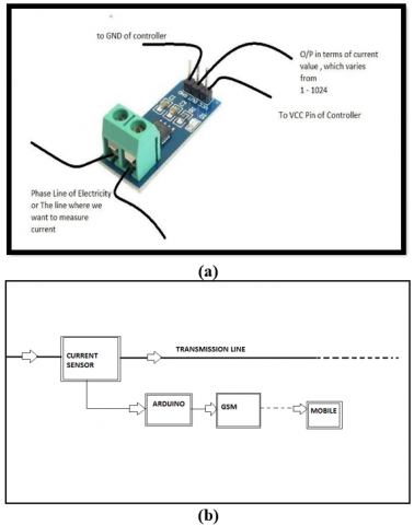
Figure 10. (a). ACS 712 Current Sensor (b). Block Diagram
The current sensor ACS 712 as shown in Figure 10(a) is connected in series with the line as shown in Figure 10(b). Arduino is interfaced with GSM. The occurrence of fault in the line is sensed by the sensor and sends signal to Arduino. The Arduino board sends signal to GSM to send appropriate text message to the corresponding stations.
3.8 Wires
Wires are normally conductors which are cylindrical, Single or many in number stranded together, which is usually manufactured from metals. These are used either to hold mechanical loads or carry electric and communication signals. Wires are manufactured by drawing a molten piece of metal through a hole in a die or draw plate. The size of the wire varies based on the application and is expressed in terms of gauge number. Wires can also include bunches or strand of wires twisted on each other referred as "multi- stranded wire", referred as wire rope in mechanical terms or cable in terms of electricity.
Electrical wiring is normally referred to be a connection between devices and power supply for operation by consumers within an engineered structure or a preferred outdoor location. Wiring includes connecting associated electrical devices such as switches, distribution boards, plug sockets and light accessories with wires but does not include the energy to the instatement.
Detecting the location of fault in distribution line using ACS 712
The current sensor which has the capacity to detect the variation of current in the distribution lines is connected in series with the live wire carrying supply. The sensors are in turn connected to the Arduino kit followed by GSM module.
During the occurrence of fault due to any of abnormal conditions, the current flowing through the line will be shoot up abruptly to the abnormally high value. The sensors connected in series with the line continuously monitors and senses the varying current thereby increasing the output linearly with the current through the sensor. The output of the sensor is connected to the Arduino kit continuously monitors the output of the current sensor. During the occurrence of fault, Arduino board will be able to detect it as the board would be already preset with the threshold value of current under normal operating conditions. As soon as current value through the sensor breaches the preset value, the sensor will produce an output to the Arduino board. The detected fault in Arduino board will be sent as a signal to the GSM module. The received signal will be sent to the crew members and control station by the GSM module. The received data at the receiving station is analyzed in to obtain the accurate location of fault and the probable type of fault.
5.1 Short circuit fault
Figure 11. Short circuit fault
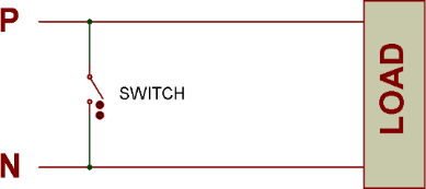
Figure 11 shows a simple load connected to a single-phase supply of 230 volts, 50 Hz supply. A SPST switch is connected across the phase and neutral of the supply. Now to create a short circuit fault, the supply is switched on and the switch is closed. As soon as the switch is closed, very high current flows through the circuit leading to short circuit fault.
5.2 Circuit diagram
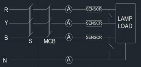
Figure 12. Circuit diagram
Figure 12 shows the circuit diagram of three phase system with sensors connected to all the lines. This sensor can identify fault in any of the lines and report the same to the concerned.
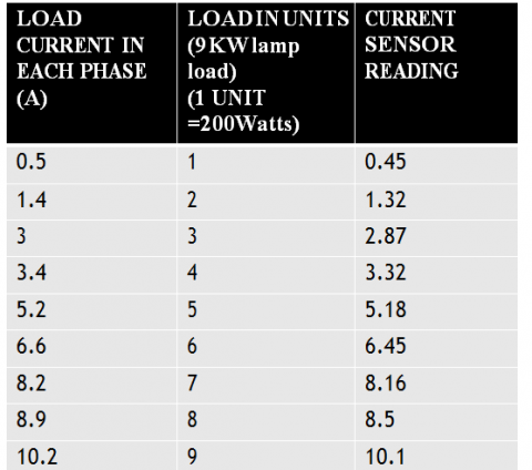
5.3 Phase load test
The Figure 13 attached below reports the output of the sensor varying along with the varying line currents.
Figure 13. Phase load test
5.4 Serial monitoring of current
Figure 14. Serial monitoring of current
The Figure 14 shows the output of the current sensor during normal and faulty conditions. It is observed that at the occurrence of fault the current increases drastically and the system is isolated, and the current flowing after the occurrence of fault is almost zero.
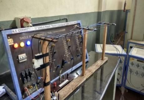
Figure 15 shows the experimental setup used in the laboratory to study the working of the sensors and the Arduino kit. Lamp load is used in all three phases and the fault is induced in one of the phases. As soon as the fault occurs the sensors get activated and send the necessary signal to the Arduino kit. Arduino kit in turn sends signal to the GSM module and the GSM modules sends the co-ordinates to the crew members.
Figure 15. Experimental setup
6.1 Working principle
Figure 16. Flowchart
As seen from the flowchart in Figure 16, during the occurrence of Line to Ground or Line to Line fault, the current flowing through the line hikes to a large value, approximately three times the current that was flowing during the normal operation. The current in the line is monitored with the help of current sensor (ACS712) i.e. hall sensor interfaced with Arduino board continuously with the serial communication technique at a baud rate of 9600 Hz. The current sensor converts the current flowing through it to approximate voltage levels (0 V-5.1 V) which varies linearly depending on the current flowing through it. The Arduino is programmed such that when the current crosses the preset value, it actuates the GSM board (SIM 800) to sends a text message to the operator cell phone. By installing this system to each pole, the fault location can be determined quickly, and the continuity of power supply can be resumed as soon as possible. This technique can also be applied to 11 KV lines by using clamp meters which has higher current rating up to 2000 A instead of hall sensor.
6.2 Text message sent to the maintenance crew
Figure 17 shows the screen shot of the message sent by the GSM module to the crew member after the occurrence of fault. The message displays the location in terms of poles where the fault has occurred which can be attended and power can be restored at the earliest.
Figure 17. Text message sent to the maintenance crew
6.3 Model
Figure 18. Model
Figure 18 shows the working model set up in the laboratory to test the working of the model and its efficiency. The below model works efficiently for all variation of current in the line and messages are being sent to the crew members exactly after 17 Seconds of occurrence of fault. However, the system will be isolated immediately from faulty currents.
Detection of the precise location of the fault was always one area which had always challenged the researchers. The model developed in this project helps in detecting the location of Fault very precisely using GPS module. This project reduces the human effort in walking all along the distribution line to identify the location and reduces the time needed to restore power. The GSM sends the messages to the maintenance crew immediately after the occurrence of fault. The cost of the message depends on the network that will be employed by the Electricity board. The current sensor employed in the project is very efficient in detecting the variation of the current flowing through the line in which it is connected. The current sensors used in the project can withstand large variation of current and temperature.
[1] Chandrashekar. P. (2014). Transmission line fault detection & indication through GSM. International Journal of Recent Advances in Engineering & Technology (IJRAET), 2(5): 28-30.
[2] Milioudis, A.N., Andreou, G.T., Labridis, D.P. (2015). Detection and location of high impedance faults in multi conductor overhead distribution lines using power line communication devices. IEEE Transactions on Smart Grid, 6(2): 894-902. https://doi.org/10.1109/TSG.2014.2365855
[3] Leelakrishnan, S., Ganesharavinth, V., Kalpana, K., Sivaranjani, P., Vijaykumar, S., Shriram, J. (2017). Distribution side fault detection and disconnection using GSM. International Journal of Advanced Research in Electrical, Electronics and Instrumentation Engineering. 6(3). https://doi.org/10.15662/IJAREEIE.2017.0603091
[4] Doshi, D.A., Khedkar, K.B., Raut, N.T., Kharde, S.R. (2016). Real time fault failure detection in power distribution line using power line communication. International Journal of Electrical Engineering, 6(5): 4834-4837. https://doi.org/10.4010/2016.1200
[5] Shunmugam, R., Ashok, K.K., Deebika, D., Manoj, K.K., Mathivanan, A.M (2016). Distribution line fault detection and intimation using GSM. International Journal of Recent Trends in Engineering & Research (IJRTER), 2(4).
[6] Krishnan, V.R., Jose, J., Samad, H., Thomas, A.G., Sreeji, S. (2016). Overhead distribution line fault detection. International Journal of Innovative Research in Electrical, Electronics, Instrumentation and Control Engineering, 4(4): 189-190. https://doi.org/10.17148/IJIREEICE.2016.4445
[7] Lau, S.K., Ho, S.K. (2017). Open-circuit fault detection in distribution overhead power supply network. Journal of International Council on Electrical Engineering, 7(1): 269-275. https://doi.org/10.1080/22348972.2017.1385440
[8] Khavari, S., Dashti, R., Shaker, H.R., Santos, A. (2020). High impedance fault detection and location in combined overhead line and underground cable distribution networks equipped with data loggers. Energies, 13(9): 2331. https://doi.org/10.3390/en13092331
[9] Johns, A.T., Moore, P.J., Whittard, R. (2008). New technique for the accurate location of earth faults on transmission systems. IEE Proceedings - Generation, Transmission and Distribution, 142(2): 119-127. https://doi.org/10.1049/ip-gtd:19951589
[10] Koley, E., Kumar, R., Ghosh, S. (2016). Low cost microcontroller-based fault detector, classifier, zone identifier and locator for transmission lines using wavelet transform and artificial neural network: A hardware co-simulation approach. International Journal of Electrical Power & Energy Systems, 81: 346-360. https://doi.org/10.1016/j.ijepes.2016.02.015
[11] Karalkar, M., Adlok, S., Ramteke, A., Parchake, S., Tawade, R., Manwar, S., Wankhade, S. (2019) Transmission line fault detection using IoT. International Journal of Research in Engineering, Science and Management, 2(3): 128-130.