Muhammad Ishaq* | Yanbo Che | Kifayat Ullah
© 2021 IIETA. This article is published by IIETA and is licensed under the CC BY 4.0 license (http://creativecommons.org/licenses/by/4.0/).
OPEN ACCESS
Matrix converter is an AC-AC direct power converter comprising of an array of bi-directional switches. It does not require an intermediate DC-link and allows sinusoidal output waveforms with varying amplitudes and frequencies. The configuration of these bi-directional switches decides the number of inputs and outputs of the matrix converter. This research uses a direct matrix converter (DMC) as a phase-changing device that can convert a three-phase AC voltage into a 5-phase AC voltage. The DMC is modulated with the model predictive control algorithm. The output of DMC is fed to a five-phase permanent magnet synchronous motor (PMSM). The model predictive current control technique for DMC is carried out by developing a mathematical model of an input filter and PM motor used as a load. The predictive control of DMC results in sinusoidal output current, and it also enables the frequency variation in the output current. This frequency variation is useful in controlling the speed of the motor connected to the load. After controlling the 5-phase motor, the switching frequency regulation is done to observe its effect on the motor's stator current waveforms. Switching frequency regulation helps to limit the unnecessary switching of DMC. We developed a MATLAB-based Simulink model to study PMSM, and detailed results are presented. The results show that switching regulation can significantly reduce the switching frequency without compromising the current waveform quality.
direct matrix converter, model predictive control, switching regulation, PMSM
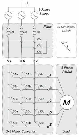
Direct MATRIX Converter (DMC) was first introduced by [1], and the authors proposed a scaler control (SC) technique for its operation. Over the years, DMC has created highlights because of its potential use in a wide range of power system applications such as power electronics and electrical and power engineering. DMC is composed up of bidirectional switches. The switches are arranged in m×n grid configuration [2]. In this m×n grid, m represents the columns, and n represents the number of rows. In other words, the columns denote the number of inputs, and the rows denote the number of outputs of DMC, as shown in Figure 1. Depending on the application, the number of bidirectional switches can be varied. A DMC can be connected in various configurations such as 1×3, 3×1, 3×3, 5×3, and 3×5, and so on. This paper uses a 3×5 configuration.
DMC belongs to a class of power converters that directly transform AC waveforms without requiring an intermediate DC-link stage. In this type of converters, the input side is directly connected to the load side instead of the traditional back-to-back AC-DC-AC converters. In AC-DC-AC converters, the AC is first converted to DC then transformed into AC. Since it is a direct converter, hence the name Direct MC (DMC). DMC is composed of solid-state semiconductor bidirectional switches, for example, a TRIAC. These properties make DMC very compact in design and simple to use. A DMC can generate output voltages with varying amplitudes and frequencies, i.e., an output voltage can be obtained with a different frequency than the input voltage [3].
Additionally, it also generates a sinusoidal output current waveform. It operates with an asymptote unity power factor. Therefore, it has applications in the field of power systems such as reactive power control [4]. DMC allows the transfer of power in both directions, i.e., to and from the load to the electrical grid, making it a regeneration device. For example, if a permanent magnet synchronous machine (PMSM) is connected with a DMC, it can be operated both as a motor and a generator [5].
Due to these characteristics mentioned above, DMC can be widely used as a phase transformation system. DMC can play a vital role in multiphase power generation. Multiphase power generation has several advantages over a conventional 3-phase generation. For example, there is a reduction of phase losses in the multiphase generation system. The output power increases due to high power density. The five-phase power generators are relatively smaller in size compared to three-phase generators [6].
The contemporary structure of the electric power grid is mostly 3-phase; therefore, a phase conversion device is always required when the load requires more than three phases [7]. For example, if a five-phase generator is installed in a power system, then a 3x5 DMC converter can be used to connect it to a 3-phase grid. In the future, when the smart grid is implemented on a larger scale, the use of a 5-phase distributed generator will be widespread. Multiphase distributed generators have many advantages, such as greater fault tolerance capacity, improved long-term reliability, reduced torque ripple, reduced voltage distortion, and the smaller size DC-link. Likewise, a 3×5 DMC converter can be used when a five-phase load is needed to be connected to a 3-phase power supply. A typical example of a multiphase load is a 5-phase motor. It also has many benefits, including a reduction in the amplitude of torque fluctuations and smaller size. It is noted by Ishaq et al. [8] that the size of a five-phase motor is one-third the size of a 3-phase motor. According to the literature [9], the five-phase motor has reduced stator current in each phase without any increase of phase voltage, and this higher power density increases the motor's reliability.
This paper investigates a DMC of three-phase to five-phase (3×5), as shown in Figure 1. Let us represent the voltage by V such that Va denotes input voltage at terminal A and VA represents output voltage at terminal A. This research's primary purpose is to apply the novel switching regulation to a 3×5 DMC that drives 5-phase PMSM [10].
The remaining of the article is organized as follows. Section II presents the system model used in Model Predictive Current Control, Section III deals with DMC's predictive control technique, and Section IV presents the numerical results. Finally, Section V concludes the paper.
Figure 1. Matrix Converter Block Diagram. Source is 3-phase AC, Load is PM synchronous motor. A, B, C, D and E denote output terminals of MC whereas, a, b, and c denote input terminals of MC.
In this section, we present the system model studied in this paper. We explain three sub-models in this section: matrix converter model, load model, and filter model.
2.1 Matrix converter model
Matrix converter (MC) model with 3×5 configuration contains 15 bidirectional switches. These switches can have two states, ON and OFF, represented in binary as 1 and 0. These states can be produced via a gate pulse generated in the controller [11]. Therefore, the total number of switching combinations is 215 = 32768. However, the number of combinations reduces considerably because of the specific constraints listed below [12]. The constraints are:
The first constraint indicates that the short circuit between two or more phases will create over-voltages and result in system damage. Second constraints imply that the load is inductive and its current supply must not be interrupted. Suppose the disconnections occur during the operation of PMSM as described in paper [13]. In that case, the PMSM may draw excessive current, which will create heat in the winding, the ripples in torque are generated, and electronic components may be damaged. The above constraints can be summarized in Eq. (1). Furthermore, based on Eq. (1), as shown in Figure 2, at any given time, only one switch in each column can be turned ON. Here; $S_{A n}$, $S_{B n}$, $S_{C n}$, $S_{D n}$ and $S_{E n}$ represent on/off state of 15 bidirectional switches of DMC [14].
$\begin{array}{r}
\sum_{n=a, b, c} S_{A n}=\sum_{n=a, b, c} S_{B n}=\sum_{n=a, b, c} S_{C n} \\
=\sum_{n=a, b, c} S_{D n}=\sum_{n=a, b, c} S_{E n}=1
\end{array}$ (1)
Initially, the total number of switching combinations in 3×5 DMC is 215=32768, however after applying the above restrictions, the number of switching combinations reduces to 243. Whereas the total number of valid combinations in 5×3 is 125. We can formulate a relation between input and output voltage as shown in Eq. (2). Similarly, we can define the input and output current relation of the 3×5 converter by Eq. (3).
$\left[\begin{array}{c}
V_{a} \\
V_{b} \\
V_{c}
\end{array}\right]=\left[\begin{array}{lllll}
S_{A a} & S_{B a} & S_{C a} & S_{D a} & S_{E a} \\
S_{A b} & S_{B b} & S_{C b} & S_{D b} & S_{E b} \\
S_{A c} & S_{B C} & S_{C C} & S_{D C} & S_{E t}
\end{array}\right]\left[\begin{array}{c}
V_{A} \\
V_{B} \\
V_{C} \\
V_{D} \\
V_{E}
\end{array}\right]$ (2)
$\left[\begin{array}{c}
i_{A} \\
i_{B} \\
i_{C} \\
i_{D} \\
i_{E}
\end{array}\right]=\left[\begin{array}{ccc}
S_{A a} & S_{A b} & S_{A c} \\
S_{B a} & S_{B b} & S_{B C} \\
S_{D a} & S_{D b} & S_{D c} \\
S_{C a} & S_{C b} & S_{C t} \\
S_{D a} & S_{D b} & S_{D c}
\end{array}\right]\left[\begin{array}{c}
i_{a} \\
i_{b} \\
i_{c}
\end{array}\right]$ (3)
Figure 2. Matrix converter switching restrictions
2.2 Load model
The five-phase permanent magnet synchronous machine (PMSM), as shown in Figure 3, is selected as a load for this study. The advantages of using 5 phases instead of 3 phases include low torque ripple, enhanced power distribution, and greater fault tolerance [15]. These characteristics make multiphase machines safer and reliable in applications such as electric vehicles, airplanes, and trains. The output of PMSM is equal to the electric torque produced in PMSM. The torque is denoted by T, and it can be represented by Eq. (5). Similarly, the relationship between stator voltage Vs and stator current is is expressed by Eq. (4) with Ls, Rs. Moreover, E represents stator inductance, resistance, and EMF, respectively.
$V_{S}=L_{S} \frac{d i_{S}}{d t}+R_{S} i_{S}+E$ (4)
$T=E_{A} i_{S A}+E_{B} i_{S B}+E_{C} i_{S C}+E_{D} i_{S D}+E_{E} i_{S E}$ (5)
$\frac{d i_{S}}{d t}=\frac{i_{S}(k+1)-i_{S}(k)}{T_{S}}$ (6)
$i_{S}(k+1)=\left(1-\frac{R_{S} \cdot T_{S}}{L_{S}}\right) i_{S}(k)+\left(\frac{V_{S}(k)-E(k)}{L_{S}}\right) T_{S}$ (7)
Stator current derivative approximation is expressed by Eq. (6). Substituting Eq. (4) in Eq. (6) results in Eq. (7), and it represents the expression for the prediction of stator current with sampling time Ts in model predictive current control technique.
Figure 3. Simplified model of PM motor
Here, $i_{S}(k+1)$ is future or predicted value of current for the sampling interval k+1 for different values of voltage V, whereas the output voltages V(k) are calculated for all valid MC switching states [16].
2.3 Low pass filter model
A passive low-pass input filter is used at the source side of DMC to compensate for the ripples and distortions in the input current and output voltage [17]. The switching of DMC causes these distortions. In the input filter model, the relationship of resistance Rf and inductance Lf with filter voltage Vf is defined by Eq. (8) whereas, the relationship between capacitance Cf and filter current if is defined by Eq. (9).
$V_{f}=R_{f} i+L_{f} \frac{d i}{d t}+V_{i n}$ (8)
$i_{f}=C_{f} \frac{d V_{i n}}{d t}+i_{i n}$ (9)
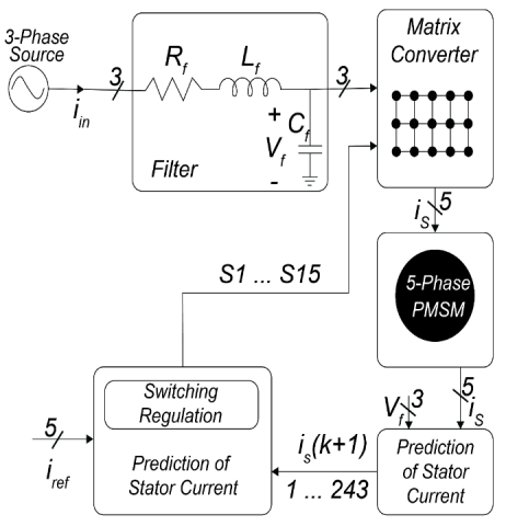
In this section, the model predictive current control (MPCC) algorithm for DMC is presented. First, the control technique, along with the block diagram, is presented. Then, the switching regulation and optimization of the control algorithm are presented. Finally, the frequency conversion capability of DMC is discussed.
3.1 Control technique
Model predictive current control uses dynamic empirical models to predict future events and carries out control actions according to predictions. The key feature of an MPCC is that it allows the cost function to be optimized in the present time-step while keeping into account the future time-steps. MPCC allows the optimization of multiple control parameters simultaneously [18].
Figure 4. Block diagram of model predictive current control technique for matrix converter
Figure 5. MPCC flow chart
A block diagram of the MPCC technique is presented in Figure 4. The PMSM is used as the load, and its model and the model of the input filter are used to predict future values of current for the five-phase stator for all 243 valid switching combinations of a 3×5 DMC. Based on these predicted values, we minimize the cost function $g$ as expressed in Eq. (10). The flow chart of the MPCC algorithm is shown in Figure 5. According to the flow chart, the actual circuit parameters are measured and fed to the model predictive control block to predict output current. Subsequently, an optimal switching combination is selected by calculating g for all 243 switching combinations and then is applied to the DMC in the next sampling instant. The expression of the cost function for this control technique is presented in Eq. (10). Here, iref is the reference current and $i_{S}^{p}$ is the predicted stator current [19].
The cost function tracks how the stator current follows the reference current. Switching combinations that produce the smallest difference between $i_{S}^{p}$ and iref is selected. Eq. (10) is further elaborated in Eq. (11).
$g=\left|i^{r e f}-i_{S}^{p}\right|$ (10)
$g=\left|i_{\alpha}^{\text {ref }}-i_{S \alpha}^{p}\right|+\left|i_{\beta}^{\text {ref }}-i_{S \beta}^{p}\right|$ (11)
Here, $i_{\alpha}^{\text {ref }}$, $i_{\beta}^{\text {ref }}$, $i_{S \alpha}^{p}$, and $i_{S \beta}^{p}$ are the real part of the reference current, the imaginary part of the reference current, the real part of the stator predicted current, and the imaginary part of the stator predicted current, respectively. The Cost function calculation is done in the alpha-beta (αβ) reference frame. The (αβ)-transform is a mathematical transformation used to simplify multiphase quantities into two parts, one is real, and another is imaginary. The (αβ)-transform projects multiphase quantities onto a stationary reference frame with two axes [20].
3.2 Switching frequency regulation
One of the main advantages of the MPCC technique is the possibility of including multiple cost-function tracking parameters to achieve additional objectives such as the switching frequency regulation (SFR), torque, and flux control. Apart from the output current control, various researchers have incorporated direct control of input current waveform to achieve high power factor operation [21]. DMC switching affects the input current and output voltage waveforms. Higher switching frequency increases the total harmonic distortion (THD) in the waveforms but results in sinusoidal output current. Low switching frequency decreases THD in the input waveforms but results in less sinusoidal output current with high THD. The main aim of the SFR is to reduce switching losses by limiting the number of commutations. SFR is achieved by penalizing those switching states that involve a higher number of commutations per sampling time [22].
For this purpose, a secondary parameter p, as expressed in (12), is included in the cost function g to regulate the switching [23]. Secondary parameter p is defined as "the total sum of the change in the switching states of all individual switches of the matrix converter." Eq. (12) can be further elaborated in Eq. (13). It is evident from the expression that we ideally require a switching pattern that forces fewer switches to change their states. For example, suppose we have 15 bi-directional switches in 3×5 MC. In that case, we want the least number of switches to change their states across two sampling instances. In Eq. (12) and Eq. (13), k is the current sampling instant of the simulation, while k-1 is the previous sampling instant [24, 25].
Therefore, a minimum value of p is selected during the cost function evaluation. As a result, our cost function is modified as expressed in Eq. (14). Here, $g$ represents the combined cost function, A is the weighting factor, and p is a secondary parameter [26].
$p=\sum\left|S_{m n}(k-1)-S_{m n}(k)\right|$ (12)
$\begin{aligned}
p=\mid S_{A a} &(k-1)-S_{A a}(k) \mid \\
&+\left|S_{A b}(k-1)-S_{A b}(k)\right| \\
&+\left|S_{A c}(k-1)-S_{A c}(k)\right| \\
&+\left|S_{B a}(k-1)-S_{B a}(k)\right| \\
&+\left|S_{B b}(k-1)-S_{B b}(k)\right| \\
&+\left|S_{B c}(k-1)-S_{B c}(k)\right| \\
&+\left|S_{C a}(k-1)-S_{C a}(k)\right| \\
&+\left|S_{C b}(k-1)-S_{C b}(k)\right| \\
&+\left|S_{C c}(k-1)-S_{C_{C}}(k)\right| \\
&+\left|S_{D a}(k-1)-S_{D a}(k)\right| \\
&+\left|S_{D b}(k-1)-S_{D b}(k)\right| \\
&+\left|S_{D c}(k-1)-S_{D c}(k)\right| \\
&+\left|S_{E a}(k-1)-S_{E a}(k)\right| \\
&+\left|S_{E b}(k-1)-S_{E b}(k)\right| \\
&+\left|S_{F c}(k-1)-S_{E c}(k)\right|
\end{aligned}$ (13)
$g^{\prime}=g+A \cdot p$ (14)
The relation of the secondary parameter $p$ with the best of the cost function is controlled with the weighting factor A. The larger value of A will increase the importance of p resulting in more aggressive SFR. However, greater SFR results in higher THD, as discussed before. Therefore, a balance between the value of A and the acceptable level of THD is required [27].
3.3 Frequency conversion
DMC, as discussed previously, can be used as a cyclo-converter. MPCC technique allows efficient frequency conversion capabilities. Source frequency can be increased or decreased depending upon the application's requirements. As shown in Figure 6, the MPCC technique of DMC supports the variable frequency, frequency, and amplitude of the reference current, along with the nature of the load model determines the frequency of the output current. The frequency of the reference current can either be set lower or higher depending upon the application. Figure 6(b) shows that the SFR visibly reduced switching compared to (a). Moreover, the output current's quality is also not affected drastically, as shown in Figure 6(d).
The frequency becomes an essential parameter for the machine's speed when PMSM is used as DMC load. It determines the machine's synchronous speed, and it is useful in PMSM because the speed is independent of the load. Synchronous speed is the synchronization of the rotation of the shaft with the supply current. The precision of speed and position control of the permanent magnet machine is superior. The expression for synchronous speed is given by Eq. (15). Here, f is the line frequency of the supply current, and P is the number of poles. This speed is measured in revolutions per minute (RPM) [28].
$\text { Synchronous Speed }=120 \frac{f}{P}$ (15)
Simulations for this research are done in MATLAB/Simulink using Simscape library. The simulation parameters are listed in Table 1. The three-phase source is connected at the MC input, five-phase PMSM is connected at the MC output. This simulation aims to observe the effect of switching regulation on the three-phase output current waveform as well as the speed control of PMSM using the frequency variation property of DMC.
Figure 7(a) shows the 3-phase MC supply voltage without switching frequency regulation (SFR), hence the weighting factor A is zero, and Figure 7(b) shows 3-phase supply voltage with active SFR. It is observed that the input voltage is unaffected when the value of A is increased. On the other hand, the value of A directly affects the input current. Input current is distorted when A is increased from A =0 to A =0.01 as shown in Figure 7(c) and (d), respectively. Figure 7(e) and (f) show the THD spectrum of the input current. THD increases from 40% to 67% when A is set to 0.01.
Table 1. Simulation parameters
|
Parameter |
Symbol |
Value |
|
|
Solver |
|
ODE5 |
|
|
Sampling Time |
Ts |
1×10⁻⁶s |
|
|
Input Voltage |
Va |
220 V |
|
|
Reference Current |
Iref |
9 A |
|
|
Weighting Factor |
A |
0.01 |
|
|
Input Filter |
Resistance |
Rf |
1 Ω |
|
Inductance |
Lf |
450×10-6 H |
|
|
Capacitance |
Cf |
22×10-6 F |
|
|
PMSM |
Phases |
|
5 |
|
Poles |
P |
8 (4 pairs) |
|
Figure 6. DMC output at 50 Hz, 100 Hz and 200 Hz. (a) Output Voltage without Switching Regulation, notice the increase in switching when output frequency is increased; (b) Output Current without switching regulation; (c) Output Voltage with switching regulation; (d) Output Current with switching regulation.
Figure 7. Effect of weighting factor A on DMC output current, (a) Input Voltage at weighting-factor A=0, (b) Input Voltage at A=0.01, (c) Input Current at A=0, (d) Input Current at A=0.01, (e) THD spectrum of input Current at A=0, and (f) THD spectrum of Input Current at A=0.01.
Figure 8. Effect of variation of weighting factor A on DMC output voltage, List from top: (a) MC output voltage at weighting-factor A=0, (b) Output Voltage THD spectrum at A=0, (c) MC output voltage at weighting-factor A=0.01, (b) Output Voltage THD spectrum at A=0.01.
Figure 8(a) shows the output voltage of MC at the weighting factor A=0 of SFR, while Figure 8(b) presents its THD spectrum. Similarly, Figures 8(c) and (d) show MC output voltage at A=1 and its THD spectrum. Switching-regulation has optimized the switching frequency by reducing the switching count. Comparing output voltage waveforms shows significantly reduced switching, and THD has decreased by almost 5%.
Figure 9 shows the total switching count (SC) of MC in 0.04 seconds. It can be observed that SC is almost 15000 when there is no active SFR. SC reduces considerably to around 3000 when the weighting factor is set to A=0.01. SC further reduces to 1000 when A=0.02. It is found that the value of weighting factor A=0.01 is sufficient because a further increase in its value affects the sinusoidal shape of the output current waveform and introduces significant distortion.
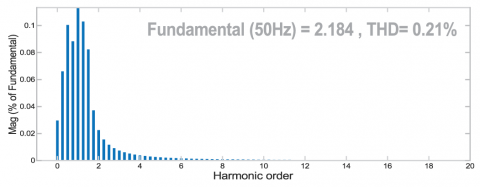
Figure 10(a) shows the stator current of the 5-phase PM motor, (b) shows the speed of the motor in RPM, and (c) shows the electromagnetic torque along with the reference torque. The supply voltage frequency is 50 Hz, and the motor has eight poles. In response to the increase in torque, as shown in Figure 10(c), the amplitude of the stator current also increases to maintain the speed at 750 RPM, as shown in Figure 10(a). Similarly, the speed increases from 0 to maximum in 0.1 seconds. Moreover, the THD spectrum of stator current is presented in Figure 11. The total harmonic distortion is around 0.21%, which is acceptable.
Figure 9. Switching frequency at A=0 (blue), A=0.01 (red), and A=0.02 (yellow)
Figure 10. PMSM parameters, (a) Stator Current, (b) Speed in RPM and (c) Reference Torque (blue) and Motor Torque (Orange)
Figure 11. THD spectrum of PMSM stator current
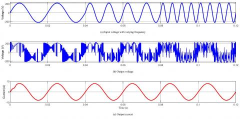
Finally, Figure 12 shows the output current and DMC voltage when the input voltage frequency varies significantly. Here three different input voltage frequencies are applied, e.g., 50 Hz, 100 Hz, and 200 Hz. Despite the varying input frequency, the output current remained stable at 50 Hz with a smooth waveform. This property makes the DMC an attractive choice for variable speed wind energy generation (WEG) [29]. The PMSM based WEG enables the turbine's operation at its maximum power point over a wide range of wind speeds. These WEG systems are optimum because they do not require brushes or a gearbox that wears. Electricity generated by PMSM has variable amplitude and frequency. It requires extra power converters to match the frequency and amplitude of the main grid, which are to run conventional loads [30].
Furthermore, the PMSMs are increasingly used in marine propulsion systems, electric vehicles, and the aerospace industry. These applications would require an MC controller that is compact and has high efficiency and reliability [31]. MPCC needs high sampling frequency to ensure accurate tracking of the control variables, leading to increased computational effort and requiring high-cost controllers to implement MPCC on the industrial scale. Likewise, large inductor and capacitor filters are essential to remove the current and voltage harmonics [32]. These issues must be addressed to increase the use of matrix converter in the real world.
Moreover, DMC control schemes achieve good performance, but they introduce substantial common-mode voltage (CMV) at the motor end. High CMV creates leakage and bearing currents which reduce the motor life and degrade the system reliability. Therefore, control schemes must be designed to mitigate the CMV for DMC fed drive systems [33].
Figure 12. DMC output voltage and current when voltage is of varying frequency
We presented the control of 5-phase PMSM via a 3×5 Direct Matrix converter in this paper. The model predictive current control technique is used to modulate a 3×5 DMC. A 3-phase voltage is transformed into a 5-phase voltage with DMC. Predictive control of DMC resulted in a sinusoidal supply of current for the load. Regulation of switching frequency is achieved using a 3×5 matrix converter. The simulation results consistently show that the process of switching regulation is effective in reducing switching of the bidirectional switches and. Switching regulation allowed the losses to be considerably reduced. A 3×5 DMC is useful for running 5-phase loads such as PM and IM motors. It can also be used as a phase conversion device for the interconnection of 5-phase generators to 3-phase grid systems.
This work was supported by the National Key Research and Development Program of China under Grant 2018YFB0905803.
[1] Alesina, A., Venturini, M.G.B. (1989). Analysis and design of optimum-amplitude nine-switch direct AC-AC converters. IEEE Transactions on Power Electronics, 4(1): 101-112. https://doi.org/10.1109/63.21879
[2] Leubner, M., Remus, N., Haase, J., Hofmann, W. (2018). Collector-emitter voltage-based one-step commutation for direct three-level matrix converter. 20th European Conference on Power Electronics and Applications (EPE'18 ECCE Europe), Riga, Latvia, pp. 1-9.
[3] Li, G.B., Hu, J.F., Li, Y.D., Zhu, J.G. (2019). An improved model predictive direct torque control strategy for reducing harmonic currents and torque ripples of five-phase permanent magnet synchronous motors. IEEE Transactions on Industrial Electronics, 66(8): 5820-5829. https://doi.org/10.1109/TIE.2018.2870359
[4] Basri, H.M., Mekhilef, S. (2016). Model predictive torque and flux control of induction motor fed by three level indirect matrix converter with unity power factor strategy. IEEE 8th International Power Electronics and Motion Control Conference, Hefei, China, pp. 2557-2563. https://doi.org/10.1109/IPEMC.2016.7512701
[5] Munuswamy, I., Wheeler, P.W. (2017). Third method for regenerative braking in matrix converter drive: More electric aircraft. Innovations in Power and Advanced Computing Technologies (i-PACT), Vellore, India, 2017, pp. 1-6. https://doi.org/10.1109/IPACT.2017.8244884
[6] Dabour, S.M., Abdel-Khalik, A., Ahmed, S., Massoud, A. (2016). Performance of a three-to-five matrix converter fed five-phase induction motor under open-circuit switch faults. IEEE Symposium on Computer Applications & Industrial Electronics, Penang, Malaysia, pp. 159-164. https://doi.org/10.1109/ISCAIE.2016.7575056
[7] Levi, E. (2015). Advances in converter control and innovative exploitation of additional degrees of freedom for multiphase machines. IEEE Transactions on Industrial Electronics, 63(1): 433-448. https://doi.org/10.1109/TIE.2015.2434999
[8] Ishaq, M., Afzal, M.H., Waqar, M. (2020). Model predictive control of 3× 5 and 5× 3 bidirectional matrix converter. 17th International Conference on Electrical Engineering/Electronics, Computer, Telecommunications and Information Technology (ECTI-CON), Phuket, Thailand, pp. 443-446. https://doi.org/10.1109/ECTI-CON49241.2020.9158071
[9] Qu, J.G., Xu, J., Wang, L.N., Hui, Y.N. (2018). Research on the modulation and control of multilevel matrix converter. The Journal of Engineering, 2018(13): 614-621. https://doi.org/10.1049/joe.2018.0058
[10] Hossam, H.H., Youssef, A.R., Mohamed, E.M. (2020). Optimal power extraction control schemes for five-phase PMSG based wind generation systems. Engineering Science and Technology, an International Journal, 23(1): 144-155. https://doi.org/10.1016/j.jestch.2019.04.004
[11] Rivera, M., Wheeler, P., Olloqui, A., Khaburi, D.A. (2016). A review of predictive control techniques for matrix converters - Part II. 2016 7th Power Electronics and Drive Systems Technologies Conference (PEDSTC), Tehran, Iran, pp. 589-595. https://doi.org/10.1109/PEDSTC.2016.7556926
[12] Kumar, A., Sadhu, P.K., Mohanta, D.K., Reddy, M.J.B. (2018). An effective switching algorithm for single phase matrix converter in induction heating applications. Electronics, 7(8): 149. https://doi.org/10.3390/electronics7080149
[13] Li, G.D., Zhao, Y.X., Li, B. (2020). Open-circuit fault-tolerant control of five-phase permanent-magnet synchronous motor using control variable method. International Conference on Electrical Machines (ICEM), Gothenburg, Sweden, pp. 2132-2138. https://doi.org/10.1109/ICEM49940.2020.9270955
[14] Gulbudak, O., Santi, E. (2015). A predictive control scheme for a dual output indirect matrix converter. IEEE Applied Power Electronics Conference and Exposition (APEC), Charlotte, NC, USA, pp. 2828-2834. https://doi.org/10.1109/APEC.2015.7104751
[15] Pandit, J.K., Aware, M.V., Nemade, R.V., Levi, E. (2016). Direct torque control scheme for a six-phase induction motor with reduced torque ripple. IEEE Transactions on Power Electronics, 32(9): 7118-7129. https://doi.org/10.1109/TPEL.2016.2624149
[16] Li, J.Y., Cui, M.T., Du, T.Q., Sun, C.J., Huang, X.J. (2019). Modeling and analyzing an optimal control method for parallel multi-matrix converter systems in intelligent micro-grid. IEEE International Conference on Sustainable Energy Technologies and Systems (ICSETS), Bhubaneswar, India, pp. 103-108. https://doi.org/10.1109/ICSETS.2019.8744799
[17] Wang, R.T., Wang, X., Liu, R.T., Zhang, J.W., Mu, X.J. (2018). Generalized double line voltage synthesis strategy for three-to-five phase matrix converter. IET Power Electronics, 11(5): 895-901. https://doi.org/10.1049/iet-pel.2017.0487
[18] Kali, Y., Rodas, J., Gregor, R., Benjielloun, K., Doval-Gandoy, J., Goodwin, G. (2018). Speed control of a five-phase induction motor drive using modified super-twisting algorithm. International Symposium on Power Electronics, Electrical Drives, Automation and Motion (SPEEDAM), Amalfi, Italy, 938-943. https://doi.org/10.1109/SPEEDAM.2018.8445404
[19] Wang, R.T., Wang, X., Liu, C., Gao, X.W. (2018). A duty cycle space vector modulation strategy for a three-to-five phase direct matrix converter. Energies, 11(2): 370. https://doi.org/10.3390/en11020370
[20] Andraž, R., Mitja, N., Henrik, L., Peter, Z., Danijel, V. (2019). Trendi v razvoju močnostne elektronike za vodenje električnih strojev. Elektrotehniški vestnik, letnik 86, številka 5, str. 237-247. URN:NBN:SI:DOC-3RV9JNPF from http://www.dlib.si
[21] Lei, J.X., Feng, S., Wheeler, P., Zhou, B., Zhao, J.F. (2020). Steady-state error suppression and simplified implementation of direct source current control for matrix converter with model predictive control. IEEE Transactions on Power Electronics, 35(3): 3183-3194. https://doi.org/10.1109/TPEL.2019.2928874
[22] Vargas, R., Rodriguez, J., Rojas, C.A., Rivera, M. (2014). Predictive control of an induction machine fed by a matrix converter with increased efficiency and reduced common-mode voltage. IEEE Transactions on Energy Conversion, 29(2): 473-485. https://doi.org/10.1109/TEC.2014.2299594
[23] Rahman, K., Iqbal, A., Al-Hitmi, M.A., Dordevic, O., Ahmad, S. (2019). Performance analysis of a three-to-five phase dual matrix converter based on space vector pulse width modulation. IEEE Access, 7: 12307-12318. http://dx.doi.org/10.1109/access.2019.2892514
[24] Booin, M.B., Cheraghi, M. (2019). THD minimization in a five-phase five-level VSI using a novel SVPWM technique. 10th International Power Electronics, Drive Systems and Technologies Conference (PEDSTC), Shiraz, Iran, pp. 285-290. https://doi.org/10.1109/PEDSTC.2019.8697810
[25] Siami, M., Khaburi, D.A., Rodriguez, J. (2018). Simplified finite control set-model predictive control for matrix converter-fed PMSM drives. IEEE Transactions on Power Electronics, 33(3): 2438-2446. https://doi.org/10.1109/TPEL.2017.2696902
[26] Wu, X.S., Song, W.S., Xue, C. (2018). Low-complexity model predictive torque control method without weighting factor for five-phase PMSM based on hysteresis comparators. IEEE Journal of Emerging and Selected Topics in Power Electronics, 6(4): 1650-1661. https://doi.org/10.1109/JESTPE.2018.2849320
[27] Tereshkin, V.M., Grishin, D.A., Makulov, I.A. (2018). A comparative analysis of the efficiency of three- and five-phase self-controlled synchronous motors. Russian Electrical Engineering, 89: 343-349. https://doi.org/10.3103/S1068371218050103
[28] Debour, S.M., Abdel-Khalik, A.S., Ahmed, S., Massoud A.M., Allam, S.M. (2018). Common-mode voltage reduction for space vector modulated three- to five-phase indirect matrix converter. International Journal of Electrical Power & Energy Systems, 95: 266-274. https://doi.org/10.1016/j.ijepes.2017.08.020
[29] Siami, M., Khaburi, D.A., Rivera, M., Rodríguez, J. (2017). An experimental evaluation of predictive current control and predictive torque control for a PMSM fed by a matrix converter. IEEE Transactions on Industrial Electronics, 64(11): 8459-8471. https://doi.org/10.1109/TIE.2017.2703658
[30] Rajendran, S., Govindarajan, U., Sankar, D.S.P. (2014). Active and reactive power regulation in grid connected wind energy systems with permanent magnet synchronous generator and matrix converter. IET Power Electronics, 7(3): 591-603. https://doi.org/10.1049/iet-pel.2013.0058
[31] Yousefi, B., Soleymani, S., Mozafari, B., Gholamian, S.A. (2017). Speed control of matrix converter-fed five-phase permanent magnet synchronous motors under unbalanced voltages. Energies, 10(10): 1509. https://doi.org/10.3390/en10101509
[32] Saeed, M.S.R., Song, W.S., Yu, B., Wu, X.S. (2020). Low-complexity deadbeat model predictive current control with duty ratio for five-phase PMSM Drives. IEEE Transactions on Power Electronics, 35(11): 12085-12099. https://doi.org/10.1109/TPEL.2020.2983048
[33] Lei, J.X., Feng, S., Zhou, B., Nguyen, H.N., Zhao, J.F., Chen, W. (2020). A simple modulation scheme with zero common-mode voltage and improved efficiency for direct matrix converter-fed PMSM drives. IEEE Journal of Emerging and Selected Topics in Power Electronics, 8(4): 3712-3722. https://doi.org/10.1109/JESTPE.2019.2934730