Ihssane Chtouki* | Patrice Wira | Malika Zazi | Ali Yahia Cherif | Sami Meddour
© 2020 IIETA. This article is published by IIETA and is licensed under the CC BY 4.0 license (http://creativecommons.org/licenses/by/4.0/).
OPEN ACCESS
In order to better adapt to the variation in solar irradiation and to improve the efficiency of the photovoltaic generator, i.e. to maximize the power delivered to the grid. Several criteria’s for optimizing the efficiency of the photovoltaic system have been applied. Among them, the algorithms for tracking the optimal operating point of the photovoltaic panels that called Maximum Power Point Tracking (MPPT). In this article, a PV generator (GPV) has been connected to the power grid, as a result, direct consequence is in the deterioration of the voltage wave and thus the quality level of the energy supplied to the consumers. To overcome these problems of harmonic pollution, active power filtering is proposed as an efficient solution to improve grid power quality. This paper therefore proposes to examine the characteristics of an association between a photovoltaic generator (PVG) that aims at injecting active power into the electrical grid and a parallel active filter that has the task of eliminating disturbances present in this grid. The theory of the two-phase method with Adaline harmonic extraction is applied for the extraction of the reference currents according to the DQ reference frame. Finite set mode predictive current control (FS-MPCC) applied on PAF has been proposed in order to compensate undesirable harmonic, and reactive power resulting from a non-linear load. A Global Maximum Power Point Tracking (GMPPT) algorithm based Adaline method has been suggested for extracting power from PVG. A simulation under Matlab/Simulink of the global system proves the robust performance capability of the suggested Adaline Neuro-Predictive (ANP) control to simultaneously provide harmonic current compensation, power factor correction and solar power energy injection into the grid.
photovoltaic generator (PVG), parallel active power filter (PAF), power grid, GMPPT, Finite set mode predictive current control (FS-MPCC), Adaline Neuro-Predictive (ANP)
Photovoltaic (PV) solar energy has been considered currently among the most powerful sources of renewable energy. PV systems are not restricted only as power producers active through the electricity grid, but also help to improve the quality of energy. In the past, distribution networks behaved as passive elements in which power flows unidirectionally from the source substation to the end consumers. Due to the insertion of Photovoltaic Generators, power flows and voltages are impacted not only by loads but also by sources. As a result of these technical specificities of photovoltaic systems, the connection of PV systems to the grid can have a significant impact on the operation of the grid. In the proposed context, where the levels of power produced vary in large proportions, the rapid growth in the use of non-linear loads and their generalization in power grids tends to degrade the quality of electrical energy, mainly by injecting harmonic currents into the grid. The direct consequence is the deterioration of the voltage wave and thus the level of quality of the energy supplied to the consumers. To overcome these problems of harmonic pollution, active power filtering proves to be an adequate and efficient solution. The presence of power electronic interfaces can inject switching harmonics to the grid if the inverters are not equipped with efficient filters and robust control. Current inverters still contribute to the increase of current harmonics because they usually operate at reduced power, so the THDs are more important. For this purpose several researchers are contributing to the improvement of the quality of Energy. Azzam-Jai and Ouassaid [1] discuss a multifunctional photovoltaic grid-based shunt active power filter (PV-SAPF) using a neural control strategy for diphases currents. the control strategy aims to use the PV-SAPF for dampening harmonic currents, controlling the DC link voltage and compensating the reactive power. The paper [2] presents the modeling of a PV inverter operating as an active filter (AF). The control of the PV inverter is based on a PI controller applied in the dq reference frame to control and extract harmonic currents. The principle of this work is based on the compensation of the fundamental reactive power and the non fundamental distortion power due to the non-linear loads connected in the local grid. Serghine et al. [3] describe a combination of a grid-connected PV system with a parallel active filter. In this work, the authors propose a classical control strategy based on the instantaneous p-q theory used to control the voltage source inverter. The model aims simultaneously to provide active and reactive power to the grid. Two operating controls are used to control the grid-connected photovoltaic system [4]. The first one is the current control that regulates the current in the PCC (point of common coupling). The second one is the voltage control which is used to obtain the output voltage of the PV. The main drawback in this method that the maximum power point will rapidly follow the evolution of the PV grid and in the case where there is a problem in the DC bus regulation we can't have a better tracking. In this work PV architecture with a tidy chopper structure and a single inverter was adopted to ensure the PV-grid combination. It should be remembered that this architecture allows, on the one hand, flexibility of the MPPT control and, on the other hand optimization of the installation cost and the number of interactions between the grid and the PV installation since we are limited only to a single DC/AC converter for connection to the grid. This later function both as a PV-grid interface system and as a PAF.
The contributions in this article are:
- The control applied to the DC-DC step-up converter with the implementation of an MPPT algorithm into a PV grid-interconnected system.
-The control applied to the inverter using a PAF.
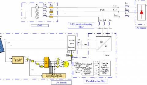
Figure 1. Complete configuration model of the photovoltaic generator - Parallel Active Filter (PVG-PAF)
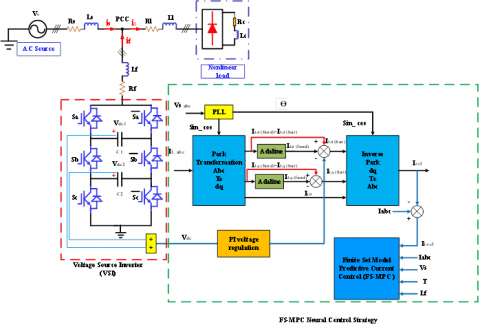
The Synchronous Reference Frame (SRF) theory combined with the Artificial Neural Network (ANN) using the Adaline method is applied to extract the reference currents, while a PI regulator is proposed for controlling the DC capacitor voltage after the extraction of the maximum power. For the generation of the control signal, the Finite State Mode Predictive Current Control (FS-MPCC) is applied to the PAF using two levels Voltage Source Inverter (2l-VSI). For extracting the power from the PVG, an Adaline-type MPPT algorithm is used which allows increasing the efficiency of the system. The combination PVG-PAF composed of a PVG [5], a DC-DC boost converter, a DC link capacitor, a 3-phase DC-AC inverter, a filter inductor, a grid and a non-linear load like is shown in Figure 1. This system is verified under MATLAB/Simulink and as results, the simulation is confirmed. In addition, both steady-state and transient characteristics are thoroughly analyzed for each of the control algorithms discussed above. After comparison of the P&O algorithm with Adaline, it was found that Adaline has improved dynamical performance and considerably reduces the problem of oscillations that arise upon application of the P&O algorithm when responding to sudden weather changes. Moreover, it was found that maximum power extraction velocity and precision are generally improved with this technique. The results show also the efficiency of the photovoltaic compensation system where the Total harmonic distortion (THD) component with the source current has been reduced from 26.26% to 0.96% after filtering with Adaline Neural Predictive control (ANPC), and to 1.64% with P&O - Hystérésis Control (PHC). Following, this introductory paragraph (section 1), the present paper has been organized according to this structure. In section 2, a description of the proposed system PVG-PAF including: a PVG modeled by an electronic circuit, a DC-DC boost converter, an MPPT controller type Adaline. Section 3 introduces the Proposed Neuronal - Finite Set Mode Predictive Current Control (FS-MPCC) implemented in a PAF. Results of the simulation of the control proposed schemes have been given in section 4 and final remarks are given in section 5.
2.1 Description of the proposed system PVG – PAF
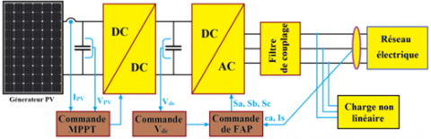
The studied configuration consisting of a PVG connecting to the DC bus of a two-stage three-phase voltage source inverter (2S-VSI). An electrical grid feeds power to a non-linear load consisting of a PD3 rectifier with a resistor in series with an inductor. In this structure, there is also a DC-DC steep-up converter combined to the MPPT control. The synoptic in Figure 2 illustrates this configuration.
Figure 2. Global scheme of GPV-FAP
2.2 Modeling of electronic PVG
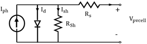
In this paper, a solar cell electronic circuit to emulate the operation of a photovoltaic (PV) cell is presented as shown in Figure 3 [6]. The equation representing the current and voltage relationship of the PV cell is given as follow [6-8]:
Figure 3. Potovoltaic cell (single-diode)
$I_{p v}=I_{p h}-I_{s}\left[\exp \left(\frac{v+I R_{s}}{v_{t} n}\right)-1\right]-\frac{v+I R_{s}}{R_{p}}$ (1)
with
$a=\frac{n \cdot K \cdot T_{\operatorname{sinc}}}{q}=n \cdot v_{t}$ (2)
$v_{t}=\frac{K T_{\text {snc }}}{q}$ (3)
where, $\mathrm{I}_{\mathrm{ph}}$ is the photocurrent $\mathrm{PV}$ module, $\mathrm{I}_{s}$ is the saturation current of the $\mathrm{PV}$ module, $\mathrm{R}_{s}$ represent the serie resistor, $\mathrm{R}_{p}$ represent the parallel resistor. I $_{\mathrm{s}, \mathrm{Smc}}$ the reverse saturation current, $\mathrm{I}_{\mathrm{sc}, \mathrm{smc}}$ the short circuit current per cell, $\mathrm{I}_{\mathrm{s}}$ the saturation current of the $\mathrm{PV}$ cell, $\mathrm{V}_{\mathrm{t}}$ is the thermal voltage of the cell, $\mathrm{n}$ is the diode ideality factor, $\mathrm{k}$ is the Boltzmann's constant $(1.380650310-23 \mathrm{J} / \mathrm{K}), \mathrm{V}$ is the voltage of the diode, q is the charge of an electron $(q=1.610-19 \mathrm{C}), \mathrm{k}_{\mathrm{i}}$ is the current coefficient, $\mathrm{k}_{\mathrm{v}}$ is the Voltage coefficient, $\mathrm{V}_{\mathrm{oc}}$ is the open circuit voltage at the nominal condition.
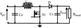
2.3 DC/DC boost converter
A Boost converter [7, 9] is classified according to the mode of the inductor’s operation, as it is the element responsible for raising the current to store it in the capacitor. Thus, it can generate high voltage at the output and deliver it to the load. A model of the equivalent circuit is given by the Figure 4. The relation between the Boost's input and output voltages is as follows:
$\frac{V_{\text {load}}}{V_{p v}}=\frac{1}{1-\alpha}$ (4)
Figure 4. DC-DC boost converter
2.4 MPPT PV control system based Adaline
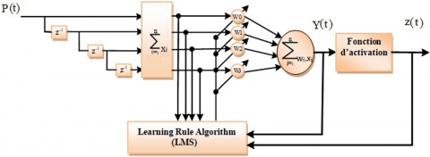
The MPPT control technique proposed is an adaptive neural controller type Adaline for application to a DC-DC step-up (boost) converter. The Adaline is an intelligent control consists of a single neuron with linear activation function like is shown in the Figure 5, whose output is calculated as [10]:
$\mathrm{z}(\mathrm{k})=f(v(\mathrm{k}))$ (5)
with:
$\mathrm{v}(\mathrm{k})=b(\mathrm{k})+\sum_{i=0}^{3} w_{i}(\mathrm{k}) x_{i}(k)$ (6)
$z_{i}=y_{i}=w_{i}^{T} x+w_{i 0} x \in R^{n}, y \in R^{m}, z \in R^{m}$ (7)
The separator planes of the classes have as equation [11]:
$w_{i}^{T} x+w_{i 0}=0 \forall i=1, \ldots, m$ (8)
Supposing that the activation is linear and the input bias is neglected, the formula is as follows:
$z(\mathrm{t})=y(\mathrm{t})=\sum_{i=0}^{3} w_{i}(\mathrm{t}) x_{i}(\mathrm{t})$ (9)
Hence f is the activation function, v(k): activation function, b: value of the bias, xiinput signals, p(t) represents network inputs over time, wi is the synaptic weight vector, z(t) is the neural network output, y(t) is the weighted sum of the inputs and weights before the activation function and k indicates the delay time compared to the first input data. The most common error function is the Man Square Erreur (MSE), by developing the Eq. (7), the network response can be obtained from the first instant of time. Let us take the following input-output torque: p(t), d(t) presented at time t. With $p(t) \epsilon\left[\mathrm{p}_{1}, \mathrm{p}_{2}, \ldots, \mathrm{p}_{\mathrm{q}}\right]$ is the representation of the network inputs. d(t) denotes the output desired vector [11]:
$\mathrm{d}(t)=\left[\mathrm{d}_{1}(\mathrm{t}), \ldots, \mathrm{d}_{m}(\mathrm{t})\right]^{T}$ (10)
Knowing that
$W=\left[\begin{array}{l}\mathrm{W}(0) \\ W(1) \\ W(2) \\ W(3)\end{array}\right] \quad p=\left[\begin{array}{l}\mathrm{p}(\mathrm{t}) \\ \mathrm{p}(\mathrm{t}-1) \\ \mathrm{p}(\mathrm{t}-2) \\ \mathrm{p}(\mathrm{t}-3)\end{array}\right]$, $X=[W], Z=[P], y(1)=X^{T} Z$ (11)
The output of the Adaline is calculated as a function of p(t) at time t giving as follow [11]:
$y_{i}=w_{i}(t)^{T} p(t)+\mathrm{w}_{i 0}(t)=X_{i}^{T}(t) \mathrm{Z}(\mathrm{t})$ (12)
Through the adjustment of the weights Xi the error can be minimized as given by:
$e_{i}(t)=d_{i}(\mathrm{t})-\mathrm{y}_{i}(t)$ (13)
The mathematical expectation of the square of the error that the LMS algorithm consists of minimizing, taken on all the pairs: [Pk, dk] for k=[1, 2, …, q] [11] is:
$E\left(e_{i}^{2}(t)\right)=E\left[\left(d_{i}(\mathrm{t})-\mathrm{y}_{i}(t)\right)^{2}\right]$ (14)
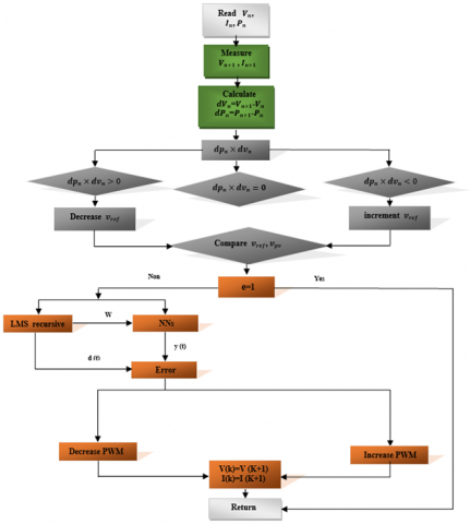
The flowchart given in Figure 6 illustrates a proposed MPPT regulator concept using an Artificial Neural Network (ANN) type Adaline.
Figure 5. Scheme of the Adaline controller
Figure 6. Flowchart of the suggested algorithm based on a combination of Adaline and P&O
The neural-finite set model technique proposed in this part is a Predicted harmonic currents control. This suggested technique is based on the identification of harmonics using adaptive neural controller type Adaline. Predictive current control of the finite set model requires measurements on grid voltages $\mathrm{V}_{\mathrm{s}}$, DC bus voltage $\mathrm{V}_{\mathrm{dc}}$ and nonlinear load currents $\mathrm{il}_{\mathrm{abc}}$. In addition, the DC bus voltage is regulated as a function of the reference power generated by using an Adaline-type neural regulator. The voltage loop of the DC link applies a single PI regulator in order to keep it fixed to a reference value of (200 V). The reference harmonic currents $i f_{a, b, c}^{*}$ are calculation method based on the extraction of the harmonics with the Adaline in the DQ reference frame. Then, a calculation cost function is formulated containing a desired control system after predicting the currents measured by the PAF $i f_{a b c}(k+1)$ for a one-ahead step prediction. These quantities have been expressed in orthogonal coordinates (α, β) of the currents after the Concordia transformation. When the cost function developed in each sampling time has been optimized for the set of seven voltage vectors to which the inverter applies to the load, a voltage vector that minimizes the cost function is applied to the terminals of the PAF. This procedure will be repeated at each (K+1) sampling instant.
3.1 PAF modelisation
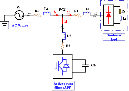
A PAF is a bi-directional current converter connected in parallel with the grid using a passive filter ($\mathrm{L}_{\mathrm{f}}, \mathrm{R}_{\mathrm{f}}$). Figure 7 [12] shows the system under study. The load current ($\mathrm{i}_{1}$) was calculated as the sum of the PAF injection current ($i_{f}$) and the line current ($i_{g}$) for the three phases [11-14]. The voltage equation for each of the three phases can be given as [12, 13]:
$v_{s k}=v_{f k}-v_{L f k}-v_{R f k}$ (15)
$=v_{f k}-L_{f} \frac{d_{i j k}}{d t}-R_{f} i_{f k}$ (16)
with $\mathrm{k}=\mathrm{a}, \mathrm{b}, \mathrm{c}$
Figure 7. Principle scheme of a PAF
For the DC side we have [12, 13]:
$C_{d c} \frac{d V_{d c}}{d t}=S_{a} i_{f a}+S_{b} i_{f b}+S_{c} i_{f c}$ (17)
where, Sabc=(Sa, Sb, Sc) represent three commutation states of the three branches of the inverter. if=(ifa, ifb, ifc) represent the PAF injected current, they are provided by [14]:
lf $\frac{d i f}{d t}=V_{f}-V_{s}-R f . i f$ (18)
Vs=(Vsa, Vsb, Vsc) are the 3- phase grid voltages (without taking into account the passive grid filter) and Vf=(vfa, vfb, vfc)represent the inverter output voltages as given by [14]:
$V_{f}=V_{d c} \cdot H, S_{a b c}$ (19)
Vdc is the voltage of DC bus, H is the switching inverter matrix.
$H=\left[\begin{array}{rrr}\frac{2}{3} & -\frac{1}{3} & -\frac{1}{3} \\ -\frac{1}{3} & \frac{2}{3} & -\frac{1}{3} \\ -\frac{1}{3} & -\frac{1}{3} & \frac{2}{3}\end{array}\right]$ (20)
3.2 Theory of the two-phase method based on the extraction of harmonics with Adaline in the DQ reference
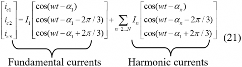
In this work we have proposed to identify the harmonics with the synchronous reference frame (SFR) [15, 16] method combined with Adaline or what is called the two-phase method [17]. Consider the case of the three-phase polluted current equation, written as follows [18]:
From where it can be modelled according to the following relationship [18]:
$\left[\begin{array}{c}i_{c 1} \\ i_{c 2} \\ i_{c 3}\end{array}\right]=T_{32} P(w t)\left[\begin{array}{c}i_{D} \\ i_{Q}\end{array}\right]$ (22)
where, T32: represents the passage matrix in the αβ reference, P(wt): represents the passage matrix in the DQ reference. iD and iQ represents the currents in the DQ reference. The currents in the αβ frame that represent the first transformation part are given by the following equation [18]:
$\left[\begin{array}{c}i_{\alpha} \\ i_{\beta}\end{array}\right]=T_{32}^{T}\left[\begin{array}{c}i_{c 1} \\ i_{c 2} \\ i_{c 3}\end{array}\right]=$$\sum_{n=1 \ldots N} \sqrt{\frac{3}{2} I_{n}}\left[\begin{array}{c}\cos \left(n w t-\alpha_{n}\right) \\ \sin \left(n w t-\alpha_{n}\right)\end{array}\right]$ (23)
Using the park transformation on currents in Eq. (23), we obtain [18]:
$\left[\begin{array}{c}i_{D} \\ i_{Q}\end{array}\right]=P(-w t)\left[\begin{array}{c}i_{\alpha} \\ i_{\beta}\end{array}\right]$$=\sqrt{\frac{3}{2} I_{1}}\left[\begin{array}{l}\cos \left(\alpha_{n}\right) \\ -\sin \left(\alpha_{n}\right)\end{array}\right]+$$\sum_{n=2, \ldots N} \sqrt{\frac{3}{2} I_{n}}\left[\begin{array}{l}\cos \left((n-1) w t-\alpha_{n}\right) \\ \sin \left((n-1) w t-\alpha_{n}\right)\end{array}\right]$ (24)
These biphase currents consist of two terms, a DC and an AC component. We have [18]:
$\left[\begin{array}{l}\overline{i_{D}} \\ \overline{i_{Q}}\end{array}\right]=\sqrt{\frac{3}{2} I_{1}}\left[\begin{array}{l}\cos \alpha_{1} \\ -\sin \alpha_{1}\end{array}\right]$ (25)
and
$\left[\begin{array}{c}\tilde{i}_{D} \\ \tilde{i}_{Q}\end{array}\right]=$$\sum_{n=1 \ldots N} \sqrt{\frac{3}{2} I_{n}}\left[\begin{array}{l}\cos \left((n-1) w t-\alpha_{n}\right) \\ \sin \left((n-1) w t-\alpha_{n}\right)\end{array}\right]$ (26)
The calculated reference harmonic currents are given as follow:
$\left[\begin{array}{c}i_{r e f 1} \\ i_{r e f 2} \\ i_{r e f 3}\end{array}\right]=T_{32} P(w t)\left[\begin{array}{c}\tilde{i}_{D} \\ \tilde{i}_{Q}\end{array}\right]$ (27)
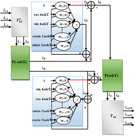
with $\overline{l_{D}}$ and $\overline{l_{Q}}$ are the DC components which constitute the fundamental currents in the reference frame $D Q \cdot \tilde{\imath_{D}}$ and $\tilde{\iota_{Q}}$ are the $\mathrm{AC}$ components which constitute the harmonic currents in in the reference frame $D Q .$ Figure 8 shows the identification structure of the harmonic currents in the $D Q$ reference frame, two Adaline are used instead of a Low Pass Filter (LPF) to extract the harmonic currents. From Eq. (24) the two currents can be written separately as follows [18]:
$i_{D}=\sqrt{\frac{3}{2}} I_{1} \cos \left(\alpha_{1}\right)+\sum_{n=2 \ldots N} \sqrt{\frac{3}{2}} I_{n} \cos \left((n-1) w t-\alpha_{n}\right)$$=\sqrt{\frac{3}{2}} I_{1} \cos \left(\alpha_{1}\right)+\sum_{n=2 \ldots N} \sqrt{\frac{3}{2}} I_{n}\left(\cos (n-1) w t \cos \alpha_{n}+\sin (n-1) w t \sin \alpha_{n}\right)$ (28)
$i_{Q}=-\sqrt{\frac{3}{2}} I_{1} \sin \left(\alpha_{1}\right)+\sum_{n=2 \ldots N} \sqrt{\frac{3}{2}} I_{n} \sin \left((n-1) w t-\alpha_{n}\right)$$=-\sqrt{\frac{3}{2}} I_{1} \sin \left(\alpha_{1}\right)+\sum_{n=2} \sqrt{\frac{3}{2}} I_{n}\left(\sin (n-1) w t \cos \alpha_{n}-\cos (n-1) w t \sin \alpha_{n}\right)$ (29)
with the vector notations, Eqns. (28) and (29) can be written as follows [18]:
$i_{D}=W_{D}^{T} X_{D}(t)$ (30)
$i_{Q}=W_{Q}^{T} X_{Q}(t)$ (31)
with
$W_{D}^{T}=\left[\sqrt{\frac{3}{2}} I_{1} \cos \alpha_{1} \sqrt{\frac{3}{2}} I_{5} \cos \alpha_{5} \ldots \sqrt{\frac{3}{2}} I_{n} \cos \alpha_{n}\right]$ (32)
$X_{D}(t)=[1 \cos 4 w t \ldots \sin (n-1) w t]$ (33)
$W_{Q}^{T}=\left[-\sqrt{\frac{3}{2}} I_{1} \sin \alpha_{1} \sqrt{\frac{3}{2}} I_{5} \cos \alpha_{5} \ldots \sqrt{\frac{3}{2}} I_{n} \sin \alpha_{n}\right]$ (34)
and
$X_{Q}(t)=[1 \sin 4 w t \ldots \cos (n-1) w t]$ (35)
The two vectors XD(t) and XQ(t) represent the inputs of the two Adaline. The two vectors $W_{D}^{T^{-}}$ and $W_{Q}^{T}$ represent the weights of the two Adaline. According to Figure 8 [18] there are two Adaline arrays each with its own weight W0(k), the first one estimates the Direct component of the two-phase current through the D axis, the second one estimates the DC component of diphase current along the Q axis. We can also find the alternating components given by $\tilde{\imath}_{D}$ and $\tilde{\imath}_{Q}$ representing the harmonic currents along the two axes D and Q.
Figure 8. Structure of diphase method based on the extraction of harmonics with Adaline in the DQ reference frame
Figure 9. FS-MPCC principle scheme applied to 2L-VSI
3.3 Predictive current control applied to PAF
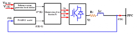
Finite set model predictive current control (FS-MPCC) represents an advanced strategy to control Power Inverters [19]. The model used is based on a mathematical analysis system to predict their future behaviour [19]. Then, a cost function must be defined in order to select an optimized controlling action [19-21]. Figure 9 illustrates a diagrammatic representation of the Predictive Control Strategy applied to the PAF, where [14]: if*(k) represents the reference harmonic current identified by the diphase method based on the extraction of harmonics with Adaline in the DQ reference frame. if(k) represent the m measured values at time k and if(k+1) represent the predicted m-state values corresponding to n switching states possible at time k+1. The error between reference values and predicted values is achieved to minimise the cost function as well as the switching states of the inverter [19, 21].
Subsequently, commutation signals corresponding to the selected switching state, S, will be applied directly to the inverter. In one-step forward prediction k+1, a Euler approach is used to predict the harmonic currents resulting from the discretization of Eq. (18) injected by the PAF using a sampling time Euler approximation. For the implementation in real time, predictions in two steps k+1, k+2 will be used in order to compensate the time delay within the measurement chain. Predicted harmonic currents (also called filtered currents) in the three phases have been given in [14, 22] as follow:
$i f_{a}(\mathrm{k}+1)=\mathrm{T}_{e} \frac{V_{f a}(\mathrm{k})-V_{s a}(\mathrm{k})}{L f}+\left(1-\frac{R_{f} T_{e}}{L f}\right) i f_{a}(\mathrm{k})$
$i f_{b}(\mathrm{k}+1)=\mathrm{T}_{e} \frac{V_{f b}(\mathrm{k})-V_{s b}(\mathrm{k})}{L f}+\left(1-\frac{R_{f} T_{e}}{L f}\right) i f_{b}(\mathrm{k})$
$i f_{c}(\mathrm{k}+1)=\mathrm{T}_{e} \frac{V_{f c}(\mathrm{k})-V_{s c}(\mathrm{k})}{L f}+\left(1-\frac{R_{f} T_{e}}{L f}\right) i f_{c}(\mathrm{k})$ (36)
In order to determine the best of the 7 voltage vectors [19] that should be applied in the next k+1 sampling cycle, the cost function must be reduced to a minimum. In our study for 2-level VSI current control, a simple cost function that minimizes the root MSE between the identified reference harmonic currents and the currents predicted by the PAF is defined in absolute value. Filter currents are considered to be controlled in an actual abc frame given by [14, 22]:
$F_{c}=\left|i f_{a}^{*}(\mathrm{k}+1)-\mathrm{if}_{a}(\mathrm{k}+1)\right|+$$\left|i f_{b}^{*}(\mathrm{k}+1)-\mathrm{if}_{b}(\mathrm{k}+1)\right|+$$\left|i f_{c}^{*}(\mathrm{k}+1)-\mathrm{if}_{c}(\mathrm{k}+1)\right|$ (37)
where, $f_{a}^{*}(k+1), f_{b}^{*}(k+1), f_{c}^{*}(k+1)$ are the reference harmonic currents of phases 'a, b', c' identified based on the extraction of harmonics with Adaline in the DQ reference frame.
with at the instant $(\mathrm{K}+1) f_{a}^{*}(k+1)=i f_{a}^{*}(k)$.
To investigate the feasibility of predictive current control using a finite set model on the PAF [23], the global control scheme given in Figure 10 [24] is implemented on the Matlab/Simulink.
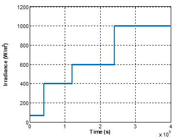
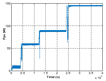
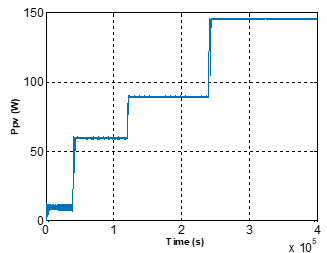
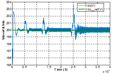
In this part, the system proposed is validated by simulations with the Matlab/Simulink. The PVG is composed of 72 PV modules connected in series based on the FSM 145W-24 PV panel. Optimal parameters applied to the proposed GPV-FAP system are presented in Table 1. Figure 11 presents the irradiation profile at a fixed temperature of 25℃, Figure 12 presents the power extracted from the PVG by the P&O method which shows oscillations around MPP as well as energy losses at each step change of irradiation compared to the Adaline based neural method. This latter gives good results as shown in Figure 13, with no energy loss and no oscillations around MPP. Moreover, the Adaline-based algorithm quickly achieves the expected PPM within a short period of time. Figure 14 and Figure 15 show the $D C$ voltage $\left(V_{d c}\right)$ and its reference $\left(V_{d c-r e f}\right) .$ Figure 14 confirms that the Adaline-based PI neural regulator works very well because the $V_{d c}$ signal follows its reference. It can also be seen that at each change of irradiation the $V_{d c}$ signal try to follow the irradiation profile but it quickly returns to its reference $V_{d c-r e f}$ without energy loss in comparison with Figure 15 which shows a degradation of signal energy quality in function of oscillations with a classical PI regulator based on the P&O control. The DC link voltage dynamic is demonstrated when the filtering step is introduced at a reference voltage value of 200V.
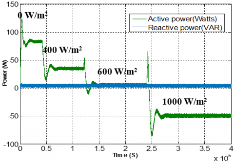
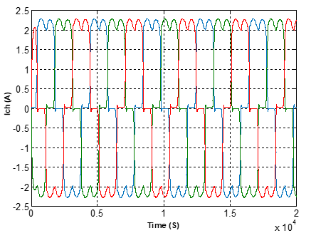
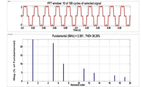
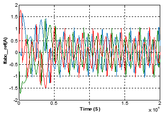
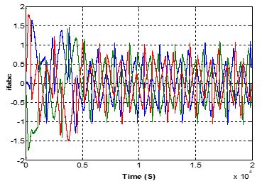
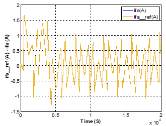
As a result, the DC bus voltage controller with an Adaline-based PI has a good synthesization due to the fact that the voltage followed its reference. Figure 16 shows the active energy injected into the grid through the Adaline-based neural control as well as the compensation of the reactive energy. For a sampling time of 10-4, Figures 17, 18 show the performance of the system under study before filtering and activation of the predictive control. The grid currents before filtering appear highly distorted with no sinusoidal waveform with a high THD of about 26.26%. The non-linear load absorbs non-sinusoidal currents as shown in Figure 17. Like appear, currents from three-phase source are distorted and unsynchronised to respective voltages. The PVG-PAF system allows injecting the solar power from the PVG to the grid, it injects currents into the PCC which are equal to the calculated reference currents $if_{abc_ref}$ (see Figure 19), but in opposite phases as illustrated in Figure 20. Both the injected current and the reference current of the PVG-PAF are monitored with nearly negligeable error such as shown in Figure 21. The improvement reason for highly distorted with no sinusoidal waveform is that the harmonics generated by these no-linear loads circulate in electrical grids and can disturb the normal operation of certain electrical equipment or even cause their destruction. These harmful effects can appear instantaneously or occur with a delay for both the distributor and the users. It is for these reasons that the filtering of current and voltage distortions is suitable solution.
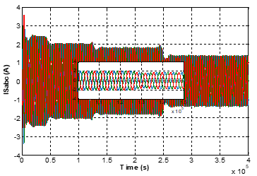
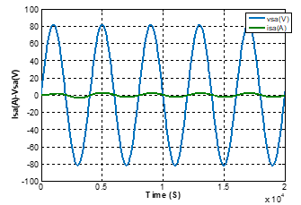
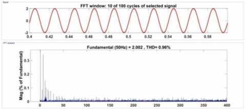
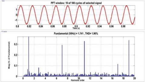
In addition, the filter currents approach their references, which means that FS-MPC represents a strong control technique in this type of application. When PAFs are implemented, grating currents show up in sinusoidal waveform according to the imposed irradiation profile (see Figure 22), as do the sinusoidal waveform source currents imposed by the PVG-PAF, as shown in Figure 23. Figure 24 shows the steady state for the grid voltage and current with perfect synchronization which proves the unity of the power factor with a low THD current (%) of about 0.96% with the Adaline Neuro-Predictive Control (ANPC) as shown in Figure 25, in comparison to PO-Hystérésis Control (PHC) with a THD current (%) of about 1.96% as shown in Figure 26.
Table 1. Parameters of the proposed PVG - PAF
|
Parameter |
Value |
|
Typical peak power $\left(\mathrm{P}_{\mathrm{mpp}}\right)$ |
145W |
|
Voltage et peak power $\left(\mathrm{V}_{\mathrm{mp}}\right)$ |
34.4 V |
|
Current at peak power $\left(\mathrm{I}_{\mathrm{mp}}\right)$ |
4.2A |
|
Short-circuit current $\left(\mathrm{I}_{\mathrm{Sc}}\right)$ |
4. 7A |
|
Open-circuit Voltage $\left(\mathrm{V}_{\mathrm{oc}}\right)$ |
43.5V |
|
Temperature coefficient of Isc ($\infty$) |
0.0065% /°C |
|
Temperature coefficeint of $\operatorname{Voc}(\beta)$ |
-0.36099% /°C |
|
Series cell $\left(\mathrm{N}_{s}\right)$ |
72 |
|
Parallel cell $\left(\mathrm{N}_{p}\right)$ |
1 |
|
Inductor in the boost converter circuit (L) |
0.2H |
|
Capacitor in the boost converter circuit (Ce) |
10 e-6F |
|
Capacitor in the boost converter circuit (Cs) |
1000 e-6F |
|
Power supply voltage Source $V_{s}$ |
220 V |
|
Frequency $f_{s}$ |
50 HZ |
|
Grid line impedance $\left(L_{s}, R_{s}\right)$ |
3.55e-3H, 0.4 $\Omega$ |
|
APF inductor Lf |
15e-3H |
|
DC Capacitor $C_{d c}$ |
1100 e-6 F |
|
DC Voltage $\mathrm{V}_{\mathrm{dc}}$ |
200 V |
|
Nonlinear load resistor side Rl |
$6 \Omega$ |
|
Nonlinear load inductor side Ll |
20 e-3H |
|
Sampling Time $\mathrm{T}_{\mathrm{s}}$ |
5e-06s |
Figure 10. Global scheme of PAF control system based on neural FS-MPC control
Figure 11. Irradiation profile
Figure 12. Maximum power extracted using P&O algorithm
Figure 13. Maximum power extracted using Adaline
Figure 14. DC regulated voltage control using a PI Adaline based neural controller
Figure 15. DC regulated voltage control using a conventional PI regulator
Figure 16. Active power injected into the grid using Adaline MPPT algorithm
Figure 17. Load current
Figure 18. a) Source currents before compensation, b) THD before filtering
Figure 19. Reference current identified by the two-phase method
Figure 20. Compensation current
Figure 21. Reference current and compensation current (phase a)
Figure 22. Current profile after filtering according to irradiation profile
Figure 23. Courant de source après compensation
Figure 24. Power factor correction after compensation
Figure 25. a) Source currents after compensation using Adaline Neural Predictive control (ANPC), b) THD after filtering
Figure 26. a) Source currents after compensation using PO- Hystérésis Control (PHC), b) THD after filtering
Table 2 compare the THD current (%) of the proposed method with recent works.
Table 2. Comparison of THDi in % of recent methods with suggested method
|
Works |
Approach |
THDi% |
|
[25] |
Proposed synergetic |
1.03 |
|
[26] |
R-load with Grid+SAPF |
2.48 |
|
[27] |
Modified SRF theory-based control |
3.7 |
|
[28] |
Hysteresis Current Controller (HCC) |
1.74 |
|
[29] |
DPC proposed controlrol |
1.33 |
|
The proposed work |
Proposed Neuronal- Finite Set Mode Predictive Current Control (FS-MPCC) |
0.96 |
This work involves a multifunctional grid-interconnected PV system using a three-phase PAF to improve the quality of electrical energy. Thanks to the PVG-PAF system, the electricity produced by the PVG is injected into the grid. Then, the transmitted power is processed by eliminating harmonic currents and compensating reactive power to correct the power factor. Indeed, the control system developed seeks three objectives: (i) transmit extracted active power from the PVG to the AC grid; (ii) filter the load current harmonic and reactive power components; (iii) regulate the DC bus voltages.
In this work, the theory of the two-phase method based on the extraction of harmonics with Adaline is proposed, as well as, a predictive current control is suggested to control the PAF with 2L-VSI associated to a non-linear load. A MPPT using ADALINE is applied to a DC/DC step-up converter to extract the maximum power of PVG. The feasibility of the proposed system is confirmed by simulation using Matlab/Simulink. An evaluation study with a global MPPT P&O algorithm using a classical hysterisis control inverter is compared to the Adaline Neuro-Prédictive (ANP) control in a constant non-linear load and sudden variable irradiation profile. As a result, the proposed control proves its robustness with a THD of 0.96% for the Adaline Neuro-Prédictive (ANP) control against the classical one with a THD of 1.64% for PO-SFR-Hystérésis (PSH) control as specified by the IEEE 519-1922 norm.
As conclusion, these results affirm the robustness of the proposed PVG-PAF using ANP control strategy.
We would like to thank the Pierre-et-Jeanne Spiegel association for the financial support.
[1] Azzam-Jai, A., Ouassaid, M. (2018). A Multifunctional PV-based shunt active power filter using neural network controller. In 2018 International Symposium on Advanced Electrical and Communication Technologies (ISAECT), Rabat, Morocco, pp. 1-6. https://doi.org/10.1109/ISAECT.2018.8618848
[2] Jauhari, M., Riawan, D.C., Ashari, M. (2018). Control design for shunt active power filter based on p-q theory in photovoltaic grid-connected system. International Journal of Power Electronics and Drive Systems, 9(3): 1064-1071. https://doi.org/10.11591/ijpeds.v9.i3.pp1064-1071
[3] Serghine, H., Merahi, R., Chenni, R., BUŁA, D. (2019). Combined operation of photovoltaic and active power filter system connected to nonlinear load. Revue Roumaine Des Sciences Techniques-Serie Electrotechnique et Energetique, 64(4): 371-376.
[4] Hota, A., Bhuyan, S.K., Hota, P.K. (2020). Modeling & simulation of photovoltaic system connected to grid using Matlab. In 2020 International Conference on Renewable Energy Integration into Smart Grids: A Multidisciplinary Approach to Technology Modelling and Simulation (ICREISG), Bhubaneswar, India, pp. 16-21. https://doi.org/10.1109/ICREISG49226.2020.9174192
[5] Ouchen, S. (2017). Contribution a la commande directe de puissance dediee au filtrage actif, associe a une source photovoltaïque. Doctoral dissertation, Université Mohamed Khider-Biskra. https://doi.org/10.13140/RG.2.2.26158.00329
[6] Chtouki, I., Zazi, M., Feddi, M., Rayyam, M. (2016). LCL filter with passive damping for PV system connected to the network. In 2016 International Renewable and Sustainable Energy Conference (IRSEC), Marrakech, pp. 692-697. https://doi.org/10.1109/IRSEC.2016.7984020
[7] Ihssane, C., Patrice, W., Sami, M. (2019). Design, implementation and comparison of several neural perturb and observe MPPT methods for photovoltaic systems. International Journal of Renewable Energy Research (IJRER), 9(2): 757-770.
[8] Naick, B.K., Chatterjee, K., Chatterjee, T.K. (2018). Assessment of MPPT techniques during the faulty conditions of PV system. Advances in Electrical and Electronic Engineering, 16(1): 15-24. https://doi.org/10.15598/aeee.v16i1.2581
[9] Özgür, C., Teke, A. (2017). A hybrid MPPT method for grid connected photovoltaic systems under rapidly changing atmospheric and Technology. Electric Power Systems Research, 152: 194-210 https://doi.org/10.1016/j.epsr.2017.07.011
[10] Kaminski, M., Orlowska-Kowalska, T. (2012). FPGA implementation of ADALINE-based speed controller in a two-mass system. IEEE Transactions on Industrial Informatics, 9(3): 1301-1311. https://doi.org/10.1109/TII.2012.222645
[11] Borne, P., Benrejeb, M., Haggège, J. (2007). Les réseaux de neurones: présentation et applications. OPHRYS.
[12] Kmail, M. (2012). Investigation of shunt active power filter for power quality improvment. Thesis, Near East University.
[13] Ghadbane, I. (2011). Commande d’un filtre actif triphasé parallele par differents régulateurs. Doctoral dissertation, Faculté des sciences et de la technologie UMKBiskra.
[14] Cherif, A.Y., Hicham, L., Kamel, B. (2018). Implementation of finite set model predictive current control for shunt active filter. In 2018 9th International Renewable Energy Congress (IREC), Hammamet, pp. 1-6. https://doi.org/10.1109/IREC.2018.8362482
[15] Belaidi, R., Haddouche, A. (2017). A multi-function grid-connected PV system based on fuzzy logic controller for power quality improvement. Przegląd Elektrotechniczny, 93: 118-122. https://doi.org/10.15199/48.2017.10.28
[16] Echchaachouai, A., El Hani, S., Hammouch, A., Aboudrar, I. (2017). A two-level sensorless MPPT strategy using SRF-PLL on a PMSG wind energy conversion system. Power Engineering and Electrical Engineering, 15(3): 383-390. https://doi.org/10.15598/aeee.v15i3.2193
[17] Serra, F.M., Giraldo, O.D.M., De Angelo, C.H., Forchetti, D.G. (2019). On the Use of the PQ theory for harmonic current cancellation with shunt active filters. Power Engineering and Electrical Engineering, 17(3): 262-269. https://doi.org/10.15598/aeee.v17i3.3415
[18] Abdeslam, D.O. (2005). Techniques neuromimétiques pour la commande dans les systèmes électriques: application au filtrage actif parallèle dans les réseaux électriques basse tension (Doctoral dissertation).
[19] Feloups, C.E.S., Mohamed, E.E.M. (2019). A novel reduced components model predictive controlled multilevel inverter for grid-tied applications. Advances in Electrical and Electronic Engineering, 17(3): 251-261. https://doi.org/10.15598/aeee.v17i3.3353
[20] Bounab, T. (2016). Commande Prédictive d’un Filtre Actif Parallèle.
[21] Khan, H.S., Aamir, M., Ali, M., Waqar, A., Ali, S.U., Imtiaz, J. (2019). Finite control set model predictive control for parallel connected online ups system under unbalanced and nonlinear loads. Energies, 12(4): 581 https://doi.org/10.3390/en12040581
[22] Meddour, S., Rahem, D., Cherif, A.Y., Hachelfi, W., Hichem, L. (2019). A novel approach for PV system based on metaheuristic algorithm connected to the grid using FS-MPC controller. Energy Procedia, 162: 57-66. https://doi.org/10.1016/j.egypro.2019.04.007
[23] Boussaid, A., Nemmour, A.L., Louze, L., Khezzar, A. (2015). A novel strategy for shunt active filter control. Electric Power Systems Research, 123: 154-163. https://doi.org/10.1016/j.epsr.2015.02.008
[24] Sahli, A., Krim, F., Laib, A., Talbi, B. (2020). Model predictive control for single phase active power filter using modified packed U-cell (MPUC5) converter. Electric Power Systems Research, 180: 106139. https://doi.org/10.1016/j.epsr.2019.106139
[25] Pesdjock, M.J.P., Pone, J.R.M., Kenne, G., Sonfack, L.L. (2020). Contribution of synergetic control to the minimization of harmonics currents injected for grid connected photovoltaic systems. SN Applied Sciences, 2(8): 1-8. https://doi.org/10.1007/s42452-020-3118-0
[26] Rao, B.N., Krishna, P., Yarlagadda, V. (2020). Mitigation of photovoltaic solar system harmonics using shunt active power filter. In 2020 Fourth International Conference on Computing Methodologies and Communication (ICCMC), Erode, India, pp. 566-571. https://doi.org/10.1109/ICCMC48092.2020.ICCMC-000105
[27] Chacko, F.M., George, G.A., Jayan, M.V., Prince, A. (2020). Improved multifunctional controller for power quality enhancement in grid integrated solar photovoltaic systems. World Journal of Engineering. https://doi.org/10.1108/WJE-12-2019-0356
[28] Smadi, A.A., Lei, H., Johnson, B.K. (2019). Distribution system harmonic mitigation using a PV system with hybrid active filter features. In 2019 North American Power Symposium (NAPS), Wichita, KS, USA, pp. 1-6. https://doi.org/10.1109/NAPS46351.2019.9000238
[29] Chelli, Z., Lakehal, A., Khoualdia, T., Djeghader, Y. (2019). Study on shunt active power filter control strategies of three-phase grid-connected photovoltaic systems. Periodica Polytechnica Electrical Engineering and Computer Science, 63(3): 213-226. https://doi.org/10.3311/PPee.14025