Yanghua Gao* | Hailiang Lu
© 2020 IIETA. This article is published by IIETA and is licensed under the CC BY 4.0 license (http://creativecommons.org/licenses/by/4.0/).
OPEN ACCESS
A new compact wideband Coplanar Waveguide (CPW)-fed balanced printed dipole antenna combining multiple symmetric loops and One novel balun DC ground structure, is presented here. This antenna is capable of generating several resonant modes to cover a wide frequency band including CDMA/GSM1800/1900/Wifi/Bluetooth bands. Experimental results demonstrate that the proposed CPW-fed dipole antenna can operate at a wide frequency band from 1710 MHz to 2700 MHz in which the return loss is better than 14 dB. The proposed antenna has a high gain ranging from 2.5 to 3.0 dBi. The proposed antenna utilizes a simple planar compact structure and occupies a small area of only 70.5×30.5 mm2. Details of the antenna design and experimental results are presented and discussed. Therefore, the proposed antenna is very suitable to various applications for high-performance receiving and transmitting.
loaded antenna, resistively loaded, indoor antenna, ultra-wideband (UWB)
Modern communication systems often require to support different communication standards in one setting. Typical features of such communication devices are from mobile-phone functionality and mobile data transmission supported by UMTS network standards, to Global Positioning System capabilities. Other examples are some local wireless network support in the Industrial-Scientific-Medical (ISM) band such as the WiFi or Bluetooth standards at 2.4/5.8 GHz. To guarantee an appropriate working condition for all standards special attention is needed when designing an antenna element for such a communication system [1]. The ability to cover multiple bands while minimizing the structure of slot antennas is still a challenge for antenna designers. Furthermore, the planar inverted-F antenna (PIFA) typically exhibits performance limitations related to the radiating branches, not only generating the lower resonant modes but also exciting several higher order modes. These unexpected higher modes will complicate frequency tuning of the multiband antenna. Additionally, these unexpected higher order modes will affect the power amplifier or low-noise amplifier’s performances and in turn degrade multiband antenna’s radiation properties.
In modern handset communications, antennas like monopole antennas and planar inverted-F antennas, some gain degradation has been often observed when the user holds the handsets at a talk position. This is caused by the current variation on the conducting materials in the handset owing to the human body effect. These applications require therefore a common radiating element that is possibly selective yet flexible enough to adjust the working conditions to the required applications. A possible solution to cover all wanted frequency bands is to use a broadband antenna [2]. Even better is to selectively design the resonating frequencies of the broadband radiating element so to meet the required conditions for operation. The multiband antennas are therefore the optimal solution, promoting the transmission and reception of signals within the bands of interest and damping interferences and signals present in other frequency ranges. In [3], one balance-fed antenna, such undesirable current variation can be reduced remarkably. A folded loop antenna is introduced as a balance feed antenna and the performance analysed. The antenna is formed by two-wire transmission lines which are shorted at the point to be a quarter wavelength from the feed point, and provide infinite impedance. The antenna forms a folded half-wavelength dipole antenna equivalently, and has a one-wavelength structure so that no unbalanced current may be produced on the feed line [4]. By using the self-balanced structure, the current on the surface can be reduced even though an antenna is fed by an unbalanced line. A folded loop antenna has generally narrowband characteristics that equal for both unbalanced and balanced feed cases. By enlarging the strip width ratio, the bandwidth is enlarged up to 45% for balanced feed. However, the same wideband characteristics do not appear for unbalanced feed [5]. A wideband folded loop antenna, with a self-balanced effect, is explained next. The latest trends in the cellular phone and portable handy phone system are to reduce the size and the weight [6]. Antennas used for such handsets must also follow downsizing of the handset unit and wideband characteristics while the antenna performance is unchanged or even improved. Furthermore, built-in antennas are becoming a main requirement for handset antennas. From these viewpoints, in order to broaden bandwidth, a folded loop antenna is modified. A wideband folded antenna is expected to maintain a self-balanced effect even though the bandwidth characteristics are enlarged.
In modern base station communication, one dipole antenna element need be designed to have characteristics like wideband, stable electronic pattern performance and omni direction [7-10]. Some broadband antennas have been designed to operate at the ultra wideband and the Wireless Local Area Networks (WLAN) centered at 2.4 GHz or 5.8 GHz [11-14]. Planar antennas can use either microstrip-line fed [15-18] or co-planar waveguide (CPW)-fed [19-29]. The CPW-fed has many impressive features such as no need of soldering point, easy fabrication and a simple configuration with the single metallic layer. CPW-fed antennas offer satisfactory impedance matching over a wide frequency range while maintaining omni-directional radiation characteristics. As the antenna size decreases, the radiation resistance decreases whereas the quality factor increases, resulting in low efficiency and narrow bandwidth. Hence, how to reduce the antenna size yet maintain the antenna electronic performance is one of the major challenges in the antenna design area.
In this paper, we propose a CPW-fed wideband balanced printed dipole antenna with multiple symmetric loops for base station or handset from 1710 MHz to 2700 MHz. Firstly, we investigate to optimize the antenna structure using the CPW-fed mechanism to generate the maximum bandwidth. Due to the use of the straight feed gap for a CPW-fed dipole antenna, an additional resonant mode adjacent to the antenna’s fundamental resonant mode (0.5-wavelength) can be achieved. These resonant modes of the proposed antenna are established the broadband characteristics. One novel DC ground structure is introduced in this dipole antenna for generating more resonant modes. Because of each loop corresponds to a specific frequency response, multiple loops can generate the multiple frequency response. All frequency responses of multiple loops are coupled together to extend the wide operating frequency range.
In Section II, extensive parametric studies are implemented to optimize the antenna impedance bandwidth and the geometry of proposed CPW-fed antenna. In Section III, the proposed CPW-fed antenna is fabricated to perform the measurements of S-parameter, radiation pattern, and gain for validation. Simulated and measured results are compared in Section III. Finally, Section VI concludes the design of the proposed antenna.
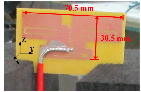
The structure of the proposed DC-ground CPW-fed balanced dipole antenna, which consists of the symmetric loop dipole structure and one novel balun DC ground design, is shown in Figure 1. The proposed CPW-fed dipole antenna is composed of the symmetric dipoles with a rectangular shape of 70.5mm*30.5mm radiation area which is printed on the 1.6 mm FR4 dielectric substrate. The printed-circuit board (PCB) antennas are another type of commonly used antennas due to their good stability, low-cost and easy integration. This FR4 board is with a dielectric constant of 4.4 and a loss tangent of 0.018. The radiating part of the proposed CPW-fed dipole antenna is printed on at the same layer of the FR4 substrate. The symmetric structures have a CPW-fed feeding structure and one novel balun structure symmetrically disposed in the middle of the board. The symmetric dipoles have multiple symmetric loops structure which are composed of the radiated strip lines.
The dimensions as shown in Figure 1 depicts the preferred design parameters. With the antenna length of 70.5 mm, the dipole antenna can generate a fundamental resonant mode (0.5-wavelength) centered at about 1800MHz, admitting the dipole antenna to cover the frequency up to 2700MHz. To extend the frequency up to 2700MHz, there is a need of an additional resonant mode that is activated by a straight feed gap. As shown in the Figure 1., multiple loops are introduced in the proposed antenna where resonant frequencies of multiple loops are coupled to extend the impedance matching in the whole band.
The CPW-fed dipole structure is connected to the feed port through the feeding cable. The multi-resonance mode property of the structure is determined by the generalized transmission line theory. The radiating portion of the presented antenna as symmetric loop dipole structure enables substantial control of different resonance modes by adjusting the impedances and electrical lengths of the symmetric loop dipole elements.
(a) Detailed dimensions of radiating element
(b) Photo of the antenna prototype
Figure 1. Configuration of the proposed balanced antenna on a 1.6-mm FR-4 substrate
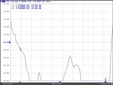
Figure 2. Measured return loss for the proposed antenna
Figure 2 plots the measured S11 of the proposed slot antenna with the dimensions given in Figure 1. The S11 parameters was measured in an anechoic chamber with Agilent Network Analyzer E5063A. The wide band width with a measured <1.5:1 VSWR (-14 dB return loss) bandwidth of 990 MHz (1710~2700 MHz) is obtained, which covers the GSM1800/1900/Wifi operation.
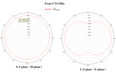
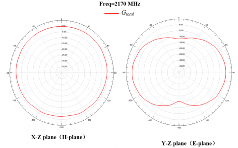
The measured radiation patterns of the fabricated prototype in the anechoic chamber with far-field system at 1710, 2170, and 2450 MHz are shown in Figure 3. The dipole-like radiation patterns are achieved, and the radiation patterns for frequencies over the whole wide band (1710~2700 MHz) are also about the same as those plotted here. This pattern characteristic is similar to those observed for the traditional dipole-like antenna.
(a)
(b)
(c)
Figure 3. Measured radiation patterns at (a) 1710 MHz; (b) 2170 MHz; (c) 2450 MHz.
(a)
(b)
(c)
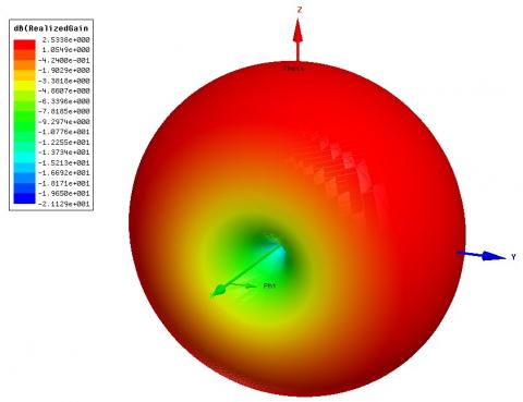
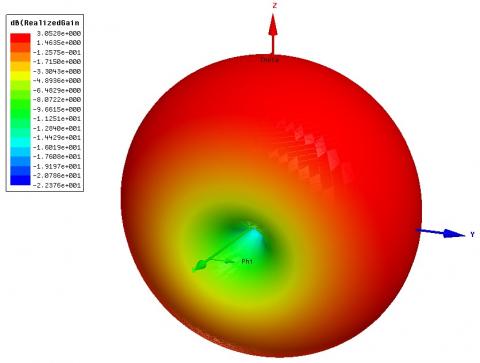
Figure 4. Simulated 3D radiation patterns at a) 1710 MHz; (b) 2170 MHz; (c) 2450 MHz
(a) 1710 MHz
(b) 2170 MHz
(c) 2450 MHz
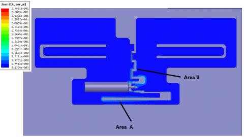
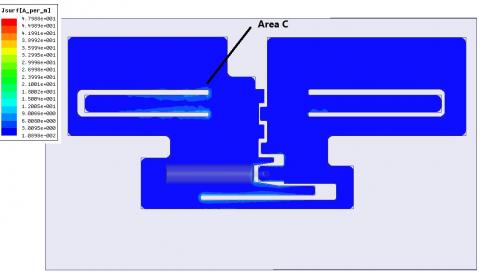
Figure 5. Simulated current distributions
The measured peak gain and radiation efficiency of the proposed antenna are good for practical applications. For the whole band, the antenna gain varies from 2.5 to 3.0 dBi, and the antenna radiation efficiency is larger than about 85% cover the whole wide band. The simulated 3D radiation patterns of the fabricated prototype at 1710, 2170, and are shown and Figure 4 using the Ansoft simulation software HFSS. A typical 3D dipole-like pattern is achieved in this Figure 4.
An important issue to be examined for the proposed antenna using a CPW-fed mechanism is the relationship between the straight feed gap and the matching performance in the desired bandwidth. To demonstrate the resonant modes, the simulated surface current distributions of the proposed antenna at 1710, 2170, and 2450 MHz are shown in Figure 5. The simulated current distributions are obtained using the Ansoft simulation software HFSS. At 1710 MHz, the surface currents flowing around areas A and B are aroused at the direction antenna excited at the fundamental resonant mode (half wavelength). The excited surface currents of areas C at 2170 MHz around with the straight feed gap go right and left in regions close to the gap, respectively. This phenomenon is similar to the conventional dipole antenna excited at the second resonant mode. In the meantime, multiple loops with a topology similar to concentric circles are introduced in the proposed design. Each loop has a different length that generates a separately resonant frequency. The resonant frequencies from these multiple loops are interacted and coupled to generate a wideband effect. Therefore, the proposed antenna is very suitable to various applications for high-performance receiving and transmitting.
As shown in this paper a new DC-ground CPW-fed balanced dipole antenna formed the symmetric loop dipole structure and one novel balun DC ground design is introduced. The prototype of the proposed antenna has been successfully designed and fabricated. The proposed design has the planar structure of small area of only 70.5´30.5 mm2. This antenna can generate multiple resonant modes to cover CDMA/GSM1800/1900/ Wifi/Bluetooth bands. The proposed DC-ground CPW-fed dipole antenna has symmetric radiation structure and a DC ground balun feeding structure. The proposed antenna can have high radiation efficiency and maintain their ultra wideband performance.
[1] Wong, K.L. (2003). Planar antennas for wireless communications. Microwave Journal, 46(10): 144-145.
[2] Morishita, H., Furuuchi, H., Fujimoto, K. (2002). Performance of balance-fed antenna system for handsets in the vicinity of a human head or hand. IEE Proceedings-Microwaves, Antennas and Propagation, 149(2): 85-91. https://doi.org/10.1049/ip-map:20020206
[3] Sewiolo, B., Vinci, G., Fischer, G., Weigel, R. (2009). Mixed-mode S-parameter design of ultra-wideband coupled-line baluns. In 2009 International Conference on Electromagnetics in Advanced Applications, pp. 55-58. https://doi.org/10.1109/iceaa.2009.5297626
[4] Hayashida, S., Morishita, H., Fujimoto, K. (2006). Self-balanced wideband folded loop antenna. IEE Proceedings-Microwaves, Antennas and Propagation, 153(1): 7-12. https://doi.org/10.1049/ip-map:20045152
[5] Skrivervik, A.K., Zurcher, J.F., Staub, O., Mosig, J.R. (2001). PCS antenna design: The challenge of miniaturization. IEEE Antennas and Propagation Magazine, 43(4): 12-27. https://doi.org/10.1109/74.951556
[6] Jing, X., Du, Z., Gong, K. (2006). A compact multiband planar antenna for mobile handsets. IEEE Antennas and Wireless Propagation Letters, 5: 343-345. https://doi.org/10.1109/74.951556
[7] Tsai, C.Y., Chen, O.T.C. (2011). CPW-fed wideband printed planar dipole antenna for digital TV. In 2011 IEEE International Symposium on Antennas and Propagation (APSURSI), pp. 1-4. https://doi.org/10.1109/aps.2010.5561721
[8] Liu, H.W., Ku, C.H., Yang, C.F. (2010). Novel CPW-fed planar monopole antenna for WiMAX/WLAN applications. IEEE Antennas and Wireless Propagation Letters, 9: 240-243. https://doi.org/10.1109/lawp.2010.2044860
[9] Jeon, S., Ryu, K., Lee, Y., Choi, J. (2007). Internal broadband folded monopole antenna for DTV laptop application. In 2007 Korea-Japan Microwave Conference, pp. 81-84. https://doi.org/10.1109/kjmw.2007.4402245
[10] Liu, W.C., Wu, C.M., Chu, N.C. (2010). A compact CPW-fed slotted patch antenna for dual-band operation. IEEE Antennas and Wireless Propagation Letters, 9: 110-113. https://doi.org/10.1109/lawp.2010.2044135
[11] Hsu, C.K., Chung, S.J. (2010). A wideband DVB forked shape monopole antenna with coupling effect for USB dongle application. IEEE Transactions on Antennas and Propagation, 58(9): 3029-3036. https://doi.org/10.1109/tap.2010.2052545
[12] Park, C.H., Rhyu, H., Kim, S.H., Jung, C., Lee, B. (2008). Internal DTV antenna on multilayered ferrite substrate for mobile phone applications. In 2008 IEEE Antennas and Propagation Society International Symposium, pp. 1-4. https://doi.org/10.1109/aps.2008.4619463
[13] Véronneau, S., Roy, J. (2009). RFID benefits, costs, and possibilities: The economical analysis of RFID deployment in a cruise corporation global service supply chain. International Journal of Production Economics, 122(2): 692-702. https://doi.org/10.1016/j.ijpe.2009.06.038
[14] Zou, Z., Chen, Q., Uysal, I., Zheng, L. (2014). Radio frequency identification enabled wireless sensing for intelligent food logistics. Philosophical Transactions of the Royal Society A: Mathematical, Physical and Engineering Sciences, 372(2017): 20130313. https://doi.org/10.1098/rsta.2013.0313
[15] Ko, D., Kwak, Y., Song, S. (2014). Real time traceability and monitoring system for agricultural products based on wireless sensor network. International Journal of Distributed Sensor Networks, 10(6): 832510. https://doi.org/10.1155/2014/832510
[16] Chen, S.Y., Chen, Y.C., Hsu, P. (2008). CPW-fed aperture-coupled slot dipole antenna for tri-band operation. IEEE Antennas and Wireless Propagation Letters, 7: 535-537. https://doi.org/10.1109/lawp.2008.2006071
[17] Regattieri, A., Santarelli, G., Gamberi, M., Gamberini, R. (2014). The use of radio frequency identification technology in packaging systems: experimental research on traceability. Packaging Technology and Science, 27(8): 591-608. https://doi.org/10.1002/pts.2052
[18] Griffin, J.D., Durgin, G.D., Haldi, A., Kippelen, B. (2006). RF tag antenna performance on various materials using radio link budgets. IEEE Antennas and Wireless Propagation Letters, 5: 247-250. https://doi.org/10.1109/lawp.2006.874072
[19] Razavi, S.N., Haas, C.T. (2011). Using reference RFID tags for calibrating the estimated locations of construction materials. Automation in Construction, 20(6): 677-685. https://doi.org/10.1016/j.autcon.2010.12.009
[20] Bourqui, J., Okoniewski, M., Fear, E.C. (2007). Balanced antipodal Vivaldi antenna for breast cancer detection. https://doi.org/10.1049/ic.2007.1262
[21] Chen, H.D. (2008). Compact broadband microstrip-line-fed sleeve monopole antenna for DTV application and ground plane effect. IEEE Antennas and Wireless Propagation Letters, 7: 497-500. https://doi.org/10.1109/lawp.2008.2004213
[22] Chae, S., Yoshida, T. (2010). Application of RFID technology to prevention of collision accident with heavy equipment. Automation in Construction, 19(3): 368-374. https://doi.org/10.1016/j.autcon.2009.12.008
[23] Geng, J., Jin, R., Wang, W., He, W., Ding, M., Wu, Q., Fang, Z. (2007). A new quasi-omnidirectional vertical polarisation antenna with low profile and high gain for DTV on vehicle. IET Microwaves, Antennas & Propagation, 1(4): 918-924. https://doi.org/10.1049/iet-map:20060264
[24] Yuan, B., Cao, Y., Wang, G. (2011). A miniaturized printed slot antenna for six-band operation of mobile handsets. IEEE Antennas and Wireless Propagation Letters, 10: 854-857. https://doi.org/10.1109/lawp.2011.2165313
[25] Chen, S.W., Wang, D.Y., Tu, W.H. (2013). Dual-band/tri-band/broadband CPW-fed stepped-impedance slot dipole antennas. IEEE Transactions on Antennas and Propagation, 62(1): 485-490. https://doi.org/10.1109/tap.2013.2287523
[26] Cao, Y., Yuan, B., Wang, G. (2011). A compact multiband open-ended slot antenna for mobile handsets. IEEE Antennas and Wireless Propagation Letters, 10: 911-914. https://doi.org/10.1109/lawp.2011.2166990
[27] Ban, Y.L., Qiang, Y.F., Chen, Z., Kang, K., Guo, J.H. (2014). A dual-loop antenna design for hepta-band WWAN/LTE metal-rimmed smartphone applications. IEEE Transactions on Antennas and Propagation, 63(1): 48-58. https://doi.org/10.1109/TAP.2014.2368573
[28] Wu, D., Cheung, S.W., Yuk, T.I. (2015). A compact and low-profile loop antenna with multiband operation for ultra-thin smartphones. IEEE Transactions on Antennas and Propagation, 63(6): 2745-2750. https://doi.org/10.1109/TAP.2015.2412962
[29] Zaharis, Z.D., Skeberis, C., Xenos, T.D., Lazaridis, P.I., Cosmas, J. (2013). Design of a novel antenna array beamformer using neural networks trained by modified adaptive dispersion invasive weed optimization based data. IEEE Transactions on Broadcasting, 59(3): 455-460. https://doi.org/10.1109/tbc.2013.2244793