Abdelkadir Belhadj Djilali* | Adil Yahdou | Elhadj Bounadja | Fayçal Mehedi
© 2020 IIETA. This article is published by IIETA and is licensed under the CC BY 4.0 license (http://creativecommons.org/licenses/by/4.0/).
OPEN ACCESS
The variable step size incremental conductance method (VSS-INC) is a very effective method. However, the VSS-INC method suffers from drifting during a rapid change of irradiation. Drifting is caused by the wrong decision made by the conventional VSS-INC method of the first step size perturbation delivered to varying the duty cycle at a rapid change in irradiation. Modified VSS-INC method has been proposed to stopping the drift problem by incorporating necessary information about the decision-making process during a rapid change of irradiation. The information used is the change in current, change in voltage and the derivative of the irradiation function. Drift problem is clearly shown in this paper for the conventional VSS-INC method. The Boost converter used to verify the efficacy of the modified VSS-INC method. The proposed method demonstrated a high efficacy in stopping the drift problem in the tracking of MPP at the rapid change of irradiation.
photovoltaic panel, boost converter, variable step size incremental conductance method
In the recent period, the increasing demand for energy has grown tremendously. The improvement of living standards is expected to lead increased pressure on energy supplies.
Increased fossil fuel prices have prompted many countries to use new energy sources as renewable energies. Renewable energy is produced of through resources that naturally renew themselves in short periods of time of through natural processes [1].
Photovoltaic (PV) system is a solution to a lot of problems such as energy security and reducing toxic gas emissions. It contributes significantly to creating jobs and reducing poverty and the costs of consuming electric energy [2-4].
Therefore, this source has become the subject of research for energy extraction with very high reliability and lower cost. In recent years, many maximum power point tracking (MPPT) strategies has been proposed with differences in complexity, convergence speed and efficiency in extracting the maximum point [5-9].
The INC algorithm is the most used algorithms to track the maximum point of PV systems. Conventional INC algorithms can be categorized into fixed step size (FSS) and variable step size (VSS).
The variable step size Incremental Conductance MPPT method (VSS-INC) introduced as the changing rules of step sizes. The larger step size would be used if the power point is away from the maximum power point to accelerate the tracking speed. Accordingly, the smaller tracking step size would be adapted in order to precision. If the power point is near the MPP in this case the variable step size Incremental Conductance (VSS-INC) method it cannot satisfy the requirements of MPPT in rapid change of irradiation. A lot of variable step size Incremental Conductance method has been proposed [10-13], in which the step size is automatically adjusted by the derivative of power with respect to current (dP/dI), to voltage (dP/dV) or to duty cycle (dP/dD). The difference between the variable step size Incremental Conductance (VSS-INC) method and the others incremental conductance is the step size calculation, a constant value N is often multiplied with the derivative (dP/dI, dP/dV, dP/dD). These conventional methods of VSS-INC have focused on treating oscillation around of the maximum power point (MPP) but it did not address the problem of drifting when the irradiation changes rapidly.
The rapid change in irradiation causes the variable step size Incremental Conductance method has a drift problem in the tracking of the maximum power point MPP.
This paper provides an accurate solution to the problem of drifting by adding some adjustments in the conventional VSS-INC method. This addition consists of two sides, one of which stopping the drift problem when the irradiation increases rapidly and the other when the rapid decrease of irradiation. Each side contains two parameters, the change in current (dI) and the change in voltage (dV). The two sides are activated by the condition abs(dλ /dt) that captures the rapid changes of irradiation and this allows the modified VSS-INC method to give the correct decisions on the first step size perturbation (small) instead of large during the rapid change of irradiation.
In order to verify the proposed VSS-INC method, a boost is designed to adjust the equivalent resistance of the photovoltaic panel, which is a very important to the maximum power point tracking operation.
This paper is prepared as follows: In Section 2, the photovoltaic (PV) system is presented.
Section 3 analyzes the drift problem in the tracking of maximum power point. Section 4 explained the proposed modified VSS-INC method and in section 5 the simulation results are presented and discussed. Section 6 gives the conclusion of the paper.
As shown in Figure 1, the PV system consists of three important blocks: the photovoltaic panel, the MPPT controller and the Boost converter.
Figure 1. Photovoltaic (PV) system
2.1 Model and characteristics of PV panel
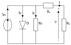
A solar cell is a semiconductor device that converts sunlight energy directly into electricity. Figure 2 shows the equivalent circuit for this cell.
Figure 2. Single-diode equivalent circuit
The Current-Voltage characteristic of a photovoltaic cell is given by the following equation [10]:
$I=I_{p h}-I_{s}\left[e^{\left(\frac{q}{A K T}\left(V+I R_{s}\right)\right)}-1\right]-\frac{V+I R_{s}}{R_{p}}$ (1)
where:
$I_{s}=I_{S R E F}\left(\frac{T}{T_{r e f}}\right)^{3} e^{\left[\frac{q E_{g}}{A K}\left(\frac{1}{T_{r e f}}-\frac{1}{T}\right)\right]}$ (2)
$3- If \frac{d I}{d V}<-\frac{I}{V} power point is in the right of MPP$ (3)
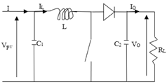
2.2 Boost converter
The boost converter is widely used in photovoltaic systems due to its efficiency compared with other.
Boost converter is a linear system adaptation between the PV and the load in which the output voltage is higher to the input voltage which generated by the PV panel [12, 14].
The boost converter type is shown in Figure 3.
Figure 3. Boost
The mathematical model of the Boost is:
$\left\{\begin{array}{l}I=I_{L}+C_{1} \frac{d V}{d t} \\ V=L \frac{d I_{L}}{d t}+V_{0}(1-D) \\ (1-D) I_{L}=C_{2} \frac{d V_{0}}{d t}+I_{0}\end{array}\right.$ (4)
where, IL and V0 are the inductor current and output capacitor voltage, respectively, D is the duty cycle.
2.3 Conventional fixed step size INC MPPT method
This method relied heavily on the conventional P&O method, it based on the derivative dP/dV. The principle of the P&O algorithm is when (dP/dV) > 0 the variation in the duty cycle of the Boost moves the operating point of photovoltaic panel to the maximum power point (MPP). P&O method continues to decrease the duty cycle D to keep the same direction. When (dP/dV<0) if P&O continues to decreasing the duty cycle D the operating point of photovoltaic panel moves away from the maximum power point (MPP), so in this case the P&O method reverses the direction by increasing the duty cycle D. The maximum power point (MPP) is obtained when (dP/dV) = 0. The conventional incremental conductance method is based on the Eq. (5):
$\frac{d P}{d V}=0$ (5)
We can write Eq. (5) as follows:
$\frac{d P}{d V}=\frac{d(V \times I)}{d V}=\frac{V d I+I d V}{d V}=0$
Then:
$I+V \frac{d I}{d V}=0$ (6)
$1- If \frac{d I}{d V}=\frac{I}{V} power point is at MPP$ (7)
$2- If \frac{d I}{d V}>\frac{I}{V} power point is in the left of MPP$ (8)
$3- If $\frac{d I}{d V}<-\frac{I}{V}$ power point is in the right of MPP$ (9)
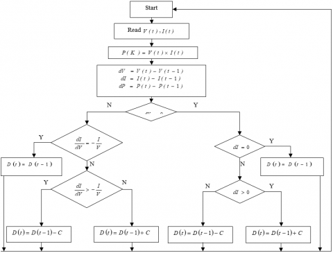
The block scheme of the fixed step size conventional Incremental Conductance method is shown in Figure 4.
Figure 4. Block scheme of the fixed step size INC method
2.4 Conventional variable step size INC method
For fixed step size conventional Incremental Conductance method, a larger step size perturbation gives a faster response. Larger step size causes a more power loss in steady state, thus resulting in a comparatively low efficiency.
This situation is the contrary for small step size perturbation; in this case a discrepancy occurs between the performance of the steady state condition and the tracking speed. In several articles [10-14] this problem has been resolved by using a variable step size perturbation algorithm.
The fixed step size perturbation is replaced by a function dependent derivative of power to voltage (dP/dV), and the algorithm is given by:
$D(t)=D(t-1) \pm N \times\left|\frac{d P}{d V}\right|$ (10)
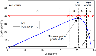
where, D(t) is the duty cycle of power converter at time t. The corresponding photovoltaic output power and the slope of the output power versus output voltage curves can be obtained as shown in Figure 5.
(P-V) and [Abs(dP/dV)]–V curves are shown in Figure 5. We can see from Figure 5 that the duty cycle D in variable step size perturbation Incremental Conductance MPPT method becomes dynamic, however, if the power point is near MPP, the MPPT method in this case delivers a small step size perturbation and if the power point is at MPP the MPPT control makes the step size equal to zero. The principle of the variable step size perturbation is shown in Table 1.
Figure 5. P-V and [Abs(dP/dV)]-V characteristic curves
Table 1. Principle of the variable step size INC
|
Position |
Left of MPP |
At MPP |
Right of MPP |
||
|
Interval |
A |
B |
0 |
C |
D |
|
Abs(dP/dV) |
Large |
Small |
0 |
Small |
Large |
Figure 6. Rapid change of irradiation levels (λ)
Figure 6 indicates the irradiation profile used in simulation. A rapid change in irradiation is applied to study the response between the conventional fixed step size INC MPPT and conventional variable step size INC MPPT method during the disturbance.
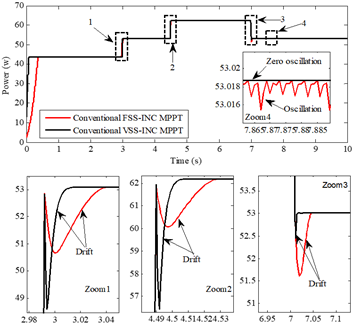
Both conventional MPPT methods are compared in terms of oscillation around of MPP and the drift problem of the tracking.
Figure 7 and Figure 8 shows the output power, the output voltage and output current for both conventional fixed step size and variable step size INC MPPT methods. From Figures 7 and 8 we can see that the conventional VSS-INC MPPT method track the maximum power point in the steady state of irradiation with best performances compared to the FSS-INC MPPT method in term of rapidity and oscillation. We also note that when the irradiation level changes rapidly both conventional INC MPPT methods suffer the drift problem in the tracking of MPP. This problem of drift is illustrated in Zoom 1-3 and 5-9 of Figure 7 and 8.
Figure 7. Output power of PV panel in rapid increase of irradiation
Figure 8. a) Output voltage of PV panel, b) Output current of PV panel: in rapid increase of irradiation
3.1 In case of rapid increase of irradiation level
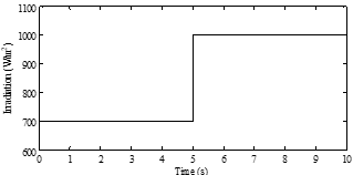
To analyze the drift problem, we applied the varying levels of irradiation increase to the simulated PV panel, as shown in Figure 9.
Figure 9. Levels of a rapid increase of irradiation (λ)
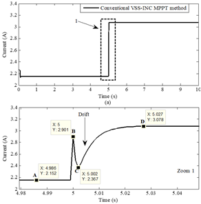
Figure 10. Output current of PV panel under irradiation change from 700W/m2 to 1000W/m2
Figure 11. Output voltage of PV panel under irradiation change from 700W/m2 to 1000W/m2
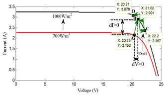
Figure 12. The movement of power point on the current-voltage curve when the irradiation increases
Figure 10 and 11 show the voltage and the current curves respectively during a rapid increase of irradiation level. From the zoom in of voltage and current curves of Figure 10 and 11 we were able to understand the phenomenon of drift based on Figure 12.
Figure 12 shows that when the irradiation level increases rapidly, the point A (20.35V 2.152A) from the (I-V)700W/m2 curve moves to the (I-V)1000W/m2 curve in the point B (21.02V 2.901A) in the right, near the point D(MPP).
At the point B the information received is:
$d V=V_{B}-V_{A}=21.02-20.35=0.67 V, d V>0$
$d I=I_{B}-I_{A}=2.901-2.152=0.749 A, d I>0$
$\frac{d I}{d V}=1.118,-\frac{I_{B}}{V_{B}}=-0.138$
Because (dI/dV)>(-IB/VB) at the point B, the conventional VSS-INC MPPT method thinks that the point B is on the left of the point D(MPP) and that's what makes it decreases the duty cycle by a large step size in opposite search direction in the tracking of MPP. The opposite search causes point B moves to point C far away from the point D(MPP) and this is a drift problem in the tracking of MPP.
3.2 In case of rapid decrease of irradiation level
We applied the rapid decrease of irradiation levels in the simulated PV panel as shown in Figure 13.
The irradiation was rapidly decreased from 1000 W/m2 to 900 W/m2 at 5s.
We obtained the Figure 15 from the information provided for Figure 14.
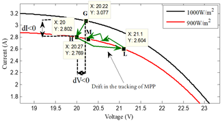
Figure 15 shows that the point G(20.22V 3.077A) exists on the highest curve (I-V)1000W/m2 move to the lower curve (I-V)800W/m2 in the point H(20V 2.802A) when a rapid decrease of irradiation occurred.
At point H:
$d V=V_{H}-V_{G}=20-20.22=-0.22 V, d V<0$
$d I=I_{H}-I_{G}=2.802-3.077=-0.275 A, d I<0$
$-\frac{I_{H}}{V_{H}}=-\frac{2.802}{20}=-0.140, \frac{d I}{d V}=\frac{-0.275}{-0.22}=1.25$
Because (dI/dV)>(-IH/VH), the conventional VSS-INC MPPT method decreases the duty cycle, what makes the search direction in the tracking of MPP is correct, however, the large step size perturbation makes the point H move to point L(21.1V 2.604A) in the right, far away from the maximum power point M(MPP).
At point L:
$d V=V_{L}-V_{H}=21.1-20=1.1 V, d V>0$
$d I=I_{L}-I_{H}=2.604-2.802=-0.198 \mathrm{A}, d I<0$
$-\frac{I_{L}}{V_{L}}=-\frac{2.604}{21.1}=-0.123, \frac{d I}{d V}=\frac{-0.198}{1.1}=-0.18$
(dI/dV<-IL/VL), Finally, the conventional VSS-INC method corrected the search direction in the tracking of MPP by increases the duty cycle and move to the maximum power point M(MPP).
Figure 13. Levels of a rapid decrease of irradiation (λ)
Figure 14. a) Output current of PV panel under irradiation change from 1000W/m2 to 900W/m2; b) Output voltage of PV panel under irradiation change from 1000W/m2 to 900W/m2
Figure 15. The movement of power point on the current-voltage curve when the irradiation decreases
The rapid change in irradiation causes the conventional VSS-INC to make false decisions; these false decisions are the error in the tracking of MPP and the larger step size perturbation given by it. The phenomenon occurs during the rapid change in irradiation is called the drift in the tracking of MPP.
To stop the drift problem in the tracking of MPP, we used dI, dV, |dλ/dt| and σ in order to capture the rapid change of irradiation, where:
$\sigma=\frac{1}{d t}$ (11)
dt: Simulation step
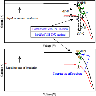
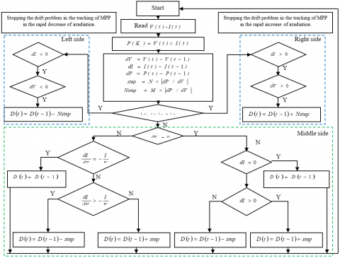
4.1 Stopping the drift problem in the rapid increase of irradiation
The method used for stopping the drift problem in the rapid increase of irradiation (λ) is as follows:
where: Nstep=M×|dP/dV|.
M: is a much smaller scale factor than N (M<<N).
Figures 16 and 17 below show a manner to stopping the drift problem in the tracking of MPP in rapid change of irradiation.
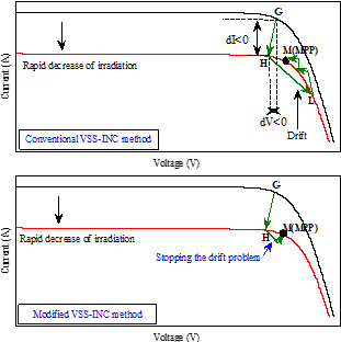
4.2 Stopping the drift problem in the rapid decrease of irradiation
When a rapid decrease of irradiation exists, we take the following solution:
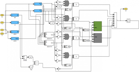
Figures 18 and 19 show respectively the block scheme and the MATLAB/SIMULINK model of modified VSS-INC method.
The modified VSS-INC method is divided into three sides as shown in Figure 18, each of which is responsible for addressing a problem that affects the effectiveness of the photovoltaic panel on supplying the maximum power where:
Figure 16. A manner to stopping the drift problem in the tracking of MPP in the rapid increase of irradiation
Figure 17. A manner to stopping the drift problem in the tracking of MPP in the rapid decrease of irradiation
Figure 18. Block scheme of modified VSS-INC method
Figure 19. MATLAB/SIMULINK model of modified VSS-INC method
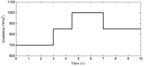
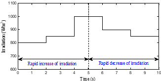
The rapid changes in irradiation were applied to the simulated PV system to see the efficacy of the modified VSS-INC method. The irradiation increased from 800W/m2 to 850W/m2 at 2s, then increases to 1000W/m2 at 4s, while decreased to 900W/m2 at 6s, then decreases to 850W/m2 at 8s as shown in Figure 20.
Figure 20. Rapid change of irradiation (λ)
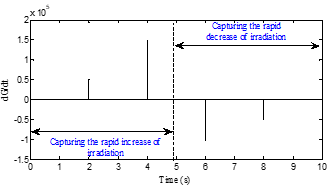
Figure 21. dG/dt characteristic curve
Figure 22. Modified VSS-INC method in the “On/Off” state
The modified VSS-INC method relies on the dG/dt to capture the rapid change of irradiation as shown in Figure 21, so that if |dG/dt|≥(1/dt), then in this case one of the two sides (left or right) of the modified VSS-INC method intervenes to address the drift problem in the tracking of MPP, if the change in irradiation is rapid increases, then the right side of the modified VSS-INC method becomes in "on" state and the left and middle side are in the "off" state to stopping the drift, but if the change in the irradiation is rapid decreases, then the right side and middle they are in the "off" state and the left side of the modified VSS-INC method becomes in the "on" state and intervenes to stopping the drift problem. In the steady irradiation, both sides (left and right) are in "off" and the middle side is "on" state as shown in Figure 22.
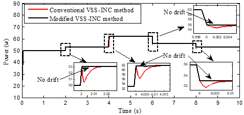
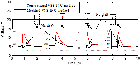
Figures 23-26 represents the simulation results performance and effectiveness of the modified VSS-INC method. The simulation between the conventional and modified VSS-INC method can be described as follows.
The duty cycle adjusted rapidly by maximum power point tracking until a stable peak output power is reached. When the irradiation rapidly changes from 800 W/m2 to 850 W/m2 and then increased again to 1000 W/m2, while decreased to 900w/m2 at 6s and then decreased back to 850w/m2, the modified VSS-INC is stopping the drift problem in the tracking of MPP by increasing the duty cycle by a small step size of rapid increases in irradiation and decreasing it by a small step size when the irradiation decreases rapidly.
Figures 23-26 illustrates that, the modified VSS-INC method stopped the drift problem compared with the conventional VSS-INC method.
Figure 23. PV output power
Figure 24. PV output current
Figure 25. PV output voltage
Figure 26. Duty cycle waveforms
This paper presents the solution to stopping the drift problem in the tracking of MPP by using the conventional VSS-INC method. The presented modified method adopted the information of (dλ/dt), change in current (dI) and change in input voltage (dV) to capture the rapid change of irradiation. A comparison between the modified method and the conventional VSS-INC method in different rapid change of irradiation is presented.
Through the simulation results the modified VSS-INC is higher than the conventional method due to stopping the drift problem.
|
I |
Output current of the photovoltaic panel |
|
V |
Output voltage of photovoltaic panel |
|
P |
Power supplied by the photovoltaic panel |
|
Iph |
Generated current |
|
ID |
Diode current |
|
Ip |
Parallel resistance current |
|
Is |
Cell reverse saturation current |
|
q |
Charge of an electron |
|
Rp |
Shunt resistance |
|
Rs |
Intrinsic series resistance of the PV module |
|
K |
Boltzmann’s constant |
|
Eg |
Band gap for silicon |
|
A |
Ideality factor for a P-N junction |
|
ISCREF |
Short circuit current at 25℃ and 1000W/m2 |
|
T |
Cell temperature (℃) |
|
ISREF |
Cell reverse saturation current at Tref |
|
Ki |
Short circuit current temperature coefficient |
|
λ |
Solar irradiation in [W/m2] |
|
C1, C2 |
Capacitor |
|
L |
Inductance |
|
RL |
Load |
APPENDIX
Table 2. Parameters of photovoltaic panel
|
Parameter |
Value |
|
Series resistance Rs |
0,015 Ω |
|
Parallel resistance Rp |
30 Ω |
|
saturation current ISCREF |
8,225.10-12 A |
|
Diode ideality factor A |
1,2 |
|
Boltzmann constant K |
1,38.10-23 J/K |
|
Electron charge q |
1,6.10-19 C |
|
Short-circuit current at standard conditions ISREF |
3.25 A |
|
Temperature at standard conditions TREF |
25 CO |
|
Open circuit voltage VOC |
24.8 V |
|
Irradiance at standard Conditions λ |
1000 W/m2 |
[1] Loukriz, A., Haddadi, M., Messalti, S. (2016). Simulation and experimental design of a new advanced variable step size Incremental Conductance MPPT algorithm for PV systems. ISA Transactions, 62: 30-38. https://doi.org/10.1016/j.isatra.2015.08.006
[2] González, A., Riba, J.R., Rius, A., Puig, R. (2015). Optimal sizing of a hybrid grid-connected photovoltaic and wind power. Applied Energy, 154: 752-762. https://doi.org/10.1016/j.apenergy.2015.04.105
[3] Liu, J.X., Laghrouche, S., Ahmed, F.S., Wack, M. (2014). PEM fuel cell air-feed system observer design for automotive applications: an adaptive numerical differentiation approach. International Journal of Hydrogen Energy, 39(30): 17210-17221. https://doi.org/10.1016/j.ijhydene.2014.08.013
[4] Ma, T., Yang, H., Lu, L. (2014). A feasibility study of a stand-alone hybrid solar-wind-battery system for a remote island. Applied Energy, 121: 149-158. https://doi.org/10.1016/j.apenergy.2014.01.090
[5] Chelli, Z., Lakehal, A., Khoualdia, T., Djeghader, Y. (2019). Study on shunt active power filter control strategies of three-phase grid-connected photovoltaic systems. Periodica Polytechnica Electrical Engineering and Computer Science, 63(3): 213-226. https://doi.org/10.3311/PPee.14025
[6] Al-Majidi, S.D., Abbod, M.F., Al-Raweshidy, H.S. (2018). A novel maximum power point tracking technique based on fuzzy logic for photovoltaic systems. International Journal of Hydrogen Energy, 43(31): 14158-14171. https://doi.org/10.1016/j.ijhydene.2018.06.002
[7] Zadeh, M.J.Z., Fathi, S.H. (2017). A new approach for photovoltaic arrays modeling and maximum power point estimation in real operating conditions. IEEE Transactions on Industrial Electronics, 64(12): 9334-9343. https://doi.org /10.1109/TIE.2017.2711571
[8] Belkaid, A., Colak, I., Kayisli, K. (2017). Implementation of a modified P&O-MPPT algorithm adapted for varying solar radiation conditions. Electrical Engineering, 99: 839-846. https://doi.org/10.1007/s00202-016-0457-3
[9] Celik, O., Teke, A. (2017). A hybrid MPPT method for grid connected photovoltaic systems under rapidly changing atmospheric conditions. Electric Power Systems Research, 152: 194-210. https://doi.org/10.1016/j.epsr.2017.07.011
[10] John, R., Mohammed, S.S., Zachariah, R. (2017). Variable step size Perturb and observe MPPT algorithm for standalone solar photovoltaic system. 2017 IEEE International Conference on Intelligent Techniques in Control, Optimization and Signal Processing (INCOS), Srivilliputhur, pp. 1-6. https://doi.org/10.1109/ITCOSP.2017.8303163
[11] Faraji, R., Chavoshian, M.R., Rouholamini, A., Naji, H.R., Fadaeinedjad, R. (2014). FPGA-based real time incremental conductance maximum power point tracking controller for photovoltaic systems. IET Power Electronics, 7(5): 1294-1304. https://doi.org/10.1049/iet-pel.2013.0603
[12] Belkaid, A., Gaubert, J.P., Gherbi, A. (2017). Design and implementation of a high-performance technique for tracking PV peak power. IET Renewable Power Generation, 11(1): 92-99. https://doi.org/10.1049/iet-rpg.2016.0023
[13] Thangavelu, A., Vairakannu, S., Parvathyshankar, D. (2017). Linear open circuit voltage-variable step-size-incremental conductance strategy-based hybrid MPPT controller for remote power applications. IET Power Electronics, 10(11): 1363-1376. https://doi.org/10.1049/iet-pel.2016.0245
[14] Yilmaz, U., Kircay, A., Borekci, S. (2018). PV system fuzzy logic MPPT method and PI control as a charge controller. Renewable and Sustainable Energy Reviews, 81: 994-1001. https://doi.org/10.1016/j.rser.2017.08.048