Khaled Djerboub* | Tayeb Allaoui | Gerard Champenois | Mouloud Denai | Chaib Habib
© 2020 IIETA. This article is published by IIETA and is licensed under the CC BY 4.0 license (http://creativecommons.org/licenses/by/4.0/).
OPEN ACCESS
Shunt Active Power Filters (SAPF) are an emerging power electronics-based technology to mitigate harmonic and improve power quality in distribution grids. The SAPF proposed in this paper is based on three-phase Flying Capacitor Inverter (FCI) with a three-cell per phase topology, which has the advantage to provide voltage stress distribution on the switches. However, controlling the voltage of floating capacitors is a challenging problem for this type of topology. In this paper, a controller based artificial neural networks optimized with particle swarm optimization (ANN-PSO) is proposed to regulate the filter currents to follow the references extracted by the method of synchronous reference frame (SRF). The simulation results showed an enhancement of the power quality with a significant reduction in the THD levels of the current source under various loading conditions, which confirms the effectiveness, and robustness of the proposed control scheme and SAPF topology.
ANN-PSO, Flying Capacitor Inverter (FCI), non-linear load, power quality, SAPF, Synchronous Reference Frame (SRF), THD
Power quality has become a serious concern for utility companies, end-users and equipment manufacturers. The problem of harmonics in the electricity grid, also known as harmonic pollution, is not a new phenomenon. Non-linear loads connected to the grid absorb non-sinusoidal currents and generate harmonic distortion, which cause several disturbances in the electricity network. These current harmonics will in turn generate harmonic voltages at various grid connection points [1, 2]. There are several harmonic reduction solutions, among these, the shunt active power filter (SAPF) has been selected.
SAPFs are connected in parallel between the source and the nonlinear load and produce harmonic components that cancel out the harmonic components of nonlinear loads. Different SAPF topologies have been proposed, which are related to the nature of the components and the methods used for harmonic identification [3, 4].
The performance of the SAPF depends largely on the isolation of the harmonic signal caused by the load. Therefore, it is imperative to identify this signal to inject its image, in amplitude and phase opposition, into the electricity network. However, the reliability of the identification method guarantees good harmonic compensation, and consequently improves the power quality. Several techniques exist among these the instantaneous reactive power theory (PQ) [5, 6], the synchronous reference frame (SRF) [7], the a-b-c reference frame [8], the synchronous detection (SD) [9]. For simplicity the synchronous reference frame algorithm (SRF) is applied here to determine the reference currents [10, 11].
Multilevel converter topologies are increasingly being used due to their high power, high-quality waveforms, better electromagnetic compatibility and lower switching losses [12].
A survey and a comparative study discuss different kinds of multilevel inverters and its applications in the filtering [13-20].
The shunt active power filter based on flying capacitor inverter (SAPF-FCI) is of interest because it has two important features: 1) it increases the voltage level, The addition of several serial switching cells reduces the voltage across the IGBTs and thus increases the filtering power and voltage value of the interconnection network [21]; 2) it increases the bandwidth. Indeed, by taking advantage of the specific degrees of freedom of the FCI, the converter's bandwidth can be improved as compared to other multi-level structures such as the Neutral Point Clamped (NPC) inverter or the cascaded inverter [22].
However, controlling the converter to balance the voltage of each capacitor can be very complex [23]. It should be noted that for a three-phase configuration, the control of each arm to balance the flying capacitor voltage, can be done independently, which reduces the complexity of the control and makes it more flexible [24, 25].
Proportional Integral (PI) and Proportional Integral Derivative (PID) controllers have been widely used to control the current loop of the SAPF due to their simplicity, ease of tuning and implementation [26]. An ANN-based control is employed for the SAPF [27, 28]. Kumar and Mahajan [29] proposed an adaptive neural network algorithm to compensate harmonics and reactive power with the PQ strategy [29]. Fuzzy Logic Controllers (FLC) with different types of membership functions are compared in the studies [30, 31]. A comparison between a PI regulator, Adaptive Neuro-Fuzzy Inference System (ANFIS) and FLC is presented [32]. However, these controllers tend to exhibit poor performance under variable operating conditions.
In this paper, the proposed controller for the SAPF current loop is based on an ANN whose parameters (weights and biases) are optimized by PSO. This control scheme is combined with simple proportional control to balance the floating capacitor voltage of FCI to achieve good performance of the SAPF-FCI and maintain the flying capacitor voltages around their references. This ensures a balanced voltage sharing on the converter switches of the FCI even under variations in the system parameters.
The remaining of the paper is organized as follows: Section 2 presents the modeling of the SAPF-FCI circuit and the SRF algorithm to extract the reference currents. Section 3 explains the operating principle of the FCI and presents the control of the flying capacitor voltage and the regulation of the DC bus voltage. In Section 4, the current loop controllers are derived. The simulation results obtained are discussed in Section 5.
2.1 SAPF-FCI topology
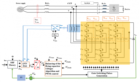
The system used in this work consists of a three-phase source, a non-linear load and a SAPF-FCI. Energy storage is provided by a capacitor (Cdc). The IGBT inverter is interfaced to the grid via three inductive filters to remove high-frequency currents.
The generation of intermediate voltage levels is based on the connection of several DC voltage sources in the form of floating capacitors, by acting on the logic states of the switching cells. The inverter structure uses IGBT switches. The topology of the SAPF-FCI is illustrated in Figure 1.
The dynamic model of SAPF-FCI in the dq frame is given in the research [33] by:
$\left\{\begin{array}{c}v_{s d}=v_{f d}-R_{f} i_{f d}-L_{f} \frac{d i_{f d}}{d t}-L_{f} \omega i_{f q} \\ v_{s q}=v_{f q}-R_{f} i_{f q}-L_{f} \frac{d i_{f q}}{d t}+L_{f} \omega i_{f d} \\ C_{d c} \frac{d V_{d c}}{d t}=S_{d} i_{f d}+S_{q} i_{f q}\end{array}\right.$ (1)
2.2 SRF algorithm for reference currents identification
The nonlinear load absorbs a current consisting of a fundamental and harmonic components. The SAPF function is to generate harmonic currents with the same amplitude but in phase opposition to those absorbed by the load. Thus, the current absorbed by the network becomes sinusoidal. It is therefore necessary to identify these harmonic currents accurately. The SRF method is applied to generate the reference current as shown in Figure 2.
The Park Transformation is used here to convert the load currents from the abc to dq coordinates (reference frame rotating with the fundamental frequency) in order to calculate the reference currents for the SAPF [34].
This transformation of the load currents from three-phase (ila, ilb, ilc) to (ilα, ilβ) is given as:
$\left[\begin{array}{c}i_{l \alpha} \\ i_{l \beta}\end{array}\right]=\sqrt{\frac{2}{3}}\left[\begin{array}{ccc}1 & -\frac{1}{2} & -\frac{1}{2} \\ 0 & \frac{\sqrt{3}}{2} & -\frac{\sqrt{3}}{2}\end{array}\right]\left[\begin{array}{c}i_{l a} \\ i_{l b} \\ i_{l c}\end{array}\right]$ (2)
The transformation of the currents ilα and ilβ to ild and ilq is given by:
$\left[\begin{array}{c}i_{l d} \\ i_{l q}\end{array}\right]=\left[\begin{array}{cc}\cos (\omega t) & \sin (\omega t) \\ -\sin (\omega t) & \cos (\omega t)\end{array}\right]\left[\begin{array}{c}i_{l \alpha} \\ i_{l \beta}\end{array}\right]$ (3)
Figure 1. Schematic diagram of the FCI-based SAPF connected to the distribution grid
The $i_{l d}$ current can be decomposed into two terms, the fundamental and harmonic. The harmonic term behaves like an alternating component and the fundamental term behaves like a continuous component, therefore:
$i_{l d}=\overline{l_{l d}}+\widetilde{i_{l d}}$ (4)
$\overline{t_{l d}}$: Fundamental component of load current in the dq frame.
$\widetilde{l_{l d}}$: Harmonic component of load current in the dq frame.
A low-pass filter (LPF) is used to separate the two components as shown in Figure 2.
The direct and quadrature reference currents $\left(i_{f d}^{*} \text { and } i_{f q}^{*}\right)$ are compared to the currents (ifd and ifq) measured at the output of the converter after a transformation in the Park reference frame. The regulator then takes the error and generates voltage references in the Park reference $\left(V_{d}^{*} \text { and } V_{q}^{*}\right)$ and after transformation into the abc frame using a PLL (Phase-Locked Loop), the reference voltages $\left(V_{a}^{*}, V_{b}^{*} \text { and } V_{c}^{*}\right)$ are deduced as shown in Figure 3 [35]. Then, a pulse width modulation (PWM) control signal applies the control signals for the converter IGBTs.
Figure 2. Block diagram for the reference currents extraction
Figure 3. Block diagram of the currents controlled by ANN-PSO
3.1 Modeling of FCI
This FCI structure is based on the series connection of switching cells between which a floating voltage source is inserted. The general diagram of an FCI arm is shown in Figure 4. It consists of pairs of switches separated by floating capacitors. The two switches in each pair must always be in an opposite state, in order to avoid a short circuit of the voltage sources. This is achieved by controlling both IGBTs with complementary signals [36].
Figure 4. Equivalent circuit for phase a of the FCI
The principle of this topology is to split the DC bus voltage into several elementary voltage sources. The operation of each switching cell is similar to that of a two-stage inverter with a voltage source equal to Vdc/p (p is the number of cells) and a current source. Each blocked switch must maintain a maximum voltage equal to Vdc/p.
The structure of a three-phase FCI is composed of three FCI arms, noting the phase index (j= a, b, c) and number of cell (p=1, 2, 3).
The variation of the voltage across capacitor Ci is related to the current ik, which is a function of the state of the adjacent cells (Cellk+1, Cellk) and the filter current if. The current ik is a function of the switch control signals S(k+1) and Sk.
$i_{k}=\left[s_{k+1}-s_{k}\right] i_{f}$ (5)
Given the capacitor value C, the equation governing the voltage Vck is written as:
$\frac{d V_{C k}}{d t}=\frac{\left[s_{k+1}-s_{k}\right]}{C_{k}} i_{f}$ (6)
Ck is the kth flying capacitor and Vck the floating voltage for k=1,2, ..., p-1.
The operation of the three-phase three-cell arms is governed by the following equation.
$\left\{\begin{array}{l}\frac{d}{d t} V_{c j 1}=\frac{1}{C_{j 1}}\left(S_{j 2}-S_{j 1}\right) i_{f j} \\ \frac{d}{d t} V_{c j 2}=\frac{1}{C_{j 2}}\left(S_{j 3}-S_{j 2}\right) i_{f j}\end{array}\right.$ (7)
3.2 Flying capacitor voltage balancing
The control method proposed by Hemici et al. [37], consists of adding a compensation term of the duty cycle, which results from the comparison of the flying capacitor voltage with the desired reference. This method allows direct control of the current. The average value of the current of the kth flying capacitor is:
$i_{k}=\left(u_{k+1}-u_{k}\right) i_{f}$ (8)
By adjusting the difference in the duty cycle (uk+1 - uk), the voltage gap is filled in one pulse period. The following relationship is obtained.
$i_{k}=c_{k} \frac{\frac{k V_{d c}}{p}-V_{c k}}{T}$ (9)
From Eqns. (8) and (9), the desired value is obtained as:
$u_{k+1}-u_{k}=\frac{C_{k}}{T i_{f}}\left(\frac{k V_{d c}}{p}-V_{c k}\right)$ (10)
where, T is the switching period.
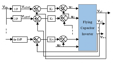
It should be noted that there are p control variables, p duty cycles) and (p-1) capacitor voltages to be controlled. This implies that the additional control variable will be chosen constant according to the operating point or will be used to control an output variable of the converter. The focus here is to control of the voltages Vck, the input variable is constant and the duty cycle up is chosen arbitrarily. The synoptic of the control law is shown in Figure 5.
Figure 5. Control of the flying capacitor voltage
where,
VCk,ref: the kth desired references of the floating voltage equal to $k V_{d c} / p$.
K = proportional gain equal to Ck if/T.
3.3 PWM control
The control signals of the cells switches are generated by a PWM which consists in using the intersections of a reference signals $\left(V_{a}^{*}, V_{b}^{*} \text { and } V_{c}^{*}\right)$ with the triangular signals defined by Eq. (11).
$P_{k}=\frac{1}{2}\left\{\frac{2}{\pi} \sin ^{-1}\left[\sin \left(\frac{2 \pi}{p} t-\varphi_{j k}+\frac{\pi}{2}\right)\right]+1\right\}$ (11)
The angle φjk is the same for all Pk signals and is given by:
$\varphi_{j k}=(k-1) \frac{2 \pi}{p}$ (12)
The control signal ujk is obtained as follows:
$\left\{\begin{array}{c}\text { If reference signal } \geq P_{k} \text { then } u_{j k}=1 \\ \text { Else } u_{j k}=0\end{array}\right.$
3.4 DC bus voltage regulation
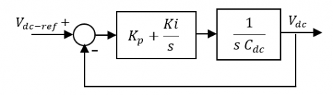
A basic PI control loop for the DC bus voltage is shown in Figure 6.
Figure 6. DC voltage regulation with PI
Using the control design method proposed by Rahmani et al. [38], the PI controller gains are obtained as follows:
$\begin{aligned} K_{p} &=2 \xi \omega_{n} C_{d c} \\ K_{i} &=C_{d c} \omega_{n}^{2} \end{aligned}$ (13)
4.1 Artificial Neural Network (ANN)
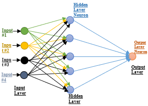
In general, a formal neuron is a processing element with n inputs x1, x2, ..., xj, xn(Which are the external inputs or outputs of the other neurons) and one or more outputs shown in Figure 7. The neuron calculates the sum of its inputs and this value passes through the activation function to produce its output Yi [39].
$Y_{i}=f_{i}\left(\sum_{j=1}^{n} w_{i j} \cdot X_{j}+b_{i}\right)$ (14)
where, wij is the connection weight between the input and output neuron, bi is the bias of the neuron, and f is the activation function, which determines the characteristics of the neural network.
Figure 7. Artificial Neural Network (ANN) architecture
The learning process of neural networks is the modification of the connection weights (including biases) and very rarely the number of layers number and neurons, in order to adapt to the pattern of data presented at its inputs.
4.2 Overview of Particle Swarm Optimization (PSO)
The Particle Swarm Optimization (PSO) algorithm in its global version is initialized by a population of potential random solutions interpreted as particles moving in the search space. Each of the neighboring particles being considered has a speed and a small memory, allowing it to remember its best performance, in position and value. The performance of each particle is measured according to a predefined objective function related to the problem to be solved [40]. The velocity at iteration (t+1) for each particle is a linear combination of the position and velocity at iteration t and the distances that separate the current position of the particle from its previous best position and best overall position, respectively. The equations formalizing the motion of the particles are given by Eqns. (15) and (16).
$v_{i}(t)=w, v_{i}(t-1)+c_{1} \cdot r_{1} \cdot\left(P_{\text {lbest }}(t-1)-x_{i}(t-1)\right)+c_{2} \cdot r_{2} \cdot\left(G_{\text {best }}-x_{1}(t-1)\right)$ (15)
$x_{i}(t)=x_{i}(t-1)+v_{i}(t)$ (16)
where,
xi represents the solution (position) of the ith particle.
vi is the velocity (speed) of the ith particle.
Pibestrepresents the ith best solution (position) of particle i.
Gbest is the best overall solution (position) of the group.
w is called constant inertia coefficient, c1 and c2 are two constants called acceleration coefficients, r1 and r2 are two random numbers in the interval [0,1] at each iteration and for each dimension.
Eqns. (15) and (16) are iterated until the convergence is reached [41].
4.3 Training the artificial neural networks by PSO algorithm
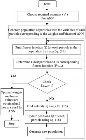
ANN training aims to obtain optimal values for the weights and biases of the network. Different techniques are used to find the appropriate values of weights and biases of the ANN. In this paper, PSO algorithm used. The algorithm can be summarized in the following steps:
Step 1: Random initialization of all local positions $X_{i}$ (weights and biases).
Step 2: Evaluate the fitness function given by Eq. (17) of each particle f(Xi) of initialized particles and set local positions Pibest and global position Gbest.
$f=\sum \sqrt{(\text {target}-\text {actuel output})^{2}}$ (17)
Step 3: Update all the best local Pibest positions.
Step 4: Evaluate the fitness function new local best and
If f(Pbest) < f(Gbest) then Gbest = Pbest.
Step 5: Update of the weights and biases of the neural networks using Eq. (15) and Eq. (16).
Step 6: if the stop criterion is satisfied then stop otherwise go to step 2 and present the weights and biases for a new iteration.
Convergence is reached when the synaptic coefficients stabilize around a final value and the total square error of the network is less than a threshold. In addition, it is possible to stop the learning by setting a limit on the number of iterations. Figure 8 shows the flowchart for the training algorithm.
Figure 8. Flowchart of the training the ANN using PSO algorithm
The current controllers and SRF detection method have been tested on a distorted waveform produced by a nonlinear load (diode bridge rectifier with RL load) and three-cell FCI inverter used SAPF. The simulation is conducted using the parameters given in Table 1.
Table 1. Parameters values of the simulated system
|
Parameter |
value |
|
Source voltage and frequency Source impedance Rs, Ls Line impedance Rl, Ll Coupling impedance Rf, Lf DC bus voltage DC Bus capacitance Load impedance Rch, Lch Flying capacitor Cells number Switching frequency Sampling time |
220V, 50Hz 1 mΩ, 1mH 1 mΩ, 1mH 1mΩ, 0.8mH 800 V 5mF 10Ω, 10mH 0.1mF 3 10kHz 10-6s |
To confirm the convergence conditions of the PSO algorithm based on the selected parameters, the algorithm was tested for the values of the social and cognitive coefficients c1and c2 respectively as well as its inertia factors wmax and wmin which are given in Table 2. The details of ANN architecture of the proposed controllers are also presented in Table 2.
Table 2. ANN-PSO parameters used in the model
|
Parameter |
value |
|
PSO algorithm: swarm size Maximum iteration Inertia coefficients [wmax, wmin] Acceleration coefficients [c1, c2] |
40 100 [0.9,0.4] [2, 2] |
|
ANN network: Maximum epochs Learning rate Performance goal No of neurons in hidden layer Activation function (hidden/output) |
500 0.05 0.0001 3 tansig/purelin |
Figure 9 show that ANN-PSO controllers give almost the same results as PI controllers. The load current has a non-sinusoidal waveform, with a THD of 24.14%. The control strategy adopted is based on the synchronous detection of reference currents as it allows a good extraction of reference currents. The injection of the compensation current into the grid makes the grid current sinusoidal with a very low THD of 1.05%.
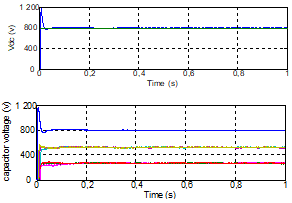
The DC bus voltage and the voltages across the floating capacitors are represented in Figure 10. After a transient, the DC bus and floating capacitor voltages reach their final values Vdc, Vdc/3, 2Vdc/3, respectively.
Figure 9. Load and source currents waveforms with ANN-PSO controllers
Figure 10. DC-bus and flying capacitors voltages
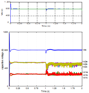
To assess the robustness of ANN-PSO controller under load variations the following test was performed. At time $t=1 s$, the resistance of the non-linear load is decreased from 20 Ω to 10 Ω. The results are shown in Figures 11 and 12.
Figure 11. Load and source currents waveforms with ANN-PSO controllers under varying load conditions
Figure 11 shows that the source current waveform remains sinusoidal during load variations. The performance of the ANN-PSO controller and its ability to eliminate harmonics is better than the PI controller. Indeed, the THD is reduced significantly from 24.14% to 1.12% for ANN-PSO controller and to 1.74% for PI controller, which demonstrates the robustness of the proposed ANN-PSO controller.
Figure 12. DC bus and flying capacitors voltages under varying load conditions
The PI regulator keeps the DC bus voltage at its reference value (Vdc-ref=800 V) under load variation. The flying capacitor voltage perfectly follows their references (Vdc/3, 2Vdc/3) with a short transient response as shown in Figure 12.
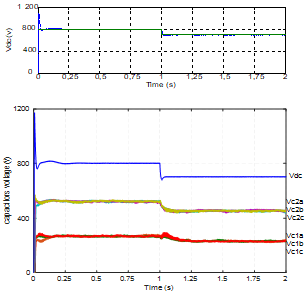
To test the robustness of the ANN-PSO control to DC bus voltage variations, at time t=1 s, the DC bus voltage is decreased from 800 V to 700 V. The results of this simulation scenario are shown in Figures 13 and 14.
Figure 13 shows the load and source currents waveforms during Vdc variations. It can be observed that the ANN-PSO controller leads to a better performance than the PI. For ANN-PSO controllers, the THD is reduced to 1.06%, while PI it is reduced to 1.34%.
Figure 14 shows that the DC bus voltage reaches its new value of 700 V. It should be noted that the flying capacitor voltages perfectly follows their new references.
Figure 13. Load and source currents waveforms with ANN-PSO controllers under varying DC bus voltage
Figure 14. DC-bus and flying capacitors voltages under varying DC bus voltage
Table 3. Total harmonic distortion of source currents
|
controller |
PI |
ANN-PSO |
|
Without SAPF |
24.14% |
24.14% |
|
With SAPF |
1.06% |
1.05% |
|
With SAPF under load variation |
1.73% |
1.12% |
|
With SAPF under Vdc variation |
1.34% |
1.06% |
Table 3 shows a comparison of the THD of the load current and the THD of the source current achieved by the two controllers. ANN-PSO controller leads to a significantly better performance than the PI regulator during the variation of the load or the variation of the DC bus voltage.
This paper proposed an effective current control scheme for a Shunt Active Power Filter (SAPF) with a Flying-Capacitor Multilevel Inverter (FCI) topology. The controller is based on Artificial Neural Networks (ANN) trained with Particle Swarm Optimization (PSO). The reference currents of the SAPF have been extracted using the Synchronous Reference Frame (SRF) theory. The overall model and control scheme have been developed under MATLAB/Simulink.
The simulation results obtained in steady state have shown that both ANN-PSO and PI controllers lead to similar performance yielding a quasi-sinusoidal source current with a very low THD (1.05%).
The robustness of these controllers has been tested by applying a change of 100% in the load and a variation of 100 V in the DC bus voltage. These results have shown that ANN-PSO controller has better performance as compared to PI control in terms of THD level, and improved transient response with a perfect steady-state tracking of the references for both the DC bus and floating voltages of the flying capacitors of the three-cell inverter.
|
IGBT |
Insulated Gate Bipolar Transistor |
|
PWM |
Pulse Width Modulation |
|
PLL PI il is if |
Phased Locked Loop Proportional-Integral load current source current filter current |
|
Greek symbols |
|
|
ξ |
damping ratio |
|
ωn |
natural frequency |
|
Subscripts |
|
|
1; 2 j: a; b; c dc d; q α, β |
flying capacitor 1, 2 phase a, b, or c of the converter DC-bu d (direct), q (quadrature) axis stationary two-axis reference frame |
[1] Akagi, H. (1996). New trends in active filters for power conditioning. IEEE Transactions on Industry Applications, 32(6): 1312-1322. http://dx.doi.org/10.1109/28.556633
[2] Singh, M., Chandra, A. (2013). Real-time implementation of ANFIS control for renewable interfacing inverter in 3P4W distribution network. IEEE Transactions on Industrial Electronics, 60(1): 121-128. http://dx.doi.org/10.1109/TIE.2012.2186103
[3] Kalra, K.P.K., Shah, M.T. (2017). Simulation analysis of two-level and three-level (NPC) converter based SAPF for different current control schemes. 2017 Recent Developments in Control, Automation & Power Engineering (RDCAPE), Noida, pp. 212-219. http://dx.doi.org/10.1109/RDCAPE.2017.8358269
[4] He, J., Demerdash, N.A.O., Weise, N., Katebi, R. (2017). A fast on-line diagnostic method for open-circuit switch faults in SiC-MOSFET-based T-type multilevel inverters. IEEE Transactions on Industry Applications, 53(3): 2948-2958. http://dx.doi.org/10.1109/TIA.2016.2647720
[5] Afonso, J., Couto, C., Martins, J. (2000). Active filters with control based on the p–q theory. IEEE Industrial Electronics Society Newsletter, 47(3): 5-10.
[6] Popescu, M., Bitoleanu, A., Suru, V. (2013). A DSP-based implementation of the p-q theory in active power filtering under nonideal voltage conditions. IEEE Transactions on Industrial Informatics, 9(2): 880-889. http://dx.doi.org/10.1109/TII.2012.2223223
[7] Zhang, B. (2007). The method based on a generalized DQK coordinate transform for current detection of an active power filter and power system. 30th Annual IEEE Power Electronics Specialists Conference. Record. (Cat. No.99CH36321), Charleston, SC, USA, pp. 242-248. http://dx.doi.org/10.1109/PESC.1999.789010
[8] Chang, G.W., Chen, S.K. (2000). An a-b-c reference frame-based control strategy for the three-phase four-wire shunt active power filter. Ninth International Conference on Harmonics and Quality of Power. Proceedings (Cat. No.00EX441), Orlando, FL, USA, pp. 26-29. http://dx.doi.org/10.1109/ICHQP.2000.896993
[9] Chen, C.L., Lin, C.E., Huang, C.L. (1994). An active filter for unbalanced three-phase system using synchronous detection method. Proceedings of 1994 Power Electronics Specialist Conference - PESC’94, Taipei, Taiwan, pp. 1451-1455. http://dx.doi.org/10.1109/PESC.1994.373875
[10] Bhattacharya, S., Divan, D. (1995). Synchronous frame based controller implementation for a hybrid series active filter system. IAS ’95. Conference Record of the 1995 IEEE Industry Applications Conference Thirtieth IAS Annual Meeting, Orlando, FL, USA, pp. 2531-2540. http://dx.doi.org/10.1109/IAS.1995.530625
[11] Hoon, Y., Radzi, M.A.M., Hassan, M.K., Mailah, N.F. (2018). Operation of three-level inverter-based shunt active power filter under nonideal grid voltage conditions with dual fundamental component extraction. IEEE Transactions on Power Electronics, 33(9): 7558-7570. http://dx.doi.org/10.1109/TPEL.2017.2766268
[12] Meynard, T.A., Foch, H. (1992). Multi-level conversion: high voltage choppers and voltage-source inverters. PESC `92 Record. 23rd Annual IEEE Power Electronics Specialists Conference, Toledo, Spain, pp. 397-403. http://dx.doi.org/10.1109/PESC.1992.254717
[13] Bharathi, C.R. (2019). Design of new asymmetrical cascaded multilevel inverter with reduced number of switches. European Journal of Electrical Engineering, 21(6): 547-552.
https://doi.org/10.18280/ejee.210609
[14] Hu, J.F., Zhang, L., Watkins, S.J. (2008). Active power filtering by a flying-capacitor multilevel inverter with capacitor voltage balance. 2008 IEEE International Symposium on Industrial Electronics, Cambridge, pp. 2348-2352. http://dx.doi.org/10.1109/ISIE.2008.4677285
[15] Geethalakshmi, B., Kavitha, M., Delhibabu, K. (2010). Harmonic compensation using multilevel inverter based shunt active power filter. 2010 Joint International Conference on Power Electronics, Drives and Energy Systems & 2010 Power, India, pp. 1-6. http://dx.doi.org/10.1109/PEDES.2010.5712466
[16] Vodyakho, O., Hackstein, D., Steimel, A., Kim, T. (2008). Novel direct current-space-vector control for shunt active power filters based on the three-level inverter. IEEE Transactions on Power Electronics, 23(4): 1668-1678. http://dx.doi.org/10.1109/TPEL.2008.925181
[17] Pouresmaeil, E., Montesinos-Miracle, D., Gomis-Bellmunt, O., Sudrià-Andreu, A. (2010). Instantaneous active and reactive current control technique of shunt active power filter based on the three-level NPC inverter. European Transactions on Electrical Power, 21(7): 2007-2022. http://dx.doi.org/10.1002/etep.536
[18] Rodriguez, J., Lai, J.S., Fang, Z.P. (2002). Multilevel inverters: A survey of topologies, controls, and applications. IEEE Transactions on Industrial Electronics, 49(4): 724-738. http://dx.doi.org/10.1109/TIE.2002.801052
[19] Kouro, S., Malinowski, M., Gopakumar, K., Pou, J., Franquelo, L.G., Bin Wu, Leon, J.I. (2010). Recent Advances and Industrial Applications of Multilevel Converters. IEEE Transactions on Industrial Electronics, 57(8): 2553-2580. http://dx.doi.org/10.1109/TIE.2010.2049719
[20] Malinowski, M., Gopakumar, K., Rodriguez, J., Pérez, M. A. (2010). A survey on cascaded multilevel inverters. IEEE Transactions on Industrial Electronics, 57(7): 2197-2206. http://dx.doi.org/10.1109/TIE.2009.2030767
[21] Defay, F., Llor, A.M., Fadel, M. (2007). An active power filter using a sensorless muticell inverter. 2007 IEEE International Symposium on Industrial Electronics, Vigo, pp. 679-684. http://dx.doi.org/10.1109/ISIE.2007.4374678
[22] Martins, C.A., Roboam, X., Meynard, T.A., Carvalho, A. S. (2002). Switching frequency imposition and ripple reduction in DTC drives by using a multilevel converter. IEEE Transactions on Power Electronics, 17(2): 286-297. http://dx.doi.org/10.1109/63.988948
[23] Hu, J., Zhang, L., Watkins, S.J. (2008). Active power filtering by a flying-capacitor multilevel inverter with capacitor voltage balance. 2008 IEEE International Symposium on Industrial Electronics, Cambridge, pp. 2348-2352. http://dx.doi.org/10.1109/ISIE.2008.4677285
[24] Meynard, T.A., Fadel, M., Aouda, N. (1997). Modeling of multilevel converters. IEEE Transactions on Industrial Electronics, 44(3): 356-364. http://dx.doi.org/10.1109/41.585833
[25] Sadigh, A.K., Dargahi, V., Corzine, K.A. (2017). New active capacitor voltage balancing method for flying capacitor multicell converter based on logic-form-equations. IEEE Transactions on Industrial Electronics, 64(5): 3467-3478. http://dx.doi.org/10.1109/TIE.2016.2614267
[26] Tsengenes, G., Adamidis, G. (2011). Shunt active power filter control using fuzzy logic controllers. 2011 IEEE International Symposium on Industrial Electronics, Gdansk, pp. 365-371. http://dx.doi.org/10.1109/ISIE.2011.5984186
[27] Vazquez, J.R., Salmeron, P. (2003). Active power filter control using neural network technologies. IEE Proceedings - Electric Power Applications, 150(2): 139. http://dx.doi.org/10.1049/ip-epa:20030009
[28] Singh, B., Chandra, A., Al-Haddad, K. (1999). Computer-aided modeling and simulation of active power filters. Electric Machines & Power Systems, 27(11): 1227-1241. https://doi.org/10.1080/073135699268687
[29] Kumar, P., Mahajan, A. (2009). Soft computing techniques for the control of an active power filter. IEEE Transactions on Power Delivery, 24(1): 452-461. http://dx.doi.org/10.1109/TPWRD.2008.2005881
[30] Singh, B., Solanki, J. (2009). An implementation of an adaptive control algorithm for a three-phase shunt active filter. IEEE Transactions on Industrial Electronics, 56(8): 2811-2820. http://dx.doi.org/10.1109/TIE.2009.2014367
[31] Mikkili, S., Panda, A.K. (2012). Real-time implementation of PI and fuzzy logic controllers based shunt active filter control strategies for power quality improvement. International Journal of Electrical Power & Energy Systems, 43(1): 1114-1126. http://dx.doi.org/10.1016/j.ijepes.2012.06.045
[32] Mikkili, S., Panda, A.K. (2012). Simulation and real-time implementation of shunt active filter id–iq control strategy for mitigation of harmonics with different fuzzy membership functions. IET Power Electronics, 5(9): 1856-1872. http://dx.doi.org/10.1049/iet-pel.2012.0254
[33] Mendalek, N., Al-Haddad, K., Dessaint, L.A., Fnaiech, F. (2003). Nonlinear control technique to enhance dynamic performance of a shunt active power filter. IEE Proceedings - Electric Power Applications, 150(4): 373-379. http://dx.doi.org/10.1049/ip-epa:20030488
[34] Panda, A.K., Patel, R. (2015). Adaptive hysteresis and fuzzy logic controlled-based shunt active power filter resistant to shoot-through phenomenon. IET Power Electronics, 8(10): 1963-1977. http://dx.doi.org/10.1049/iet-pel.2014.0680
[35] Rolim, L.G.B., Costa Jr, D.R., Aredes, M. (2006). Analysis and software implementation of a robust synchronizing PLL circuit. IEEE Transactions on Industrial Electronics, 53(6): 1919-1926. http://dx.doi.org/10.1109/ISIE.2003.1267261
[36] Meynard, T.A., Foch, H., Thomas, P., Courault, J., Jakob, R., Nahrstaedt, M. (2002). Multicell converters: Basic concepts and industry applications. IEEE Transactions on Industrial Electronics, 49(5): 955-964. http://dx.doi.org/10.1109/TIE.2002.803174
[37] Hemici, K., Zegaoui, A., Djahbar, A., Bokhtache, A.A., Kessaissia, F.Z., Allouache, H., Aillerie, M. (2017). Sliding mode control for a three phase multicellular inverter dedicated to renewable energy systems. AIP Conference Proceedings. http://dx.doi.org/10.1063/1.4976280
[38] Rahmani, S., Mendalek, N., Al-Haddad, K. (2010). Experimental design of a nonlinear control technique for three-phase shunt active power filter. IEEE Transactions on Industrial Electronics, 57(10): 3364-3375. http://dx.doi.org/10.1109/TIE.2009.2038945
[39] Qasim, M., Khadkikar, V. (2014). Application of artificial neural networks for shunt active power filter control. IEEE Transactions on Industrial Informatics, 10(3): 1765-1774. http://dx.doi.org/10.1109/TII.2014.2322580
[40] Del Valle, Y., Venayagamoorthy, G.K., Mohagheghi, S., Hernandez, J.C., Harley, R.G. (2008). Particle swarm optimization: Basic concepts, variants and applications in power systems. IEEE Transactions on Evolutionary Computation, 12(2): 171-195. http://dx.doi.org/10.1109/TEVC.2007.896686
[41] Xiao, P., Venayagamoorthy, G.K., Corzine, K.A. (2007). Combined training of recurrent neural networks with particle swarm optimization and backpropagation algorithms for impedance identification. 2007 IEEE Swarm Intelligence Symposium, Honolulu, HI, pp. 9-15. http://dx.doi.org/10.1109/SIS.2007.368020