Cheikh Samra | Zebbar Djallel* | Kherris Sahraoui | Stitou Driss | Benchatti Ahmed
OPEN ACCESS
This work is devoted to the study of a new power plant with multiple cascaded sorption heat transformers and power generation devices. The plant is powered from flat thermal solar collectors. The project objective is to of meet the electricity needs of up to 100 households, i.e. the equivalent of 10 kWe. Two assembly schemes are proposed. The first one includes an Ericsson heat engine as a mechanical work conversion device. While the second includes a heat to mechanical conversion machine operating according to the subcritical and supercritical ORC (Organic Rankine Cycles). The mathematical modeling revealed that mechanical work production is quite possible by the second power plant configuration. The thermal efficiencies obtained for the absorption and adsorption heat-transformers are equal to 59.6% and 10.4% respectively. For the two ORC subcritical and supercritical these values are equal to 5.64% and 7.02% respectively for the low heat source temperature TSC equal to 343 K. The concept analysis clearly shows the feasibility of the second configuration which can satisfy the specified power needs of 10 kWe from thermal solar collectors at 358 K. The maximal overall conversion efficiency of this second configuration reaches 18%, which is much above photovoltaic conversion systems efficiency.
absorption, adsorption, Joule cycle, Organic Rankine Cycle, power generation, heat transformer, temperature, solar collector, working fluid
Considerable efforts must be made to limit the fatal depletion consequences of global fossil and thermonuclear energy resources, climate change and population growth. To do this correctly, it would be advisable to follow simultaneously the following directions: - the best management of existing resources, - improvement and implementation of high energy efficiency power plants and – finally, the valorization of the different thermal rejections and the popularization of alternative and renewable energies use. The exploitation of different alternative energy sources such as thermal energy is growing because of many advantages, among which, their presence in large quantities and variety of origins. Thermal energy is not only available in the natural elements (sun, geothermal, ..), but it can also come from many processes resulting from human activity (industry, ..). However, renewable thermal energy use is not as widespread because of its potential that remains less attractive for different applications. In this context, recovery and up-grade of low-potential heat energy are therefore a promising way for reducing fossil energy consumption and energy optimization of systems. The best way to exploit the energy potential of the abundant and not much attractive heat sources is to use sorption thermal transformation processes that are very attractive in terms of energy and economy.
A new concept of thermal cascade assembly of several heat transformers of the same or different types is reported in [1-3]. According to this, two different terminologies have been reported in the literature. The first term is multi-stage (double stage and triple stage) which indicates the number of times that the heat is introduced at the hot source. The second one is the term multi-effect (double effect, triple effect...) which indicates the number of pressure levels. According to the first terminology, heat transformers with two, three or more stages can be coupled in three different ways. The first is to connect the absorber of the first stage to the evaporator of the second stage and the absorber of the second stage to the evaporator of the third stage and so on [4]. This configuration provides maximum temperature rise over other configurations [5]. The second way is to couple the absorber of the first stage with the generator of the second stage, which will achieve a relatively high COP but relatively lower temperatures. The third way is to deal out the heat delivered by the absorber of the first stage to the generator and the evaporator of the second stage. This combination allows reaching a relatively high maximum temperature but with a lower performance. This last way is interesting solely in case of low heat source potential and where the high temperature requirements are too great [6].
Another version of dual stage absorption heat transformer has recently been proposed by Yang et al. [7]. It provides greater system efficiency at the industrial scale and consists of two absorption heat transformers. The first one operates with the LiBr / H2O couple, as for the second with the NH3 / H2O couple. In addition to that, the source of low potential is divided into two heat flows. According to the second terminology (multi-effect heat transformer), several studies [8, 9] have been carried out.
The implementation of thermal cascade of several thermochemical cycles according to the two terminologies (multi-stage or multi-effects cycles) could raise the temperature level of the driving source and thus improve the energy performance. An identical concept to the thermal cascade proposed in this work has been reported by Ziegler et al. [10] for heat pumps called a multi-effect heat pump.
A similar concept has been proposed by Stitou et al. [11]. The authors suggest different possible configurations of the trithermal machine by coupling the liquid-gas absorption process with a reversible chemical reaction process to obtain cooling at 5 °C.
The present study looks at the feasibility of a new cascade concept consisting of sorption heat transformers fed from low potential natural sources. The thermal energy upgraded at the outlet of the cascade is converted into mechanical energy. These sorption systems are the combination of several physicochemical processes and can be divided into two categories. The first one consists of gas absorption by a liquid solution, while the second category implies the gas adsorption by a solid with a heat release called isosteric heat of adsorption. This upgraded heat will subsequently be converted into mechanical energy by conversion devices. In fact, the targeted power segment is the one that covers domestic needs, such as in isolated sites. In this context, it is worth to mention some pilot projects that show the feasibility of similar small power systems. A micro solar power station project has been realized as part of the Solar Power System (SPS) research program. It is a hybrid system based on hermetic volumetric expanders-generators of "scroll" type operating with superposed Rankine cycles where the analysis of the project demonstrates clearly the feasibility of the concept, its correct operation over a wide range of power range from a few Watts to a few kWe [12].
A micro thermodynamic solar power plant by Schneider Electric expects autonomous production of electricity by a Stirling engine in isolated sites of developing countries. A typical consumption of 200 kWh of electrical energy per day for 100 households was identified in the project with a power peak of 10 kW. It will have to satisfy well defined specifications in terms of needs to be satisfied and all-round constraints to be respected [13].
In the field of micro power, the conversion of thermal renewable energy into mechanical energy does not seem to have the same development as for large powers. This success lack, however, for a very important power segment (residential and tertiary), is due to systems absence adapted to this power segment, although volumetric energy conversion machines are well adapted to it. Especially, hot-air engines or engines with external heat input (Stirling and Ericsson) which are presented as being a very good solution for the conversion of thermal energy into mechanical one. Moreover, the Stirling engine is one of the few external heat transfer engines marketed for small power applications.
The ORC using an organic fluid as a working fluid instead of the conventional water vapor fluid is also used for heat to mechanical conversion. The organic fluid evaporates at medium and low temperatures below 300 °C. This gives relatively better reliability and efficiency to small power plants. Finally, it should be pointed out that power plants with scroll turbines operating on ORC in the low temperature range between 120 and 200 ° C are already available on the market [14].
To achieve the pre-established objectives, two power plants configurations are proposed in this study to meet domestic needs of electricity in isolated regions not connected to electricity network (urban agglomeration of 600 to 700 peoples) in developing countries, mainly in Africa with power peak requirement around 10 kWe fed from low potential source as flat solar collectors with surface temperature in the range of 323 to 363 K.
The paper is organized as follows: Section 2 describes two power plant configurations with cascaded sorption heat transformers and micro-power generation devices followed by the presentation of the developed mathematical model with all equations and fundamental laws specific to each compartment of the proposed power plants in Section 3. The main results are presented and discussed in Section 4. Finally the main conclusions drawn are presented in Section 5.
2.1 The first configuration
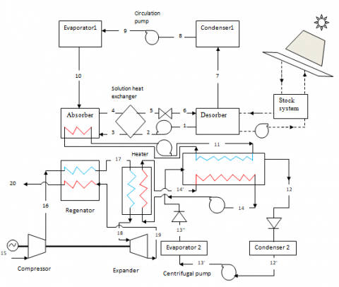
The first configuration schematic diagram of the proposed power plant is shown in Figure 1. It consists of two subsystems. The first is used to upgrade heat coming from low-potential heat source. It is composed of two single-effect heat transformers with different operating cycles. The first is an AbHT operating with LiBr / water working fluid which is the best performing pair for this system where the second is an AdHT operating with physical adsorption cycle using the zeolite 13X / water pair. The latter is considered as a suitable pair and adopted for this application with heat upgrading capability from 80 to 150 °C [15]. This cycle includes adsorption and desorption phases.
This first subsystem is connected to the second one which is designed for heat conversion and power generation from the heat upgraded by the first subsystem. It is composed of a reciprocating heat engine operating according to Brayton cycle with external heat input. The heat engine is composed of an expansion cylinder, a compression cylinder and a heater (Ht1) supplied with heat from AdHT adsorber. It may be equipped with a regenerator. In the proposed machine several fluids can be used such as air, helium (He), dihydrogen (H2) and dinitrogen (N2). Depending on the fluid used, the cycle will be open or closed.
2.2 The second configuration
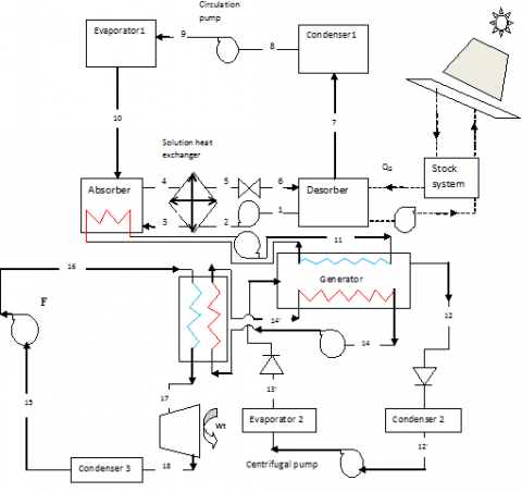
The second configuration schematic diagram of the proposed power plant is shown in Figure 2. This power plant includes two single-effect heat-transformers coupled in series similar to the ones in the first configuration. The adsorber of the last heat transformer feed the ORC of the converting device. Compared to the traditional cycle that uses water as a working fluid and requires high temperature thermal sources, the ORC uses organic working fluids suitable for power generation from low potential heat sources. According to the ORC operational conditions two configurations are possible. The first one includes the subcritical cycle which is a standard cycle without and with heat recuperator used in the case where the steam of the fluid leaving the turbine is sufficiently hot, which allows to improve the performance of ORC. However, the second configuration includes a supercritical cycle which is most often used in case where the working fluid critical temperature is much lower than that of the hot source. Nevertheless, according to several authors, investigations on the ORC supercritical cycles are of great interest because of their relatively high efficiency [16].
In this study, fluids such as SES36 and hexane reported by Quoilin et al. [17] were chosen because of their thermo-physical, safety and environmental properties. In addition, other criteria such as hot source temperature level adopted for the two chosen fluids have coveted this choice.
The preselection study has allowed making a comparison between the different working fluids and selecting the appropriate fluid and suitable operating cycle.
Figure 1. The first configuration schematic diagram
Figure 2. The second configuration schematic diagram
Table 1. The used mathematical expressions
|
Compartment |
Mass balance |
Energy balance |
Efficiencies |
|
Expression |
$\sum{{{{\dot{m}}}_{out}}}=\sum{{{{\dot{m}}}_{in}}}$ |
$\sum{{{{\dot{m}}}_{out}}{{h}_{out}}=\sum{{{{\dot{m}}}_{in}}{{h}_{in}}}}$ |
Energy output/Energy supplied |
|
Absorber heat transformer |
|||
|
Generator (or desorber) |
ṁ6=ṁ 1 + ṁ 7 |
QG1 = ṁ 7 h7 + ṁ 1 h1 – ṁ 6 h6 |
$COP_{AbHT}=\frac{Q_{u1}}{Q_{E1}+Q_{G1}+∑Ẇ_p}$ $ COP_{rev1}=\frac{T_{U1}*(T_{C1}-T_{E1})}{T_{E1}*(T_{C1}-T_{U1})} $ $F=\frac{{{{\dot{m}}}_{3}}}{{{{\dot{m}}}_{10}}}$ $\eta_{AbHT}=\frac{COP_{AbHT}}{COP_{rev1}}$ |
|
Evaporator1 |
ṁ 9=ṁ 10 |
QE1 = ṁ 10*(h10 - h9) |
|
|
Absorber |
ṁ 3+ṁ 10=ṁ 4 |
Qu1 =ṁ 3 h3 – ṁ 4 h4+ṁ 10 h10 |
|
|
Condenser1 |
ṁ 7 = ṁ 8 |
QC=ṁ 8 *(h8-h7) |
|
|
Solution heat exchanger |
ṁ 4=ṁ 5 ṁ 2=ṁ 3 |
QHX= ṁ 2*(h3ʹ-h2)=ṁ 4*(h4-h5) QHX= ε* ṁ 2*(h4 -h2) |
|
|
Pump 1 |
ṁ 9 = ṁ 8 |
ẆP1 = ṁ 8*(h9 – h8) |
|
|
Pump 2 |
ṁ 2 = ṁ 1 |
ẆP2=ṁ 1*(h2 – h1) |
|
|
Expander |
ṁ 5 = ṁ 6 |
/ |
|
|
Adsorber heat transformer |
|||
|
Generator |
/ |
${{Q}_{G2}}={{h}_{12}}-{{h}_{11}}+\int_{X11}^{X12}{{{H}_{is}}dx}$ |
$COP_{AdHT}=\frac{Q_{u2}}{Q_{E2}+Q_{G2}+Ẇ_p}$ $ COP_{rev2}=\frac{T_{U2}*(T_{C2}-T_{E2})}{T_{E2}*(T_{C2}-T_{U2})} $ $\eta_{AdHT}=\frac{COP_{AdHT}}{COP_{rev2}}$ |
|
Evaporator2 |
/ |
QE2 = ∆X*(h13''- h13') |
|
|
Adsorber
|
/ |
${{Q}_{u2}}={{h}_{14}}-{{h}_{13}}-\Delta X*{{h}_{13}}+\int_{X13}^{X14}{{{H}_{is}}dx}$ |
|
|
Condenser2 |
/ |
QC2 = ∆X*(h12'- h12) |
|
|
Pump 3
|
/ |
ẆP3 = ∆X*υs*(PE2 – PC2) |
|
|
Joule cycle |
|||
|
Expander1 |
/ |
ẆT1 = ṁ*(h18 -h19) |
${{\eta }_{Joule}}=\frac{({{{\dot{W}}}_{T1}}-{{{\dot{W}}}_{C1}})}{{{Q}_{H1}}}$ |
|
Compressor |
/ |
ẆC1= ṁ*(h16 -h15) |
|
|
Heater1 |
/ |
QH1 = ṁ*(h18 – h17) |
|
|
Regenerator |
/ |
QR = ṁ*(h17 – h16) =ṁ*(h19 – h16) |
|
|
Organic Rankine Cycle |
|||
|
Expander2 |
/ |
ẆT2 = ṁ*(h17 -h18) |
${{\eta }_{ORC}}=\frac{({{{\dot{W}}}_{T2}}-{{{\dot{W}}}_{C2}})}{{{Q}_{H2}}}$ |
|
Pump 4 |
/ |
ẆC2= ṁ*(h16 -h15) |
|
|
Heater2
|
/ |
QH2 = ṁ*(h17 – h16) |
|
|
Condenser3 |
/ |
QC3 = ṁ*(h15 – h18) |
|
|
Overall efficiency |
|||
|
Power plant configuration (PPC) 1 |
${{\eta}_{ppc1}}= {{\eta}_{AbHT}} *{{\eta}_{AdHT}} *{{\eta}_{Joule}}$ |
||
|
Power plant configuration (PPC) 2 |
${{\eta}_{ppc2}}={{\eta}_{AbHT}} *{{\eta}_{AdHT}}*{{\eta}_{ORC}}$ |
||
|
Note: Subscripts from 1 to 18 in expressions are corresponding to locations with same numbers in Figures 1 and 2. |
|||
In order to study the proposed energy system as a whole, each system component (absorption and adsorption heat transformers, Joule heat engine and the organic Rankine machine) will be modeled to determine its performance from its own parameters. In order to analyze its performance, it would first be useful to establish all equations and fundamental laws specific to each compartment of the two proposed power plants. Thus, they include heat transformers, converting devices and power plants overall performances, which are well exposed in Table 1.
In the proposed model, the analysis will also be expanded to both mechanical conversion cycles. The first one is the Brayton open cycle achieved in the Ericsson machine. In particular, the cycle uses air as working fluid ans heat recovery. Moreover, the compression and expansion irreversibilities in the cycle are taken into account by the isentropic compression ηSC and expansion ηSE efficiencies respectively, which vary in the range of 0.7 to 0.9.
The second cycle is the ORC with two configurations (subcritical and supercritical) exempt of heat recovery. In both cycles the pipe pressure losses are assumed to be negligible, the pump and the turbine isentropic efficiencies are assumed equal to 0.7 and the condensation temperature is set at 50 ° C.
The input parameters are considered temperatures of the generator T1, condenser TC1, evaporator Te1 and absorber Tu1. However, access to these temperatures is impossible since heat transfer is not considered in this study. Nevertheless, the temperature at each component outlet can be determined according to inlet and pinch temperatures at heat exchangers as reported in [18-19] by the following expressions:
$\begin{align} & {{\text{T}}_{\text{C1}}}\text{=}{{\text{T}}_{\text{0}}}+\Delta {{\text{T}}_{\text{C1}}} \\ & {{\text{T}}_{\text{4}}}\text{=}{{\text{T}}_{\text{u1}}}+\Delta {{\text{T}}_{\text{u1}}} \\ & {{\text{T}}_{\text{1}}}\text{=}{{\text{T}}_{\text{SC}}}-\Delta {{\text{T}}_{\text{des}}} \\ & {{\text{T}}_{\text{e1}}}\text{=}{{\text{T}}_{\text{SC}}}-\Delta {{\text{T}}_{\text{e1}}} \\ \end{align}$
where, ΔTC1, ΔTu1, ΔTdes and ΔTe1 are the thermal pinches between the two internal and external media of the heat exchanger (the condenser, the absorber, the generator and the evaporator respectively).
In order to check the operating conditions, performance analysis of the two power plants was carried out. The results of the mathematical modeling are shown in figures 3-7 and in Tables 2-4.
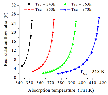
Figure 3 shows that absorption cycle different temperatures are strongly related. In this case, it would be important to know the useful range of absorption temperatures Tu1 that can be achieved according to the low potential source temperature (at solar collector) ranging from 323 K to 373 K.
Figure 3. The variation of recirculation flow ratio according to absorption temperature for Tc =318 K at the inlet of the condenser
In order to determine the range of absorption temperatures, it would be necessary to determine the circulating solution specific flow rate variation range (recirculation flow ratio), which corresponds to two degassing ranges (ΔXab=Xr-Xp) for two condensation temperature values (298 K and 318 K respectively). A large degassing range of 0.2 (20%) is associated with a low recirculation flow ratio (F=2), while the small degassing range of 0.02 (2%) is related to a high recirculation flow ratio (F=24).
It can also be seen that the useful absorption temperature corresponding to a recirculation flow ratio F=24 is only slightly different, or even tends to zero, from that corresponding to a recirculation flow ratio greater than 24 corresponding to a very small degassing range (ΔX). Thus, the value of F=24 can be considered as operating limit of the studied absorption heat transformer cycle. So, this parameter has an influence on the design of this machine. Its growth leads to an increase in the pump absorbed power (see energy balances) and therefore the decrease in performance. As a result, an average recirculation flow ratio value equal to 12 (F=12) is adopted. This corresponds to a degassing range equal to 0.05 (5%).
Table 2 represents the maximal absorption temperature (Tu1) available according to the heat source temperature (TSC), recirculation flow ratio (F) and the condensation temperatures. It appears that absorption temperature is gradually increasing with the heat source temperature increase (TSC) for the different values of the recirculation flow ratio (F) and the various condensation temperatures fixed between 288 and 318 K.
Furthermore, Table 2 allows finding the absorption useful temperature corresponding to the given values of recirculation flow ratio and supply temperature. It can be noted for each condensation temperature ranging between 298 and 318 K that the maximal value of useful temperature Tu1 (max) ranges between 360 to 401 K and 411 to 472 K respectively, meanwhile the minimal value is equal to 330 K which corresponds to TSC. This can be explained by the decrease of the degassing range (ΔX) already very low for F=24, that would make the cycle physically impossible. A real machine would stop working before that. This justifies the choice of F=12.
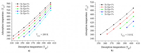
As shown in figure 4, it is possible to reach high adsorption temperatures when the external medium or the condenser temperatures are much lower. It also appears that the condensation temperature has an influence on the hot source temperature (Tu1). It limits the range of variation of the hot source temperature, that is to say that for each condensation temperature exists a limit or extreme hot source temperature restricting the cycle operation.
Adsorption cycle temperature variations Tads according to the hot source temperature for several working pairs and two concentrations are reported in Table 3 a) and b). Their influence on the behavior of the adsorber is decisive and is directly related to the performance of the considered machine.
Thus, it is also found that increase in hot source temperature (desorption temperature) induces an increase in adsorption temperature on the one hand. On the other hand, an increase in concentration causes a decrease in adsorber temperature for all proposed adsorbents.
The analysis of the obtained results shows also that the zeolite-water pair is the most favorable candidate in this case. For low water concentrations (X=0.1), the zeolite-water pair allowed to obtain relatively high temperatures in the order of 575 K with desorption temperatures ranging from 373 to 383K. While the couple silica gel-water allowed to reach adsorption temperatures in order of 493K. These temperatures are above 473K for activated carbon and activated carbon fiber for desorption temperatures around 373K and an adsorbate concentration equal to X=0.1.
Table 2. Absorption temperature variation (Tu1) according to supply (TSC) and condensation (TC1) temperatures for several recirculation flow ratio F
|
T C1= 298 K |
T C1= 318 K |
|||||||
|
Heat source temperature TSC |
2 |
6 |
14 |
24 |
2 |
6 |
14 |
24 |
|
323 |
324.2 |
338.2 |
345.2 |
347.9 |
-- |
-- |
-- |
-- |
|
327 |
329.8 |
345.6 |
353.4 |
356.3 |
-- |
-- |
-- |
-- |
|
331 |
335.6 |
353.0 |
361.6 |
364.9 |
-- |
-- |
-- |
332.0 |
|
335 |
341.5 |
360.6 |
370.0 |
373.5 |
-- |
-- |
338.6 |
340.2 |
|
339 |
347.6 |
368.3 |
378.5 |
382.4 |
-- |
341.7 |
346.7 |
348.5 |
|
343 |
353.8 |
376.1 |
387.2 |
391.5 |
-- |
349.2 |
354.8 |
356.8 |
|
347 |
360.1 |
384.1 |
396.2 |
400.9 |
-- |
356.7 |
362.9 |
365.2 |
|
351 |
-- |
-- |
-- |
-- |
-- |
364.2 |
371.1 |
373.6 |
|
355 |
-- |
-- |
-- |
-- |
-- |
371,7 |
379,2 |
381,9 |
|
359 |
-- |
-- |
-- |
-- |
360.3 |
379.3 |
387.3 |
390.3 |
|
363 |
-- |
-- |
-- |
-- |
366.7 |
386.8 |
395.5 |
398.8 |
|
367 |
|
|
|
|
373.0 |
394.3 |
403.7 |
407.3 |
|
371 |
|
|
|
|
379.4 |
401.8 |
412.1 |
416.0 |
|
375 |
|
|
|
|
385.8 |
409.4 |
420.5 |
424.8 |
|
379 |
-- |
-- |
-- |
-- |
392.1 |
417.0 |
429.0 |
433.8 |
|
383 |
-- |
-- |
-- |
-- |
398.5 |
424.6 |
437.7 |
443.0 |
|
387 |
-- |
-- |
-- |
-- |
404.8 |
432.4 |
446.6 |
452.4 |
|
391 |
-- |
-- |
-- |
-- |
411.1 |
440.2 |
455.8 |
472.1 |
|
a) Adsorption temperature at X= 0.1 |
b) Adsorption temperature at X= 0.3 |
|||||||
|
Generator temperature |
Zeolite 13x /water |
Gel /water |
Activated carbone /methanol |
Activated carbone fiber / Methanol |
Zeolite 13x /water |
Gel /water |
Activated carbone/ methanol |
Activated carbone fiber /methanol |
|
363 |
544.9 |
466.9 |
447.6 |
458.0 |
377.1 |
393.3 |
398.3 |
411.9 |
|
368 |
552.4 |
473.3 |
453.7 |
464.3 |
382.3 |
398.7 |
403.8 |
417.5 |
|
373 |
559.9 |
479.7 |
459.9 |
470.6 |
387.5 |
404.1 |
409.3 |
423.2 |
|
378 |
567.5 |
486.2 |
466.0 |
476.9 |
392.7 |
409.5 |
414.7 |
428.9 |
|
383 |
575.0 |
492.6 |
472.2 |
483.2 |
397.9 |
415.0 |
420.2 |
434.5 |
|
388 |
582.5 |
499.0 |
478.4 |
489.5 |
403.1 |
420.4 |
425.7 |
440.2 |
|
393 |
590.0 |
505.5 |
484.5 |
495.8 |
408.3 |
425.8 |
431.2 |
445.9 |
|
398 |
597.5 |
511.9 |
490.7 |
502.1 |
413.5 |
431.2 |
436.7 |
451.6 |
|
403 |
605.0 |
518.3 |
496.9 |
508.4 |
418.7 |
436.6 |
442.2 |
457.2 |
A preselection study of ambient air and helium (He) as monophasic fluids for the converting device in the first power plant configuration was carried out on the basis of an early study exposed in [20]. This study revealed that for higher isentropic compression and expansion efficiencies (ηis,D=ηis,C=0.9), the Brayton machine operating with the helium as working fluids is operational only from values greater than 493K. For hot source temperature values greater than 493K, the Joule cycle operating with helium shows low efficiency compared to that operating with atmospheric air, which allows dropping the helium from working fluids list under these conditions.
From Table 3, the adsorption temperature (Tads) variation range is much greater for the zeolite 13X-water pair. It reaches the maximum value of 575 K at the feed source temperature ranging in from 373 to 383 K. The adsorption temperature depends on the other operating temperatures of the cycle, so it is difficult to set it, since it has the most important effect on the sorption heat transformation performance and the behavior of the machine. Its influence on the evaporator behavior can be verified by the Dubinin-Astakhov model which expresses the dependence of the adsorbed mass corresponding to this temperature (Tads) and the saturation pressure at the temperature of evaporation m=f (Tads, PS (Te)).
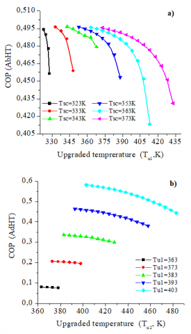
Figures 5 a and b show that both heat transformers efficiencies are decreasing with the increase of the upgraded temperature. Its maximal value is of the order of 0.49 for the absorption cycle. It should be noted that the ranges of the upgraded temperature move upward when solar collector temperature increases. Even more, those ranges are widening. However, efficiencies ranges remain almost unchanged.
Moreover, the adsorption cycle efficiency as shown in Figure 5 b reaches a higher maximal value with respect to the absorption cycle equal to 0.58, which corresponds to the generator maximal feeding temperature Tu1 = 403 K. This efficiency is decreasing with the increase of the upgraded temperature Tu2. Nevertheless, it should be noted that efficiencies ranges move more and more upwards with the increase of the generator heating temperature. That is to say, for an upgraded temperature Tu1 = to 363 K, the upgraded heat sink temperature ranges from 363 to 378 K which corresponds to an almost constant COP of the order of 0.07. The maximal upgraded heat sink temperature reaches 483 k for the heat adsorption transformer with a COP equal to 0.44.
Figure 5. Variation of the COP according to the produced useful (Tu) and the solar collector (TSC) temperatures in the a) absorption heat transformer and b) adsorption heat transformer
Table 4. Overall efficiency in the first power plant configuration (with the Joule cycle) according to the heat source temperature (TSC)
|
Heat source temperature (TSC) |
Overall efficiency of the first configuration |
|
357.9 |
- |
|
359.4 |
0.004 |
|
361.0 |
0.012 |
|
362.6 |
0.021 |
|
364.2 |
0.030 |
|
365.8 |
0.039 |
|
367.3 |
0.050 |
|
368.9 |
0.061 |
|
370.5 |
0.072 |
The overall efficiency variation of the first power plant configuration (PPC) with the Joule cycle is shown in Table 4. It follows that the maximal efficiency equal to 0.05 corresponds to the solar collector maximal temperature adopted equal to TSC=368 K. Moreover, below TSC=358 K the power plant is not operational, which corresponds to a higher evaporation temperature equal to 442 K. This means that it would be impossible to produce mechanical work under the chosen conditions. However, the specific mechanical work produced by the power plant is equal to 5.25 kJ / kg and 11.32 kJ / kg for a hot source temperature (TSC) equal to 363 and 368 K respectively.
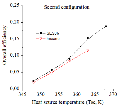
Under the same operating conditions, the Organic Rankine cycle has the best performance with the two fluids proposed with a small preponderance for the SES36 fluid (Figure 6). Moreover, for the ORC cycle operating temperature range, the study revealed that it would be possible to produce mechanical work over the entire range of the proposed temperature.
Figure 6. Variation of the overall efficiency in the second power plant configuration (with ORC) according to the heat source temperature (TSC)
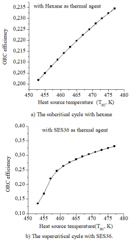
The result of the preselection study shown in figure 7 clarifies the effect of the hot source temperature (Tu2) on the thermal efficiency of subcritical organic Rankine cycle. For this cycle, the thermal efficiency is proportional to the hot source temperature. This observation is identical to that of the supercritical cycle where the maximum values of the thermal efficiency are reached in case of SES36.
The study revealed for the ORC cycle operating temperature range, that it would be possible to produce mechanical work over the entire range of the proposed temperature. Nevertheless, coupling the thermal cascade with the standard cycle (ORC) using hexane as the working fluid will produce more mechanical work compared to the supercritical cycle operating with the SES36.
Figure 7. The variation of the thermal efficiency of the ORC according to the hot source temperature
Figure 8. Variation of the electrical powers according to the solar collector temperature in the 2nd power plant configuration (with ORC) in case of two working fluids
The same figure shows that, within the considered hypotheses, the second power plant configuration allows to satisfy electricity requirements in the envisaged power range (10 kWe) at a solar collector temperature equal to 358 K and 363 K in case of subcritical and supercritical ORC respectively.
For the first time, two power plants configurations composed of sorption heat transformers thermal cascades are proposed in this work for power generation from low potential source of solar origin. The study allowed to underline the influence of different power plant component temperatures on its performances and to identify the key parameters for its optimization. The analysis showed that growth of the low potential source temperature (solar collector), is accompanied by the growth of the absorber and the adsorber temperatures, Joule cycle and ORC efficiencies and finally the power plant overall efficiency. This phase has also allowed choosing the working fluid and the best reactive pair.
A mathematical model has been developed according to the various power plant components balances. The modeling revealed that the Joule cycle is not operational for low potential source temperatures below 358 K. The configuration operating with the Joule reciprocating converter remains inefficient to the threshold temperature mentioned above. Its overall efficiency hardly exceeds 5%. However, the second power plant assembly scheme with the organic Rankine conversion machine demonstrated the best performance over the entire proposed solar collector temperature range. The maximal overall conversion efficiency of this second configuration reaches 18%, which is much above photovoltaic conversion systems efficiency.
Despite the remarkable 2nd power plant configuration performance, it is important to point out that the adsorption cycle S/G (solid / gas) operates in a discontinuous manner. In this case the implementation of a storage system is an operating constraint. Finally, it must be emphasized that a technical and economic study is necessary. It will determine the production costs of the kWh.
|
OP |
Coefficient of performance |
|
T |
Temperature, K |
|
Tm |
Average temperature |
|
P |
Pressure, Pa |
|
F |
Recirculation flow ratio |
|
h |
Enthalpy, kJ kg-1 |
|
ṁ |
Mass flux rate, kg S-1 |
|
ORC |
Organic Rankine Cycle |
|
PPC |
Power plant configuration |
|
Q |
Heat rate, kJ S-1 or kW |
|
∆T |
Approach temperature in heat exchangers, °C |
|
Ẇ |
Mechanical work rate, kJ s-1 or kW |
|
∆Xab |
Concentration difference between weak and strong absorbent |
|
Xp |
Absorbent weak concentration |
|
Xr |
Absorbent strong concentration |
|
Greek symbols |
|
|
ε |
Heat exchanger efficiency |
|
η |
First law (or energy) efficiency |
|
μ |
Overall efficiency |
|
∑ |
Total |
|
Subscripts |
|
|
AbHT |
Absorbtion heat transformer |
|
AdHT |
Adsorbtion heat transformer |
|
C1 |
Condenser of the absorption heat transformer |
|
C2 |
Condenser of the adsorption heat transformer |
|
E1 |
Evaporator of the absorption heat transformer |
|
E2 |
Evaporator of the adsorption heat transformer |
|
G1 |
Desorber of the absorption heat transformer |
|
G2 |
Generator of the adsorption heat transformer |
|
HX |
Heat exchanger |
|
in |
Input |
|
is |
Isosteric |
|
PPC |
Power plant configuration |
|
rev |
Reversible |
|
SC |
Solar collector |
|
S1 |
First configuration |
|
S2 |
Second configuration |
|
u and U |
Upgraded |
|
out |
Output |
|
U1 |
Absorber of the absorption heat transformer |
|
U2 |
Absorber of the adsorption heat transformer |
|
Ẇp |
Mechanical pump |
|
1,2,3,… |
State points. |
[1] Zebbar D, Mostefa K, Kherris S, Benzenine H. (2011). Aperçu sur les procédés de la thermo transformation. Modélisation mathématique d’un thermo transformateur à absorption. 3ème Journées d'Études Nationales de Mécaniques, université Hadj Lakhdar de Batna, Algérie.
[2] Zebbar D, Kherris S, Mostefa K, Trari T. (2012). Insight into heat upgrading process. Mathematical modeling of an absorption heat transformer. 8th International Seminar on Systems Mathematical and Physical Modeling, Book of Proceeding, Voronezh, T.3, pp. 117-124.
[3] Zebbar D, Zebbar S, Mostefa K, Kherris S. (2012). Overview of simple and cascading heat transformation processes, mathematical modeling of an absorption heat transformer. 2nd International Days on Renewable Energies and Sustainable Development (2JIERDD), Laghouat, Algeria.
[4] Lee SF, Sherif SA. (2000). Second low analysis of multi-stage lithium bromide/water absorption heat transformers. ASHRAE Transactions 4327.
[5] Rivera W, Cardoso MJ, Romero RJ. (2001). Single-stage and advanced AHT operating with lithium bromide mixtures used to increase solar pond’s temperature. Solar Energy Mater Solar Cells 70(3): 321–330. https://doi. 10.1016/j.applthermaleng.2011.02.040
[6] Shi L, Yin J, Wang X, Zhu MS. (2001). Study on new ejection-absorption heat transformer. Appl Energy 68(2): 161–71. https://doi.org/10.1016/S0306-2619(00)00056-8
[7] Yang S, Qian Y, Wang Y, Yang SY. (2017). A novel cascade absorption heat transformer process using low grade waste heat and its application to coal to synthetic natural gas. Applied Energy 202: 42–52. https://doi.org/10.1016/j.apenergy.2017.04.028
[8] Martínez H, Rivera W. (2009). Energy and exergy analysis of a double absorption heat transformer operating with water/lithium bromide. International Journal of Energy Resources 33(7): 662-674. https://doi.org/10.1002/er.1502
[9] Donnellan P, Byrne E, Oliveira J, Cronin K. (2014). First and second law multidimensional analysis of a triple absorption heat transformer (TAHT). Applied Energy 113: 141-151. https://doi.org/10.1016/j.apenergy.2013.06.049
[10] Ziegler F, Brandl F, VoÈ lkl J, Alefeld G. (1985). A cascading two-stage sorption chiller system consisting of water- zeolite high temperature stage and a water-LiBr low temperature stage. Absorption Heat Pump Congress, Paris.
[11] Stitou D, Spinnera B, Satzgerb P, Ziegler F. (2000). Development and comparison of advanced cascading cycles coupling a solid/gas thermochemical process and a liquid/gas absorption process. Applied Thermal Engineering 20(14): 1237-1269. https://doi.org/10.1016/S1359-4311(99)00053-8
[12] Kanea M, Larraina D, Favrata D, Allanib Y. (2003). Small hybrid solar power systems. Energy 28(14): 1427-1443. https://doi.org/10.1016/S0360-5442(03)00127-0
[13] Mathieu A. (2012). Contribution to the design and thermodynamic optimization of a thermo-electric microcentral. Thesis, EMMA Doctoral School. University of Lorraine.
[14] Tocci L, Pal T, Pesmazoglou I, Franchetti B. (2017). Small Scale Organic Rankine Cycle (ORC): A techno-economic review. Energies 10(4): 1-26. https://doi.10.3390/en10040413
[15] Grenier P, Meunier F, Pons M. (1982). Les différentes possibilités d'application du couple zéolithe 13X-H20 pour le froid solaire en fonction du type de captation de l'energy solaire. I.I.F.-I.I.R.-Commission E1-E2- Jerusalem, p. 20207, (1982/3).
[16] Schuster A, Karellas S, Aumann R. (2010). Efficiency optimization potential in supercritical organic Rankine cycles. Energy 35(2): 1033-1039. https://doi.org/10.1016/j.energy.2009.06.019
[17] Quoilin S, Sébastien D, Tchanche BF, Lemort V. (2011). Thermo-economic optimization of waste heat recovery Organic Rankine Cycles. Applied Thermal Engineering 31(14): 2885-2893. https://doi.org/10.1016/j.applthermaleng.2011.05.014
[18] Castaing-Lasvignottes J. (2001). Aspects thermodynamiques et technico-économiques des systèmes à absorption liquide, Institut Français du froid industriel.
[19] Kherris S, Zebbar D, Makhlouf M. (2014). Contribution à l’optimisation des installations frigorifiques à absorption solaire. Éditions Universitaires Européennes, ISBN: 978-3-8417-8635-7.
[20] Zebbar D, Kherris S, Mostefa S, Horr S, Guettaf M. (2016). Étude théorique du cycle de Brayton irréversible avec régénération d'une centrale thermique à concentration solaire. Revue des Energies Renouvelables 19(2): 199-210.