Tianfan Zhang* | Zhe Li | Zhihao Chen | Xiao Jing
OPEN ACCESS
The multi-agent system (MAS) mainly focuses on group control and network control. The existing studies on the MAS have not clearly defined the system performance, especially network saturation, agent load capacity and data transfer delay. To solve the problem, this paper develops a basic MAS communication framework, and proposes the optimized serial line Internet protocol (O-SLIP). The protocol can be deployed in any agent object and any layer, unifying the communication between the objects in the MAS system, and lays the basis for group control, consistency check, etc. Then, the proposed framework and the O-SLIP were verified through tests on network saturation, agent load capacity and transmission delay. Finally, the author summed up the important issues in the selection and design of MAS communication systems.
multi-agent system (MAS), socket-based connection, optimized serial line Internet protocol (O-SLIP), network saturation, agent load capacity, performance analysis
Recent years has seen extensive research into communication, a fundamental function of the multi-agent system (MAS). However, the existing studies are either limited to the communication of complex protocols like robot operating system (ROS) and ad-hoc network, or failing to create a communication system satisfying the requirements on bandwidth or other properties.
The ROS, as an important achievement of the open design movement, has been widely investigated and modified over the years. For instance, B.G. Morgan [1] integrated robotics techniques like perception, positioning and navigation into the key concepts, tools and models of the ROS. S.S.H. Hajjaj [2] developed a private, secure and direct ROS-to-ROS through port forwarding, eliminating the need for a dedicated middleware, detailed the setting, configuration and troubleshooting of port forwarding for ROS applications, and compared the setting conditions and performance between port forwarding and cloud-based solutions. Z. Obdrazlek [3] created a MAS in the form of a swarm of unmanned aerial vehicles (UAVs), and described the simulation environment and tools for agent communication in the MAS.
The ad-hoc is a special wireless mobile network, in which all nodes have equal status, i.e. there is no central control node. A.I. Alshbatat [4] coupled the decentralized pattern with self-organization, multi-hop routing and dynamic topology. Considering the negative correlation between propagation delay and network throughput of the MAS, Lmai [5] designed a UAV that improves the throughput of linear network in three scenarios using nonzero propagation delays, and confirmed that the normalized throughput, i.e. channel utilization, is below one in most of the available protocols for linear network. T. Yang [6] probed into the global optimal consensus problem for discrete time MASs with bounded control protocols over a fixed and directed communication network. With the aid of stochastic geometry, Thornburg [7] characterized the one-way and two-way (SNR) distributions of a millimeter wave (mmWave) ad hoc network with directional antennas, random blockages, and ALOHA channel access, revealing that mmWave networks have much greater density and spectral efficiency than low-frequency communication networks at certain link distances, despite the presence of blockage, and can improve the load capacity of the MAS. T. Hayet [8] put forward a client/server architecture based on the MAS, aiming to survey sites in a workspace with a set of mobile robots. S.X. Guo [9] set up a point-to-multipoint network that supports multiple robot links and verifies its effectiveness using XBee modules with ZigBee protocol.
Other robotics studies on communication are as follows. M. Rubenstein [10] proposed a low-cost, infrared-based, non-ROS system called the Kilobot, which enables the collective testing of hundreds or thousands of robots, as well as designing, implementing and validating a kilobot collective, where the number of robots is an order of magnitude larger than that of the largest existing robot collective. To mitigate the operator’s visual perception delay over the network, N.Y. Chong [11] introduced an online predictive simulator to the multi-operator-multi-robot (MOMR) teleoperation, performed various tasks in a local area network (LAN) with delays by two slave robots and two operators, and evaluated the performance of the predictive simulator in the MOMR teleoperation. Considering the execution of operator’s command, F. Penizzotto [12] prepared a control plan for delayed bilateral teleoperation of wheeled robots with force feedback, and analyzed the system stability under the dynamic model of the master as well as the remote mobile robot under asymmetric and time-varying delays of the communication channel. H.I. Son [13] suggested assessing the MAS maneuverability by a frequency response function. Focusing on two MASs, Y. Xie [14] presents a bounded local control protocol for each agent, which uses the information acquired from the underlying communication topology and that of its own objective function.
In summary, many algorithms and control methods have been developed for groups (i.e. swarms or collectives) of decentralized cooperating robots, called a swarm or collective. These algorithms are generally meant to control collectives of hundreds or even thousands of robots. However, they are generally validated in simulation only, or on a limited number of robots, for reasons of cost, time, or complexity. The network architecture and its organization are explained in terms of components. What is worse, there is a lack of a widely applicable, protocol-wide communication protocol across the MAS compartment. The performance of the MAS and its communication has not been fully described and discussed, especially under multiple agents. To overcome these problems, this paper designs a communication framework and an optimized serial line Internet protocol (O-SLIP) for the BigPan series MAS system.
The remainder of this paper is organized as follows: Section 2 introduces the basic requirements on the MAS design, reviews the main techniques of wireless communication, and explains the reasons for choosing WiFi; Section 3 designs the basic communication network, highlighting the system architecture, socket-based connection, the O-SLIP, as well as message encapsulation and parsing; Section 4 sets up an MAS communication system and details the two key processes: agent registration-logout and terminal control; Section 5 verifies the performance of the proposed system in terms of network saturation, agent load capacity and data transmission delay; Section 6 wraps up this paper with several conclusions.
This paper mainly considers common low-power wireless communication techniques like Bluetooth and Wi-Fi. This is because low power consumption is conducive to the service life of the system, while the power and frequency bands of wireless communication are restricted by national laws and regulations. General civil license requires that the power consumption of wireless communication system should fall between 100mW and 500mW.
2.1 Basic requirements of the MAS
Three kinds of entities are generally involved in a typical MAS application: the objects to be controlled, a server to provide network support, and agents (humans and/or artificial intelligences) controlling the network and objects. These entities should satisfy the following basic requirements:
(1) The communication between the server and the client (agents) should have low bandwidth and high real-time performance to transmit control commands or data on agent status, and high bandwidth and low real-time performance to transmit images.
(2) The server or sink node should enjoy a large coverage, because the data needs to be analyzed in the local office or a center thousands of kilometers away. The typical coverage for remote management or system status monitoring is 10,000m2, requiring a communication distance between 50m and 100m.
(3) The system should have a sufficiently large load capacity, i.e. support the simultaneous access of the required number of agents and provide them with effective services.
(4) The system should provide on-site or remote terminal accesses, allowing users to control the objects using various devices (even informal devices like Microsoft Xbox controller).
2.2 Typical wireless network techniques
Bluetooth, Wi-Fi, Zigbee, infrared data association (IrDA), dedicated short-range communication (DSRC), long-term evolution-vehicles (LTE-V) and WiMax are the most popular techniques for wireless communication. The latter two techniques are not introduced here, as they are designed for ultra-long-distance communication. The first five techniques were explained and compared below.
(1) The Bluetooth is an open, short-range standard for wireless communication between mobile phones, headsets and handsets. Despite the fast transmission speed, the Bluetooth is constrained by a short transmission distance and protocol incompatibility between different devices [15].
(2) The Wi-Fi is a fast, wireless data transmission technique that covers the distance of several hundred meters and offers easy access to the Internet. This technique has become a necessity in modern life. However, the Wi-Fi is power-consuming and prone to interference, owing to its high communication frequencies [16].
(3) ZigBee is a short-range, low-power wireless communication technology for sensing control applications. It has been widely adopted in the LANs with low requirements on transmission and a close distance. On the upside, ZigBee can support the communication between tens of thousands of nodes; on the downside, the low-power design limits the transmission speed and makes it unsuitable for long-term communication [17].
(4) The IrDa is a point-to-point communication based on infrared technology. The main drawbacks include the easily obstructed line-of-sight transmission, and the proneness to temperature and humidity interferences [18].
(5) The DSRC is an efficient short-range technique for wireless communication between vehicles [19]. The technique is too complex and costly to implement.
The main parameters of the above wireless communication techniques under limited power consumption are presented in Table 1 below.
Table 1. Comparison of major wireless communication technologies
|
Name |
Distance (m) |
Transmission rate (Mb/s) |
Dissipation(mW) |
|
IrDA |
2~10 |
4~16(VFIR) |
100~400 |
|
ZigBee |
10~50 |
≤1 |
20~150 |
|
Bluetooth |
10~50 |
≤1 |
1~100 |
|
Wi-Fi (2.4G) |
10~100 |
~300 |
50~100 |
|
LET-V6 |
~5000 |
~300 |
50~300 |
|
DSRC |
10~100 |
0.5~27 |
50~300 |
The comparison shows that the Wi-Fi enjoys a high transmission rate, a moderate distance and a low power consumption, not to mention its ease of implementation; the Bluetooth consumes only a little power but its transmission rate is too slow to support high load applications in the main network. Therefore, the Wi-Fi was adopted as the access mode of our main communication framework, while the Bluetooth was employed for terminal connection.
Our communication framework was developed based on the analysis on MAS requirements and wireless communication techniques.
3.1 System architecture
Inspired by the MAS model in Reference [20], the author constructed a simplified abstract framework (Figure 1).
Figure 1. System architecture
As shown in Figure 1, the communication framework mainly involves several agent entities, a sever and users. An agent entity refers to a control object or its physical entity/simulator. The server manages the access and communication requests of the agents. Once an agent entity accesses the server, a virtual mapping agent will be created for it, and included to the agent list. The users are typically server administrators or consumers, including AIs. After the user obtains the virtual mapping of an agent entity, a terminal controller (TC) will be created to control the entity.
3.2 Socket-based connection
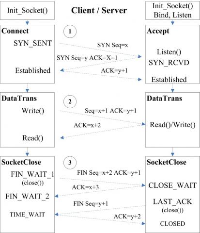
Figure 2 illustrates connection and transmission processes of the basic communication model based on the transmission control protocol and the Internet protocol (TCP-IP) socket. It can be seen that the client and the server communicate in the following steps:
Step 1: The server and client initialize their respective socket object. On the server side, the user should bind the IP address and port number to be exposed, then start monitoring and wait for the client to access the request.
Step 2: The server, using the blocking Accept() method, waits for the user to establish a connection by the Soket.Connect() method. The connection establishment involves the classic three-way handshake process.
Step 3: Both sides can send and receive data separately by Send() and Receive() methods during the establishment of the connection. The Receive() method should be served with a thread to prevent blocking the main program and improve efficiency.
Step 4: The server will end the proxy mapping service for the agent after the connection is closed.
The user object was created because of two reasons: (1) the user is responsible for system configuration and task scheduling for each agent/agent group; (2) the user should monitor the state of each agent and the completion of tasks. Direct agent control is necessary as it is inefficient and unsafe to send the state information to the server without pushing it to all users. There are two application scenarios: (1) the tasks too complex for the AI can be completed remotely by a specific operator; (2) the faulty robot can be controlled by the operator with the terminal access device on site.
Figure 2. Connection and transmission processes
3.3 O-SLIP protocol
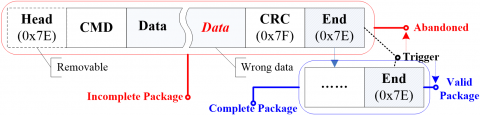
The O-SLIP protocol was developed from the SLIP to accommodate different tasks. This protocol is simple, lightweight, easy to implement and fault-tolerant. The O-SLIP can be used in various positions or layers in the system, such as a microcontroller without an operating system (OS) at the bottom layer, and an embedded AI control platform that may include an OS, provided that the intermediate and terminal PCs are deployable. The underlying tasks are simple but have high real-time requirements and limited hardware conditions. For example, the Nordic nRF905 single-chip transceiver can greatly reduce the complexity of the microcontroller unit (MCU) software by using data ready (DR), but the reduction is limited by the internal cache size of the MCU and the chip. If the cache is only 32B, then the minimum number of valid bytes will be limited to 15B. Meanwhile, the upper-middle tasks are complex but requires low real-time performance (e.g. image processing). Both kinds of tasks can be solved excellently by the O-SLIP protocol. Similar to the SLIP protocol, the package structure of the O-SLIP can be defined as:
$SLI{{P}_{package}}=\left( Header,CMDs,Datas,CRC,End \right)$ (1)
where Header and End are both terminators 0xFF; CMDs is the control command bit; Datas is the data bit. The lengths of the latter two are user-defined. The default verification method is CRC16. Figure 3 shows a complete O-SLIP package.
Figure 3. A complete O-SLIP package
The shortest package is only 3B if CRC8 is used with no data bits and the maximum transmission unit (MTU) can be up to 65kB using CRC16. Compared with the original SLIP, the O-SLIP has the following advantages: (1) the short structure can be adapted to the most cache-constrained system (nRF905); (2) 253 first-level commands and 216 double-byte commands can satisfy all kinds of needs, and Dates can be NULL when the instruction can meet the demand; (3)The variable CMSs and Dates can support different applications within a single protocol, e.g. image transmission and other complex applications can be supported with up to 64kB of valid data bits.
The O-SLIP differs from the general protocol in the following aspects: First, the O-SLIP contains two terminal and cyclic redundancy check (CRC) bits, Head and End. Second, the device address is not indispensable to the data portion of the protocol, and the basic operating mode is the broadcast mode. Third, the count trigger of the general protocol is replaced with the special character trigger, which is compatible with the count trigger mode. Fourth, the rules in the data portion are fully customizable, in addition to the special character transfer rules.
Based on the terminator trigger, the design enjoys two distinct advantages: First, both fixed-length and variable-length formats are supported without needing to know the message length; Second, the system-level errors arising from truncation and misalignment in data transmission can be fully avoided. If a problem occurs, the current invalid datagram will be discarded when the most recent terminal is encountered. The datagram will be reinitiated from the next message, thus acquiring strong fault tolerance. Note that both Head and End, as 0x7E terminators, will be triggered invalidly in this case; in actual use, the Head is generally removed. The testing results show that system stability will not change greatly under high load.
3.4 Message encapsulation and parsing
The O-SLIP contains two abstract functions: message encapsulation and parsing. The users can implement and optimize the two functions according to the language they use. The process of encapsulation is shown as Algorithm 1 below.
|
Algorithm 1 Pseudo code of message encapsulation. |
|
Input: The CMDs and/or Datas are unified into $Data_{Input}\{d_1,d_2,⋯,d_m \}$ for simplification. Output: The encapsulated, directly transmittable data result $Data_{output}$ 1: int Index_O=0 // set length and index in conversion 2: DO[Index_O++]="0xFF" //starting character 3: for each i∈[0,m-1] do // traversing the input data set. 4: if $d_i$=="0xFF" then // is equal to terminator character 5: DO[Index_O++]="0x7C" 6: else if $d_i$=="0x7C" then // is equal to escape character 7: DO[Index_O++]="0x7C" 8: DO[Index_O++]="0x7C" 9: else 10: DO[Index_O++]=d_i 11: end if 12: end for 13: Calcu_CRC(*DO,1,Index_O-1) 14: DO[Index_O++]="0xFF" // end character 15: return DO and Index_O |
Note whether the input data is included in the terminator and the escape character needs to be converted separately. The MTU was limited to 32kB to control character escaping in extreme cases. The process of message parsing is shown as Algorithm 2 below.
|
Algorithm 2 Pseudo code of message parsing. |
|
Input: Received $Data_{Rec}\{dr_1,dr_2,⋯,dr_n\}$, denoted as DR. Output: The result $Data_{User}$ , denoted as DU , may include both CMDs and Datas, depending on the needs of the user int Index_R=0,Index_U=0 2: bool is Escape="false" // mark of escape character for each j∈[0,n-1] do 4: if $d_j$=="0xFF" then // CRC16 default and minimum length is 3 6: if buff≠"NULL" and buff.len≥3 then isVeri=Calcu_CRC(*buff,0,Index_U) 8: if isVeri=="true" then return DU and Index_U 10: else// there is no verified data Index_U"=0" , continue 12: end if end if 14: else if $d_j$=="0x7C" then // escape character if isEscape=="false" then 16: DU[Index_U++]="0xFF" , isEscape="true" else 18: DU[Index_U-1]="0x7C" , isEscape="false" end if 20: else//general data DU[Index_U"++" ]=DR[j] , isEscape="false" 22: end if end for |
Data parsing is the reverse process of encapsulation. The main difference between the two processes lies in the acceptance timing and fault toleration. Loop triggering was adopted (3~12) at data reception due to the possible packet truncation. Besides, the validity of the data n the DU should be determined whenever a terminator 0xFF is read. If valid, the data should be returned to the caller.
Registration, logout and terminal control are the three main functional modules in the MAS. Among them, registration and logout are responsible for access management of the MAS, while terminal control provides two basic methods for the users to control the system.
4.1 Registration and logout
With similar processes, registration and logout were merged into one module (Figure 4).
The registration is realized in seven steps. First, the client and the server establish a connection through socket and the O-SLIP; if the client succeeds in connection, the MAS_UI sends a registration notification to the Agent Manager; then, the Agent Manager creates the agent proxy object, and adds the authenticated object to the Agent List, such that the agent entity can be managed and served by the agent; after being created and activated, the agent entity will receive a verification confirmation message from the agent; when the entity verifies the message, it will reply the status is “online”; then, the agent will notify the Agent Manager to update the entity status; finally the UI will be updated.
Figure 4. Registration and logout module
The logout process is basically the same as the registration process. The only difference lies in the last two steps. Logout was divided into normal and abnormal situations. For normal logout, the agent entity should send a request (the server may also demand the entity to logout); abnormal logout may occur when the network fails and should be treated in two ways: (1) Socket Exception will be detected at network failure, triggering the logout; the daemon thread in Agent Manager periodically requests all agents in the Agent List to confirm their statuses, and the offline agents will be removed.
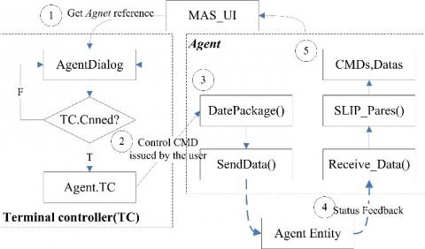
4.2 Terminal control
MAS applications generally demand the single and group controls of agent entities. The group control can be realized based on Agent Manager and Agent List, but the process and algorithm vary from system to system. Thus, the implementation process is not discussed at length here. Instead, the process of user’s direct terminal control over a single agent entity was explained in details (Figure 5).
Figure 5. Process of terminal control over a single agent entity
To directly control a single agent entity, the user should send a request to the server. Then, the TC will be created in the MAS_UI, making the user an administrator or authorizing him/her the control power. The TC will obtain the access permission of the current agent, including the socket connection object. The manual control command will be entrusted to the agent by the TC and sent to the entity. The status feedback by the entity will still be sent to the Agent instead of the TC, and sent to TC after data parsing. This process requires no understanding of the details on the internal implementation, thus reducing the difficulty in user customization.
Multiple TC objects can be created by colleagues in administrator mode, but only one of them can be directly controlled at a time (the group control function should be called to control all these objects at the same time). In addition, the TC may be controlled by humans or AIs. To realize single or group control, the user only needs to request for a proper number of TCs.
This section verifies the performance of our MAS communication framework in terms of network saturation, agent load capacity and data transmission delay.
5.1 Test environment and key parameters
To simulate the MAS network environment, a PC (Intel® Core™ i7-7700K Processor @4.2GHz,16 GB DDR4 memory) was selected to act as the server, two agent simulators were deployed separately in laptops (Intel® Core™ i7-4700MQ Processor @2.4GHz, 8GB DDR4 RAM, 150Mbps TP-Link TL-WN726N WiFi Wireless USB Adapter) to simulate the agents, while a WiFi router (300Mbps TP-Link TL-WDR5620 @ 2.4G, 802.11AC) was employed to simulate the connection between the sever and the agents. The proposed framework and protocol were implemented based on .NET 4.0.
The key test parameters were configured as network speed $NS_{MAX}$ =150Mbps at 2.4GHz, package length $PL_s$=38B and send cycle $PT$=10ms. The test framework is illustrated in Figure 6 below.
Figure 6. The test framework
Each simulator was controlled by a management thread called Agent Manager, and each cycle $T_{creat}$ attempted to create and initialize an agent object and add it to the Agent List $Agents=(Agent_1,Agent_2,⋯,Agent_n)$. The network traffic (NT) generated by these agents can be expressed as:
$NT=\sum\nolimits_{1}^{n}{{P{{L}_{i}}}/{P{{T}_{i}}}\;}\quad \left( Bytes/s \right)$ (2)
If the message length and transmission cycle are constant, equation (2) can be rewritten as $n×\frac{PL}{PT}$ . The network saturation NB can be defined as:
$NB=(NT/NS_{MAX})\times 100$ (%) (3)
The number of agents can be calculated when the network reaches saturation:
$Agent{{s}_{count,NB}}=\operatorname{int}\left( {N{{S}_{MAS}}\times PT}/{PL}\; \right)$ (4)
5.2 System tests
Three sets of tests, each of which lasted 200min, were performed in the above environment, respectively concerning network saturation, agent load capability and data transmission delay. The results on the three test sets are shown in Figures 7~9, respectively. In each test, over 9.5 million records were saved on the server side in the basic format: "[IP]: [PortNo]-[SendTime]-[ReceivedTime]-[AgentCount]". The records were divided into two groups: "LogMag.Log" and "Receive*.log". The test time was measured in the unit of “ticks” or nanoseconds, which is supported by the OS. Then, the mean transmission delay in the test period was determined under the current conditions of at least 5s. Due to the shear amount of data, the aggregated log records were processed in MS SQL Server before the statistical analysis.
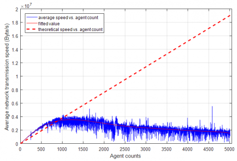
Figure 7. Network saturation vs. the number of agents
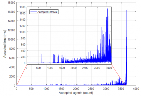
Figure 8. Acceptance time vs. the number of accepted agents
As shown in Figure 7, the actual transmission speed averaged at about 90Mbps and the number of agent $Agents_{count,NB}≈2960$. The speed was attenuated by computers, routers and the environment, failing to reach the theoretical value of 150Mbps. Obviously, the $Agents_{count,NB}$ did not appear as scheduled. The actual bandwidth was basically equivalent to the theoretical value when the number of agents was fewer than 1,000, and gradually decreased after the number surpassed 1,000. Even if the number of agents eventually reached 5,000, there was no frequently disconnection, an evidence of the system stability.
As shown in Figure 8, the server and routers were under tremendous pressure as the number of agents continued to grow. With the increase in data transmission demand, it was increasingly unstable and time-consuming for new agents to access the network.
When the $Agents_{count} \in[1,3100]$ , the access response was generally stable; when the $Agents_{count} \in 3100,3650$ , there was a certain degree of oscillation in the access response; when the $Agents_{count}>3650$ , the response delay increased dramatically to unacceptable levels. Therefore, the agent load of the system was saturated at $Agents_{count,NB}'≈3650$. This explains why the network failed to reach the theoretical limit and saturated under the growing number of agents. After all, lots of time and bandwidth were wasted by excessive service requests.
Figure 9. Mean transmission delay vs. the number of agents
It can be seen from Figure 9 that network saturation increased the data transmission delay. The mean transmission delay was evaluated by a curve with 95% of fitness, revealing that the transmission delay increased to 500ms when the number of agents reached 130. This delay is unacceptable for general applications like the out-of-sequence measurement (OOSM) [20]. In addition, the delay surpassed 5,000ms when the agent count reached 220, and surged up to 105 ms level when the latter was 380, which is unacceptable for general control.
In the system tests, the actual network load, the number of agents, and the transmission delay all deviated far away from the theoretical values, which were not discovered in previous studies. Hence, our research reveals two important issues in the selection or design of MAS network systems:
(1) Data transmission delay is the primary factor to consider in addition to control demand. Despite its proportional relationship to the number of agents, the delay will not grow linearly under ideal conditions, even if the total bandwidth is lacking. The proper delay and agent count can be determined through simple tests or cited from this paper, e.g. the agent count within 130 is acceptable for a delay of 500ms.
(2) The system’s bandwidth redundancy decreases with the growth in the number of agents. Hence, the number of agents should be controlled to release more bandwidth for additional operations. Special attention should also be paid to the access timing of the agents. Numerous concurrent acess requests will drag down the performance of the system in a short time even if there seems to be enough resources.
This paper designs a communication framework, highlighting the system architecture, socket-based connection, the O-SLIP, as well as message encapsulation and parsing, and proposes an optimized serial line Internet protocol (O-SLIP) for the MAS system. The protocol can be deployed in any agent object and any layer, unifying the communication between the objects in the MAS system, and lays the basis for group control, consistency check, etc. After that, the author verified the performance of the proposed system in terms of network saturation, agent load capacity and data transmission delay. Finally, the author summed up the important issues in the selection and design of MAS communication systems.
This research was partially supported by Hubei Provincial Natural Science Foundation (2018CFB314). Hubei Provincial Department of Education (B2017505). Science and Technology Commission of Shanghai Municipality (16391902702).
[1] Quigley M, Gerkey B, Smart WD. (2015). Programming robots with ROS: A practical introduction to the robot operating system. Rotobs and Computer, 170-172. http://doi.org/10.1017/CBO9781107415324.004
[2] Hajjaj SSH, Sahari KSM. (2017). Establishing remote networks for ROS applications via port forwarding: A detailed tutorial. Inter- national Journal of Advanced Robotic Systems 14(3): 172988141770335.
[3] Obdrzalek Z. (2016). Software environment for simulation of UAV multi-agent system. International Conference on Methods and Models in Automation and Robotics, 720-725. http://doi.org/10.1109/MMAR.2016.7575225
[4] Alshbatat AI, Liang D. (2010). Cross layer design for mobile Ad-Hoc unmanned aerial vehicle communication networks. International Conference on Networking Sensing and Control, 331-336. http://doi.org/10.1109/ICNSC.2010.5461502
[5] Lmai S, Chitre M, Laot C, Houcke S. (2017). Throughput-efficient super-TDMA mac transmission schedules in ad hoc linear underwater acoustic networks. IEEE Journal of Oceanic Engineering 42(1): 156-174. http://doi.org/10.1109/JOE.2016.2537659
[6] Yang T, Wan Y, Wang H, Lin Z. (2018). Global optimal consensus for discrete-time multi-agent systems with bounded controls. Automatica 97: 182-185. http://doi.org/10.1016/j.sysconle.2017.02.002
[7] Bai TT, Heath RW. (2016). Performance analysis of outdoor mmWave ad hoc networks. IEEE Transactions on Signal Processing 64(15): 4065-4079. http://doi.org/10.1109/TSP.2016.2551690
[8] Hayet T, Knani J. (2016). A navigation model for a multi-robot system based on Client/Server model. International Conference on Control Decision and Information Technologies, pp. 644-648. http://doi.org/10.1109/CoDIT.2016.7593638
[9] Guo SX, Li X, Guo J. (2016). Study on a multi-robot cooperative wireless communication control system for the spherical amphibious robot. International Conference on Mechatronics and Automation, pp. 1143-1148. http://doi.org/10.1109/ICMA.2016.7558723
[10] Rubenstein M, Ahler C, Nagpal R. (2012). Kilobot: A low cost scalable robot system for collective behaviors. International Conference on Robotics and Automation, pp. 3293-3298. http://doi.org/10.1109/ICRA.2012.6224638
[11] Chong NY, Kotoku T, Ohba K. (2000). Use of coordinated online graphics simulator in collaborative multi-robot teleoperation with time delay. Robot and Human Interactive Communication, 167-172. http://doi.org/10.1109/ROMAN.2000.892489
[12] Penizzotto F, Garcia S, Slawinski E, Mut V. (2015). Delayed bilateral teleoperation of wheeled robots including a command metric. Mathematical Problems in Engineering, 1-13. http://dx.doi.org/10.1155/2015/460476
[13] Son HI, Chuang LL, Franchi A, Kim J, Lee DJ, Lee S, Bülthoff HH, Giordano PR. (2011). Measuring an operator's maneuverability performance in the haptic teleoperation of multiple robots. Intelligent Robots and Systems, 3039-3046. http://doi.org/10.1109/IROS.2011.6094618
[14] Xie YJ, Lin ZL. (2017). Global optimal consensus for multi-agent systems with bounded controls. Systems and Control Letters 102: 104-111. http://doi.org/10.1016/j.sysconle.2017.02.002
[15] Khan LU. (2017). Visible light communication: Applications, architecture, standardization and research challenges. Digital Communications and Networks 3(2): 78-88. http://doi.org/10.1016/j.dcan.2016.07.004
[16] Yiakoumis Y, Bansal M, Covington GA, Van Reijendam J, Katti S, Mckeown N. (2014). Behop a testbed for dense WIFI networks. Workshop on Wireless Network Testbeds Experimental Evaluation and Characterization 18(3): 71-80. http://doi.org/10.1145/2721896.2721912
[17] Khan WM, Zualkernan IA. (018). SensePods: A ZigBee-based tangible smart home interface. IEEE Transactions on Consumer Electronics 64(2): 145-152. http://doi.org/10.1109/TCE.2018.2844729
[18] Biddlestone S, Redmill K, Miucic R, Ozguner U. (2012). An integrated 802.11p wave dsrc and vehicle traffic simulator with experimentally validated urban (los and nlos) propagation models. IEEE Transactions on Intelligent Transportation Systems 13(4): 1792-1802. http://doi.org/10.1109/TITS.2012.2213816
[19] Palattella MR, Dohler M, Grieco A, Rizzo G, Torsner J, Engel T, Ladid L. (2016). Internet of things in the 5g era: Enablers, architecture, and business models. IEEE Journal on Selected Areas in Communications 34(3): 510-527. http://doi.org/10.1109/JSAC.2016.2525418
[20] Li Z, Zhang H, Mu D, Guo L. (2016). Random time delay effect on out-of-sequence measurements. IEEE Access 4: 7509-7518. http://doi.org/10.1109/access.2016.2610098