Talha Irshad | Dahaman Ishak* | Mazhar H. Baloch
OPEN ACCESS
Wireless Power Transfer (WPT) system is an alternative and promising candidate for charging need of many electrical devices and equipment such as electric vehicles, biomedical implants, portable tools, smart phones and network sensors. Most widely used WPT techniques are inductive coupling and magnetic resonance coupling (MRC). In this paper, modeling and analysis of mid-range and mid-power four-resonator coil system for WPT is presented. In the proposed system, comparative analysis of the efficiency and transferred power for different coil structures and topologies such as Two-coil, Three-coil and Four-resonator coil using Keysight ADS tool has been carried out. From the results, the Power Transmission efficiency (PTE) and the transferred power in the proposed four-resonator coil system are 74.670 % and 3.8 W for circular coil structure, and 81.487 % and 4.7 W for rectangular coil structure at 13-cm distance respectively. The findings of this research show that the four-resonator coil system with rectangular structures is the most desirable option for Power and efficiency improvement.
wireless power transfer, mutual inductance, coupling coefficient, power transmission efficiency, circular coil, rectangular coil
Wireless Power Transfer (WPT) system is an alternative and promising candidate for meeting the charging need of many daily life applications e.g. electric vehicles, biomedical implants, personal portable devices, home appliances, network sensors, and machine tools [1]. The motivation for simplying the charging need took researchers to investigate alternative charging technologies. The most promising candidate for this comes out to be Wireless Power Transfer (WPT) technology. In WPT, power is transmitted wirelessly by various methods which will be explained in detail later. Nowadays, a lot of inductive and magnetic resonance based chargers are in market, for example, the wireless charger for Nokia Lumia 92. A new platform has been formed for WPT called Wireless Power Consortium (WPC) and it also has endorsed the first part of International Standard of Wireless Power Transfer-‘Qi’ [2].
Wireless power transfer (WPT) can be classified into two categories namely, far-field wireless power transfer system and near-field wireless power transfer system. A lot of work has been done in different domains of WPT such as associated power electronics circuitry, coils optimization and resonance circuitry. In [3], the authors used a DC-DC converter to transform the load for impedance matching for achieving eventually high efficiency. Similarly, a maximum efficiency point tracking method was analysed and verified in [4] in which the voltage is controlled using feedback control system from the output voltage of the secondary side dc-dc converter to primary side input voltage. Work in [5] focused on coils optimization, for example, a four-coil WPT system was used in which the coil parameters were optimized for the self-inductance (L), mutual inductance (M), resistance (R) and capacitance (C).
One of the important parts in the design of Wireless power transfer is the design of wireless link and the efficiency of this part is crucial for WPT system. There are many ways in which the efficiency of the wireless link can be maximized, and one of them is load transformation method. In load transformation method, load resistance is transformed to its optimum value. There are four different load transformation methods which are: DC-DC converters to alter the load impedance, Passive Circuits for impedance matching, variable frequency control and Reconfigurable Resonant circuits for impedance matching [6].
The Coil Optimization in WPT system is very important and crucial factor in enhancing the PTE the system. In coil optimization, the coil parameters such as: Inductance, Capacitance and Quality Factor are optimized. In addition, the Coupling Parameters in WPT system such as Coupling Coefficient and Mutual Inductance also fall into this category. Similarly, many researchers worked on Multi-Coil system. Categorically, there are three main general topologies in WPT system with regard to the number of coils i.e. two coil, three coil and four coil system.
However, in this paper, the objective is to present the comparative analysis of the power transfer efficiency (PTE) of rectangular and circular coil structures. The four-coil WPT system with 2nd and 3rd coil acting as an intermediate resonator is used. For this purpose, mutual inductance is calculated analytically and later used in ADS simulation to evaluate the PTE and transferred power. The following input parameters are used for the transient simulation.
Input voltage Vrms 14 V
Input Current Irms 550 mA
Input Power 7.95 W
The remainder of this paper is organized as follows: Section 2 explains the research methods and technique used in the research work, Section 3 presents the obtained results and these results are evaluated and at last the whole paper is concluded.
A typical Magnetic Resonance Coupling WPT system’s block diagram [7] is shown in Figure 1. It has mainly two parts: First part consists of transmission coils and LC tank on both sides of the wireless link, second part consists of conversion circuits like DC-DC converters, inverter and rectifiers.
Its working principle is quite straightforward. First, an AC supply from the main source is fed to the rectifier and DC-DC converter, which gives the desired DC voltage. After that, a high-frequency inverter is employed to supply the voltage to LC resonator and transmission coils. At the receiver side, it is then rectified to feed the load.
Figure 1. Block diagram for magnetic resonance coupling wireless power transfer system
The equivalent circuit of the four-coil WPT system [8] with intermediate boosters of transmitter and receiver is shown in Figure 2. Mututal inductances between the coils e.g. M23 between 2nd and the 3rd coil are also shown. In the four resonator-coil system, the cross-couplings between the non-neighbouring coils e.g. M14 cannot be ignored as in the conventional four-coil system where couplings between the non-neighbouring coils are very weak.
Figure 2. Four-coil WPT with 2nd and 3rd coils as the intermediate resonator coils
To calculate the maximum power transfer efficiency in ADS software, the parameter S21 is used. However, other important parameters for the four-coil WPT system such as inductance, mutual inductance, coupling coefficient (k) and quality factor (Q) should be analytically calculated.
2.1 Mutual inductance
Mutual inductance for the circular coil is given by
$M_{ij}=\frac{2μ_oN_iN_j\sqrt{a+b}}{(b)}[(1-\frac{β^2}{2})K(β)-E(β)]$ (1)
where,
$a=+\frac{(ri)^2+(rj)^2+d^2}{(ri)^2(rj)^2}$; $b=\frac{2}{(ri)(rj)}$; $β=\sqrt{\frac{2b}{a+b}}$ (2)
Equation (1) is called Neumann Formula [9]. Where ri is the radius of ith coil and rj is the radius of jth coil, Ni is the number of turns of the ith coil and Nj is the number of turns for jth coil.
In case of rectangular coil structure, the mutual inductance between two identical rectangular loops is separately calculated for each side [10]. For this, the rectangular loop is split into four pieces and the partial mutual inductance between two wires of length l for rectangular coil is calculated as in Equation (3).
$M(l,d,a)=\frac{μ0}{2π}[ln(\frac{l}{d+a})+ln\sqrt{\frac{l}{d+a}^2+1}-\sqrt{1+(\frac{d+a}{l})^2}+\frac{d+a}{l}]$ (3)
where l is the length, d is the separation distance between the coils and a is the radius of the wire. The mutual inductance between the two rectangular loops is calculated by making sum of all the partial mutual inductances as in Equation (4).
$M_{12}=4[M(p+l_2,d_1,a)-M(p,d_1,a)-M(p,d_2,a)+M(p+l_2,d_2,a)]$ (4)
where l2 is the side length of the biggest loop and l1 is the side length of the smallest loop. p is given by
$p=\frac{l_1-l_2}{2}$; $d_1=\sqrt{\frac{l_1}{1}-\frac{l_2}{2}+d^2}$; $d_2=\sqrt{\frac{l_1}{1}+\frac{l_2}{2}+d^2}$ (5)
2.2 Coupling coefficient
Equations (6) and (7) represent the coupling coefficient and the quality factor [11] respectively as given below
$k_{ij}=\frac{M_ij}{\sqrt{L_iL_j}}$ (6)
$Q=\frac{w_oL}{R}$ (7)
Coupling Coefficient is the extent of magnetic coupling b/w the two coils and it represents the ratio of the mutual flux to that of the product of the self-inductances of two coils. While the Quality Factor represents the ratio of the energy stored in the coils to the energy dissipated by the coils.
2.3 Scattering-parameters
S-parameters are useful for obtaining the transmission efficiency of two-port networks like wireless links with a transmitter and receiver as shown in Figure 3. Given below are the four-important S-parameters
Reverse Transmission Efficiency $S_{12}=\frac{b1}{a2}$
Input Reflected Power $S_{11}=\frac{b1}{a1}$
Forward Transmission Efficiency $S_{21}=\frac{b2}{a1}$
Output Reflected Power $S_{22}=\frac{b2}{a2}$
Figure 3. Typical 2-Port Network with scattering parameters
2.4 Resonance frequency
In order to achieve Maximum Power Transfer (MPT), both the transmitter and receiver coils should resonate at the same frequency. For this, the resonant frequency should be equal to the transmitting frequency fo which depends upon the coil inductance L and compensation capacitor C [12] as given by
$f_0=\frac{1}{2π\sqrt{LC}}$ (8)
2.5 Parameter Specifications
Coil parameters are calculated by using the equations (1)-(6) and the coil dimensions are extracted from [13]. The resonant freuency mentioned in the table is for three and four coil system. While two coil system has higher resonant frequency i.e. 140 kHz. Calculated electrical and magnetic parameters are then listed in Table 1.
Table 1. Calculated electrical and magnetic parameters for four-coil WPT system
|
Coils |
Specs |
Values |
Coils |
Specs |
Values |
|
Tx1 |
L1 |
18.3uH |
Rx1 |
L3 |
5.66uH |
|
C1 |
62 nF |
C3 |
132 nF |
||
|
R1 |
50mΩ |
R3 |
30mΩ |
||
|
fo |
120 kHz |
fo |
120 kHz |
||
|
N1 |
4 turns |
N3 |
3 turns |
||
|
Tx2 |
L2 |
18.3uH |
Rx2 |
L4 |
22.6uH |
|
C2 |
62 nF |
C4 |
49 nF |
||
|
R2 |
50mΩ |
R4 |
100mΩ |
||
|
fo |
120 kHz |
fo |
120 kHz |
||
|
N2 |
4 turns |
N4 |
6 turns |
3.1 Four-resonator coil WPT system
The above mentioned equations have been used to calculate the mutual inductances and coupling coefficients for both rectangular and circular coil structures at different gaps. The calculated coil parameters such as of L, C and R are listed in Table 1. Using these parameters, PTE is evaluated using keysight ADS tool. S-parameters of the ADS tool are utilized to evaluate the PTE of the proposed four-resonator coil WPT system. Moreover, Transient Simulation is utilized for the evaluation of current and transferred power in both rectangular and circular coil structures.
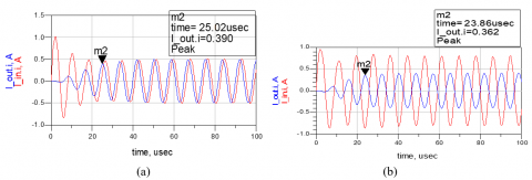
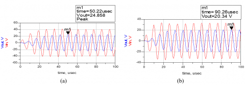
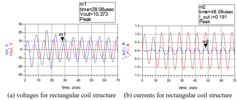
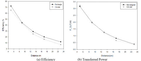
Transient Simulation of the system has been performed in keysight ADS. Output currents and voltages are measured and then plotted in Figures 4 and 5. Figures 6 and 7 shows the efficiency and transferred power for the four-resonator coil WPT system. It is obvious from the figures that rectangular coils have better performance both in Output Power and Efficiency than the circular ones. PTE difference b/w rectangular and circular structures is small at lower transmission distances but it gets higher as the transmission distance increases. For example, both structures have almost same effiency at d=5 cm, while they have large difference at d=23 cm i.e. rectangular=44 % and circular=28 %.
Figure 4. Current waveforms for four-resonator coil WPT system at distance of 13 cm. (a) rectangular coils and (b) circular coil
Figure 5. Output Voltage for four-resonator coil WPT system at distance of 13 cm. (b) rectangular coils and (b) circular coils
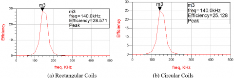
Figure 6. Efficiency for four-resonator Coil WPT at distance of d=13-cm
Figure 7. Efficiency & Output Power for four-resonator coil WPT system for different gaps
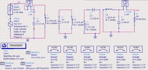
The following schematic in Figure 8 is the four-resonator coil WPT system for the Transient and S-Parameter Simulation in ADS respectively. Figure 8a shows the schematic for Transient Simulation to measure the transferred power in four coil system. Output Power is measured indirectly by measuring the current and voltage at the load side of the 2nd receiver coil. While Figure 8b shows the schematic for the S-parameter Simulation to measure the PTE of the four coil system. This simulation setup is used for the PTE measurement. For PTE enhancement, source and load impedance should match. That’s why the load is kept at optimum value i.e. 50 Ohm.
Figure 8a. Schematic of Four-Resonator-Coil WPT for Transient simulation in ADS
Figure 8b. Schematic of Four-Resonator-Coil WPT for S-parameter simulation in ADS
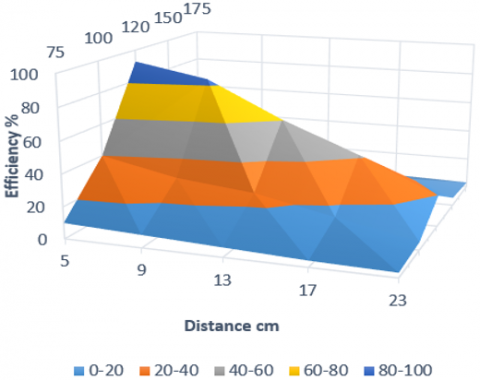
Figure 9. 3D plot of efficiency for four-resonator coil WPT system
In Ahn and Hong [13], the work on four-resonator coil system using rectangular structure was reported. They compared the proposed system with three-coil and conventional four-coil system. However, in this work, four-resonator-coil system is compared with three-coil and conventional four-coil system using both rectangular and circular coil structures. At 13-cm distance, the simulated PTE in ADS tool is 74.670 % for circular coils and 81.487 % for rectangular coils respectively. Similarly, the transferred power for rectangular structure is higher than that of circular coils. The Output Power curve in Figure 7a. is linear for both circular and rectangular structures. The resonance frequency is 120 kHz for both circular and rectangular coils. This frequency is different as compared to the original resonant frequency extracted from equation (6). This is due to the frequency splitting phenomenon.
Figure 9 shows the 3D plot of the efficiency curve vs distance and frequency. As, it can be seen that the efficiency is highest at the resonant frequency i.e. 120 kHz for each distance.
3.2 Three-resonator coil WPT system
For the three-resonator coil WPT system, the output power level is low as compared to our proposed system of four-coil WPT system. Figure 10 shows the voltage and current waveforms. While, Figure 11 shows the efficiency and transferred power for the three-coil system.
Figure 10. Voltages & currents for three-coil WPT System at distance of 13 cm
Figure 10 shows the current and voltage waveforms of three-resonator coil system in ADS. The reason of very small current in three-coil system is the low coupling between the transmitter and receiver as compared to the strong coupling in four-coil system. Figure 11 shows the simulated PTE in kesight at 13-cm distance for both structures. Whereas Figure 12 shows the graphs for PTE and transferred power at different transmission distances. The transferred power and PTE for rectangular coil is higher than circular coil. One important point can be noted in these graphs is that the difference b/w the PTE and Output Power points on the curves of rectangular and circular structures is very small. Moreover, the PTE curves in this case are almost linear for both rectangular and circular structures and have small difference of PTE values b/w these two curves.
Figure 11. Efficiency for Three-Resonator Coil WPT at distance of d=13-cm
Figure 12. Efficiency and output power for three-resonator coil WPT system for different gaps
3.3 Two-coil WPT system
In two-coil WPT system, the transmitting (Tx) and receiving (Rx) coils resonante at 140 kHz for MPT. Frequency splitting as demonstrated in Huang’s study does not occur in the two-coil system due to weak magnetic coupling. That’s why it has very low PTE and Output Power as compred to the 3-coil and 4-coil system. Figures 13 and 14. shows the efficiency and transferred power in two-coil system. It is noted from the graph in Figure 13. that the transferred power is very low i.e. less than 1 Watt. It happens due to the low magnetic coupling in the two-coil system even at small distance. One important difference is the resonace frequency i.e. 140 kHz for 2-coil system which is different from four and three coil system. The reason is the frequency splitting phenomenon which doesn’t happen in 2-coil system. In three and four coil system due to frequency splitting phenomena, resonance frequency splits into two peaks i.e. lower and the higher frequency peaks. The lower frequency is chosen as the resonance frequency.
Figure 13. Power transfer efficiency for the two-coil systems
Figure 14. Output power and efficiency for two-coil WPT system
In this paper, modelling and analysis of mid-range and mid-power four-resonator coil WPT system have been presented. In the proposed work, we have analysed the efficiency and transferred power for different coil structures and topologies. For this purpose, the proposed system was simulated in keysight ADS tool. The efficiency and the transferred power with the proposed four-resonator coil system are 74.670 % and 3.8 W for circular structure, 81.47 % and 4.7 W for rectangular structure at 13 cm gap respectively. The proposed system was compared with three-coil and two-coil systems using both rectangular and circular structures. The two-coil system has shown to yield very low efficiency and transferred power as compared to both three-coil and four-coil systems. While the three-coil system has lower performance than the four-coil system, both in transferred power and also PTE. It is observed in all topologies that the rectangular structure has better performance. In four coil WPT system, the resonance frequency fluctuates due to the strong coupling between the resonators. In order to mitigate this problem, frequency tracking system at the receiver side is desirable.
In the future work, a hardware prototype will be designed for both geometries to measure both PTE and transferred power, and then compare with simulation results for validation purpose.
[1] Wei X, Wang Z, Dai H. (2014). A critical review of wireless power transfer via strongly coupled magnetic resonances. Energies 7(7): 4316-4341. https://doi.org/10.3390/en7074316
[2] Liu N, Wang B. (2014). An LLC-based planar wireless power transfer system for multiple devices. Conf. Proc. - IEEE Appl. Power Electron. Conf. Expo. – APEC, pp. 3411-3417. https://doi.org/10.1109/APEC.2014.6803798
[3] Fu M, Ma C, Zhu X. (2014). A cascaded boost-buck converter for high-efficiency wireless power transfer systems. IEEE Trans. Ind. Informatics 10(3): 1972-1980. https://doi.org/10.1109/TII.2013.2291682
[4] Stone DA, Zhao R, Gladwin DT. (2016). Maximum efficiency point tracking for resonant wireless power transfer. 8th IET Int. Conf. Power Electron. Mach. Drives (PEMD 2016), pp. 5-5. https://doi.org/10.1049/cp.2016.0279
[5] Cheon S, Kim Y, Kang S, Lee ML, Lee J, Zyung T. (2011). Circuit-model-based analysis of a wireless energy-transfer system via coupled magnetic resonances. IEEE Trans. Ind. Electron 58(7): 2906-2914. https://doi.org/10.1109/tie.2010.2072893
[6] Zhong W, Hui SYR. (2017). Reconfigurable wireless power transfer systems with high energy efficiency over wide load range. IEEE Trans. Power Electron 33(1): 6379-6390. https://doi.org/10.1109/TPEL.2017.2748161
[7] Abdelhamid E, Abdelsalam AK, Massoud A, Ahmed S. (2014). An enhanced performance IPT based battery charger for electric vehicles application. IEEE Int. Symp. Ind. Electron 1610-1615. https://doi.org/10.1109/ISIE.2014.6864856
[8] Wang S, Gao D. (2016). Power transfer efficiency analysis of the 4-coil wireless power transfer system based on circuit theory and coupled-mode theory. In 2016 IEEE 11th Conference on Industrial Electronics and Applications (ICIEA) 3(1): 1230-1234. https://doi.org/10.1109/ICIEA.2016.7603772
[9] Nalty K. (2011). Classical calculation for mutual inductance of two coaxial loops in MKS units. Flux Φ and the Vector Potential A 1-8.
[10] Robichaud A, Boudreault M, Deslandes D. (2013). Theoretical analysis of resonant wireless power transmission links composed of electrically small loops. Prog. Electromagn. Res 143: 485-501. https://doi.org/10.1109/NEWCAS.2012.6329042
[11] Kindl V, Kavalir T, Pechanek R, Skala B, Sobra J. (2014). Key construction aspects of resonant wireless low power transfer system. 10th Int. Conf. ELEKTRO 2014 - Proc (5): 303-306. https://doi.org/10.1109/ELEKTRO.2014.6848907
[12] Ahn D, Hong S. (2013). A study on magnetic field repeater in wireless power transfer. IEEE Trans. Ind. Electron 60(1): 360-371. https://doi.org/10.1109/TIE.2012.2188254
[13] Ahn D, Hong S. (2014). A transmitter or a receiver consisting of two strongly coupled resonators for enhanced resonant coupling in wireless power transfer. IEEE Trans. Ind. Electron 61(3): 1193-1203. https://doi.org/10.1109/TIE.2013.2257151
[14] Huang R, Zhang B, Qiu D, Zhang Y. (2014). Frequency splitting phenomena of magnetic resonant coupling wireless power transfer. IEEE Trans. Magn 50(11): 1-4. https://doi.org/10.1109/TMAG.2014.2331143