Ramgopal Reddy Bijjam*![]() | Srinivas Chandanam
| Srinivas Chandanam![]() | Veera Venkata Siva Sudheer Nakka
| Veera Venkata Siva Sudheer Nakka![]() | Sneha H Dhoria
| Sneha H Dhoria![]()
Copyright: ©2023 IIETA. This article is published by IIETA and is licensed under the CC BY 4.0 license (http://creativecommons.org/licenses/by/4.0/)
OPEN ACCESS
Orthotropic rectangular plates, featuring central cutouts and subjected to in-plane loading, are extensively employed across various engineering fields, including mechanical, automobile, aerospace, and marine. The introduction of a cutout inevitably leads to stress concentration within the plate. Incorporating carbon nanotubes (CNTs) into the polymer matrix composite has been noted to induce significant heterogeneity in stress fields. Functioning as bridges between the fibers and the matrix, CNTs can effectively mitigate stress concentration and enhance the damage tolerance of the composite. However, accurately determining stress concentration in CNT-based composites requires comprehensive understanding of the geometric discontinuity edge and well-defined evaluation techniques. Among these, the finite element method emerges as a straightforward yet precise approach for studying stress concentration around geometric discontinuities. The present work harnesses the finite element method to investigate stress concentration in CNT-based multiscale composite plates (Glass Fiber/CNT/Epoxy) with central cutouts under static in-plane loading. To validate the model, the derived results are compared with analytical data from conventional composite materials. Moreover, the impact of cutout size on stress concentration is examined for three distinct configurations: plates with a central circular cutout, plates with an elliptical central cutout (major axis in the longitudinal direction), and plates with an elliptical central cutout (major axis in the transverse direction). Preliminary findings suggest a correlation between increased cutout size and augmented percentage reduction in stress concentration. Notably, the maximum percentage reduction in stress concentration is observed in the case of plates hosting an elliptical cutout at the center with the major axis aligned in the transverse direction.
carbon nanotubes (CNTs), multiscale composites, stress concentration, finite element method
First introduced by Iijima [1], carbon nanotubes (CNTs) have garnered attention due to their remarkable mechanical, thermal, chemical, electrical, and biological properties. The development of CNT-based composites has seen computational methods taking a leading role. The nanoscale presents challenges for analytical modeling and makes experimental tests costly. However, desktop computer simulations have facilitated the modeling of carbon nanocomposites.
While continuum mechanics [2-6] and molecular dynamics [7-10] have been used for modeling and analysis of CNT-reinforced polymer composites, few efforts have been directed towards modeling fiber/CNT/matrix multiscale composites. Orthotropic rectangular plates with central cutouts, loaded in-plane, find wide-ranging applications across mechanical, automobile, aerospace, and marine engineering. Stress concentration, a result of sudden configuration changes under loading, often leads to failure of composite plates due to plastic deformation and fatigue cracking.
Xu et al. [11] employed classical laminated plate theory to explore stress concentration in a composite shell with an elliptical cutout. Khechai et al. [12] studied stress concentration in angle and cross-ply composite laminated plates, and isotropic plates with circular cutouts loaded axially. Sathurusinghe et al. [13] found high stress concentration locations at the junction of the carbon nanotube and matrix at the end-cap. Tzeng and Tsai [14] and Liu and Her [15] further investigated the stress distribution in a single-walled CNT-based polymer composite.
Wang et al. [16] utilized an image-driven finite element modeling method to evaluate stress and strain distribution in CNT/epoxy composites. The simulation results underscored the efficiency of well-dispersed MWCNTs in transferring stresses, thereby reducing localized stress concentration and enhancing deformation resistance in composites. Zeighami and Jafari [17] estimated the stress and moment resultants on the edge of elliptical cutouts in asymmetric FG-CNTRC plates under various loading circumstances using a new analysis based on Lekhnitskiis complex variables method, mapping function, and Laurent series.
While significant research has been conducted to ascertain the stress concentration in nanocomposites (two-phase, including epoxy and CNTs) and conventional composites, there is a noticeable lack of substantial research efforts focusing on the simulation of multiscale composites (three-phase, including fiber, epoxy, and CNTs). In this study, the stress concentration of a CNT-based multiscale composite plate (Glass Fiber/CNT/Epoxy) with a central cutout is examined using the finite element analysis software, ANSYS 17.2. The results are validated by comparing the obtained values with analytical outputs for conventional composite materials.
A composite is one which contains fibres and matrix having entirely distinct properties. It will show uneven response even when it is loaded uniformly. However, the composite is modelled as an orthotropic medium in classical composite theory. The effective moduli of these composites show the average material properties of the composites. In the homogenization technique, a representative volume element (RVE) is taken which is shown in Figure 1 by considering that the embedded material is in a periodic arrangement, and it is assumed that the mean properties of a representative volume element are identical to the mean mechanical properties of the composite.
Figure 1. Periodic microstructures and an RVE
The mean stresses and strains in a representative volume element are calculated using Eqs. (1) and (2):
$\bar{\sigma}_{k l}=\frac{1}{V} \int_V^{\mathrm{}} \sigma_{k l} d V$ (1)
$\bar{\varepsilon}_{k l}=\frac{1}{V} \int_V^{\mathrm{}} \sigma_{k l} d V$ (2)
where, k and l indicates the composite global coordinate directions. The Eq. (3) shows the overall strain energy (U) of the effective medium in the given volume:
$\mathrm{U}=\frac{1}{2} \bar{\sigma}_{k l} \bar{\varepsilon}_{k l} V$ (3)
Performing numerical analysis by applying appropriate boundary conditions to the Representative Volume Model, the effective elastic properties (Eq. (4)) can be determined by the use of strain energy equation and Hooke’s law:
$E=\frac{2 U}{V \varepsilon^2}$ and $G=\frac{2 U}{V \gamma^2}$ (4)
where, U = overall strain energy; ε = strain in axial direction; γ = strain due to shear.
The resultant properties are calculated by considering a square representative volume element for a SWCNT reinforced in an epoxy matrix, moreover in glass composites, is examined using finite element analysis.
Materials and their properties:
The geometric and mechanical properties of material considered in this analysis are:
Single walled carbon nanotubes embedded in a matrix:
Single Walled Carbon Nanotube (SWCNT):
The type of SWCNT is taken in the analysis is armchair (9, 9) considered from the literature [18]
Length Lcnt = 50 nm;
Outside radius rcnt = 0.61 nm;
CNT Effective thickness tcnt = 0.43 nm;
Modulus of Elasticity Ecnt = 1050 nN/nm2;
Poisson’s ratio νcnt = 0.35.
Epoxy Matrix:
RVE side length = variable;
Length of RVE Lm = 120 nm;
Modulus of Elasticity Em = 3.6 nN/nm2;
Poisson’s ratio νm = 0.28.
The resultant properties are obtained by using finite element analysis and the strain energy equations.
Glass/SWCNT embedded in an epoxy matrix:
SWCNT embedded in an epoxy:
Modulus of Elasticity Eem = 5.02 GPa;
Poisson’s Ratio νem = 0.35;
Effective Length Lem = 1050 μm;
Volume Vem = variable;
Length of side = variable.
Glass Reinforcement [19]:
Modulus of Elasticity Ef = 75 GPa;
Poisson’s Ratio νf = 0.2;
Length Lf = 1050 µm;
Diameter df = 20 μm;
Volume fraction Vf = variable.
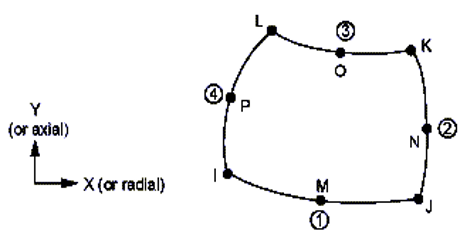
The basic plate configuration for which solutions are given for stress concentrations around cutouts is shown in Figure 2.
Figure 2. Orthotropic plate subjected to axial loading
In case of orthotropic composite plate loaded axially, the tangential stress (σθ) at the edge of the cutout is calculated using the Eq. (5) given by Greszczuk [20]:
$\begin{aligned} & \sigma_\theta=\left[\frac{\left(1+\alpha_1\right)\left(1+\alpha_2\right)\left(1+\alpha_1+\alpha_2-\alpha_1 \alpha_2-2 \cos 2 \theta\right)}{\left(1+\alpha_1^2-2 \alpha_1 \cos 2 \theta\right)\left(1+\alpha_2^2-2 \alpha_2 \cos 2 \theta\right)}\right. \\ & \alpha_1=\left[\frac{\left[\left(\frac{E_T}{2 G_{L T}}-v_{T L}\right)+\sqrt{\left.\left(\frac{E_T}{2 G_{L T}}-v_{T L}\right)^2-\frac{E_T}{E_L}\right]^{\frac{1}{2}}-1}\right.}{\left[\left(\frac{E_T}{2 G_{L T}}-v_{T L}\right)+\sqrt{\left.\left(\frac{E_T}{2 G_{L T}}-v_{T L}\right)^2-\frac{E_T}{E_L}\right]^{\frac{1}{2}}}+1\right.}\right] ; \\ & \alpha_2=\left[\frac{\left[\left(\frac{E_T}{2 G_{L T}}-v_{T L}\right)-\sqrt{\left.\left(\frac{E_T}{2 G_{L T}}-v_{T L}\right)^2-\frac{E_T}{E_L}\right]^{\frac{1}{2}}-1}\right.}{\left[\left(\frac{E_T}{2 G_{L T}}-v_{T L}\right)-\sqrt{\left.\left(\frac{E_T}{2 G_{L T}}-v_{T L}\right)^2-\frac{E_T}{E_L}\right]^{\frac{1}{2}}}+1\right.}\right] . \\ & \end{aligned}$ (5)
where, EL is the longitudinal elastic modulus, ET is the elastic modulus in transverse direction, νTL is the Poisson’s ratio and GLT is the shear modulus.
In this work, the numerical analysis of conventional and multiscale composite plate with central cutout is performed, to study the stress concentration. In the numerical simulation process, PLANE82 element shown in Figure 3 is used. PLANE82 is a 8-noded element, at each node it is having two degrees of freedom. The element can be used as an axi-symmetric element. This is most popular element for the analysis of plates and thin shells often approximated as being under condition of plane stress. It gives more precise results for automatic meshes due to the PLANE82 element has mid-nodes.
Figure 3. PLANE82 element
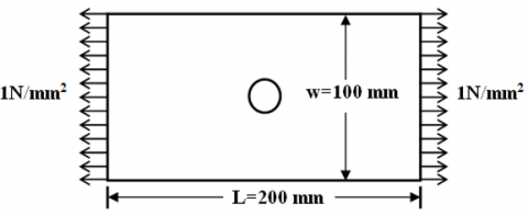
For validation a rectangular plate of 200 mm length, 100 mm width and 1 mm thickness with a circular cutout of 5 mm diameter and uniformly distributed static in plane loading σa=1 N/mm2 as shown in Figure 4 is used.
Figure 4. Rectangular plate with a circular cutout at the centre loaded in a plane
Numerical homogenization is used to find the material properties needed for the analysis of rectangular orthotropic plate which are shown in Table 1.
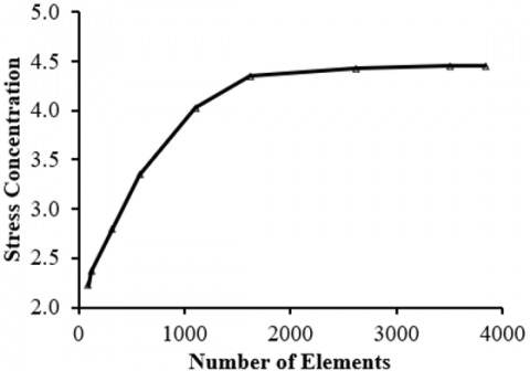
Finite element analysis is performed for stress concentration in a orthotropic rectangular plate with central cutout subjected to inplane loading. Owing to symmetry of the plate, only quarter rectangular plate is analysed. Mapped meshing is used for finite element modelling of quarter plate. A more reliable method of ensuring that the mesh is fine enough is to carry out a convergence study as shown in Figure 5. Using different mesh densities the finite element model of the quarter plate has been developed. The analysis is carried out with ever increasing mesh density till there is no significant difference from one run to another.
Table 1. Elastic properties Glass Fiber/SWCNT/ Epoxy and Glass Fiber/ Epoxy composite at Vf = 60% and Vcnt = 5%)
|
Composite Materil |
EL (GPa) |
ET (GPa) |
GLT (GPa) |
vLT |
Density (kg/m3) |
|
Glass Fibre/SWCNT/Epoxy |
43.5 |
43.5 |
16.02 |
0.28 |
1985 |
|
Glass Fiber/Epoxy |
43.0 |
43.0 |
8.74 |
0.30 |
1980 |
Figure 5. Mesh convergence study for a rectangular plate with central hole
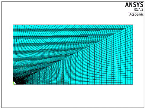
From the Figure 5, it is found that the RVE models with number of elements increasing from 100 to 3500, the stress concentration increases more significantly. The effect of mesh refinement is negligible on the stress concentration, beyond the number of elements 3500. So, the finite element model, which is having 3840 elements and 11777 nodes producing converging results shown in Figure 6 is used for this study.
Figure 6. Meshed model of quarter rectangular plate with circular cutout
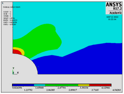
Symmetric boundary conditions are applied on the quarter model to account for the full model. By using finite element method and applying necessary loading and boundry conditions, the tangential stress around the edge of the cutout is obtained. Figure 7 shows stress results obtained by finite element method for an rectangular orthotropic plate with central circular cutout having final optimum mesh.
Figure 7. Stress concentration for an orthotropic rectangular plate with central circular cutout
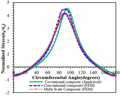
Stress concentration in conventional as well as multiscale composite plate with central circular cutout is determined using numerical analysis. Figure 8 shows the normalized stress as a function of circumferential angle for both conventional and multiscale composites.
The obtained results are compared with the analytical results for a composite plate containing central circular cutout. A good correlation is observed between the two. It can also be noted that the stress concentration is high nearly at 90° circumferential angle and this trend is similar to that of isotropic materials. Further, it is found that the stress concentration is reduced by about 8% due to addition of CNTs to the glass fiber composites.
Figure 8. Variation of normalized stress (σθ/σa) with the circumferential angle
From the in depth observations, it is found that the reduction in stress concentration is due to change in ET/GLT ratio, because the stress concentration is not effected too much by the change in EL/ET ratio.
To investigate the effect of cutout size upon the stress concentration around the edge of a cutout of multiscale composite plate, a rectangular plate of length 200 mm, width 100 mm and thickness 1 mm loaded in a plane and σa=1 N/mm2 is considered. Three different cutout configurations are used for study which are shown in subgraph (a) of Figure 9 flat rectangular plate with central circular cutout (d/w=0.1 to 0.5), (b) plate containing central elliptical cutout having longitudinal major axis and (c) plate containing central elliptical cutout with transverse major axis (a/w=0.1 to 0.5 and a/b=2).
Figure 9. (a) Plate having circular cutout at the centre; (b) Plate having elliptical cutout with longitudnal major axis; (c) Plate having elliptical cutout with transverse major axis
Finite element method is used for performing numerical analysis. The results are shown in Figures 10-12.
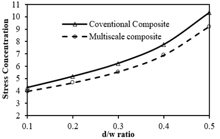
Figure 10 shows the effect of cutout size on the stress concentration in a composite plate with central circular cutout for both conventional and multiscale composites. From the results it is observed that multiscale composites consistently give lesser values of stress concentration than conventional composites for all d/w ratios. At d/w=0.1, the stress concentration reduced by 7% for multiscale composite plate than conventional composite plate. As the cutout size increases the stress concentration reduces and at d/w=0.5, the stress concentration reduced by 13% for multiscale composites than the conventional composites. Same trend is observed with plates having elliptical holes (Figures 11 and 12) of two configurations. Due to the addition of CNT reinforcement in glass fiber composites, the maximum percentage reduction in stress concentration is observed in case of plate containing central elliptical cutout with transverse major axis, while in the plate with circular cutout moderate reduction and less reduction in case of plate containing elliptical cutout with longitudinal major axis.
Figure 10. Variation of stress concentration with d/w ratio in a composite plate with circular cutout
Figure 11. Variation of stress concentration with a/w ratio in a composite plate containing elliptical cutout at the center with longitudinal major axis
Figure 12. Variation of stress concentration with a/w ratio in a composite plate containing elliptical cutout with transverse major axis
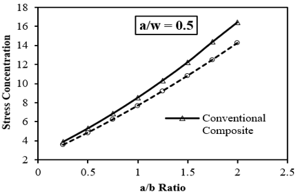
Figure 13. Variation of stress concentration with a/b ratio in a composite plate containing central cutout with longitudinal major axis
The variation of stress concentration with a/b ratio in a composite plate with elliptical cutout at the center with longitudinal major axis in case of both conventional and multiscale composite plates is shown in Figure 13. The results reveal that as a/b ratio increases, the stress concentration decreases for both the composite plates but, the multiscale composites give lesser values of stress concentration.
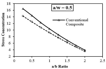
Figure 14. Variation of stress concentration in a composite plate containing central cutout with transverse major axis
The variation of stress concentration with respect to a/b ratio for both the conventional and multiscale composite plates having elliptical cutout at the center with transverse major axis is given in Figure 14. From the results it is observed that as a/b ratio increases, the stress concentration increases for both the composite plates but, the multiscale composites consistently give lesser values of stress concentration. So, there is a significant effect on stress concentration due to change in a/b ratio for both the conventional and multiscale composite plates.
In depth investigations disclose that the reduction in stress concentration in multiscale composites is due to increase in stiffness by the reinforcement of CNTs into glass fiber composites. These investigations show that CNT reinforcement in glass fiber composites improves structural performance.
The effect of CNT embedment on the stress concentration in multiscale composite plates having cutout at the center loaded in a plane has been examined using finite element method. Maximum values of stress concentration are observed in conventional composite plate containing central hole. The results also reveal that percentage increase in stress concentration is less in CNT based multiscale composites compared to conventional composites.
[1] Iijima, S. (1991). Helical microtubules of graphitic carbon. Nature, 354: 56-58. http://doi.org/10.1038/354056a0
[2] Liu, Y.J., Chen, X.L. (2003). Evaluations of the effective material properties of carbon nanotube-based composites using a nanoscale representative volume element. Mechanics of Materials, 35: 69-81. https://doi.org/10.1016/S0167-6636(02)00200-4
[3] Song, Y.S., Youn, J.R. (2006). Modeling of effective elastic properties for polymer-based carbon nanotube composites. Polymer, 47: 1741-748. https://doi.org/10.1016/j.polymer.2006.01.013
[4] Banerjee, D., Nguyen, T., Chuang, T. (2016). Mechanical properties of single-walled carbon nanotube reinforced polymer composites with varied interphase’s modulus and thickness: A finite element analysis study. Computational Material Science, 114(1-25): 209-218. https://doi.org/10.1016/j.commatsci.2015.12.026
[5] Gupta, A.K., Harsha, S.P. (2014). Analysis of mechanical properties of carbon nanotube reinforced polymer composites using continuum mechanics approach. Procedia of Material Science, 6: 18-25. https://doi.org/10.1016/j.mspro.2014.07.004
[6] Govindjee, S., Sackman, J.L. (1999). On the use of continuum mechanics to estimate the properties of nanotubes. Solid State Communications, 110(4): 227-230. https://doi.org/10.1016/S0038-1098(98)00626-7
[7] Frankland, S.J.V., Harik, V.M., Odegard, G.M., Brenner, D.W., Gates, T.S. (2003). The stress–strain behavior of polymer–nanotube composites from molecular dynamics simulation. Composites Science and Technology, 63(11): 1655-1661. https://doi.org/10.1016/S0266-3538(03)00059-9
[8] Zhu, R., Pan, E., Roy, A.K. (2007). Molecular dynamics study of the stress-strain behavior of carbon-nanotube reinforced Epon 862 composites. Material Science and Engineering, 447: 51-57. https://doi.org/10.1016/j.msea.2006.10.054
[9] Shamsieva, A., Evseev, A., Piyanzina, I., Nedopekin, O., Tayurskii, D. (2023). Molecular dynamics modeling for the determination of elastic moduli of polymer–single-walled carbon nanotube composites. International Journal of Molecular Sciences, 24:11807. https://doi.org/10.3390/ijms241411807
[10] Han, Y., Elliott, J. (2007). Molecular dynamics simulations of the elastic properties of polymer/carbon nanotube composites. Computational Materials Science, 39:315-323. https://doi.org/10.1016/j.commatsci.2006.06.011
[11] Xu, X., Sun, L., Fan, X. (1995). Stress concentration of finite composite laminates with elliptical hole. Computers & Structures, 57(1): 29-34. https://doi.org/10.1016/0045-7949(94)00588-T
[12] Khechai, A., Tati, A., Guettala, A. (2014). Finite element analysis of stress concentrations and failure criteria in composite plates with circular holes. Frontiers of Mechanical Engineering, 9: 281-294. https://doi.org/10.1007/s11465-014-0307-9.
[13] Sathurusinghe S.A.S.P., Herath, W.M.N.A.P.B., Subhashini, H.A.R., Kumara, A.M.C.S.S., Herath, K.R.B. (2012). Stress concentrations in single walled carbon nanotube reinforced metal and polymer composites under uniaxial loading. International Journal of Advanced Structures and Geotechnical Engineering, 1(2): 58-60.
[14] Tzeng, S.H., Tsai, J.L. (2011). Investigating the stress distribution of single walled carbon nanotubes embedded in polyimide nanocomposites. Journal of Reinforced Plastics and Composites, 30(11): 922-931. https://doi.org/10.1177/0731684411421637
[15] Liu, S.J., Her, S.C. (2013). Stress analysis of carbon nanotubes reinforced nanocomposites. Applied Mechanics and Materials, 284-287: 357-361. https://doi.org/10.4028/www.scientific.net/AMM.284-287.357
[16] Wang, S.Y., Zhang, P.Z., Zhang, N., Wei, D.B., Wei, X.X. (2019). An image-driven finite element modeling method for evaluating the stress and strain distribution in carbon nanotubes/epoxy composites. Materials Research Express, 6(12): 125611. http://doi.org/10.1088/2053-1591/ab54b5
[17] Zeighami, V., Jafari, M. (2022). Using Laurent’s series in the theoretical solution to estimate the stress resultants of FG-CNTRC plates weakened by a central cutout at different temperatures. International Journal for Computational Methods in Engineering Science and Mechanics, 24(4): 227-246. https://doi.org/10.1080/15502287.2022.2150721
[18] Fan, C.S., Lin, C., Hwu, C. (2009). Numerical estimation of the mechanical properties of CNT-reinforcing composites. Proceedings of Fifth Taiwan-Japan Work Shop on Mechanical and Aerospace Engineering, Nantou, Taiwan.
[19] Agarwal, B.D., Broutman, L.J. (1990). Analysis and performance of fiber composites. The Aeronautical Journal. John Wiley & Sons, Inc., USA.
[20] Greszczuk, L.B. (1972). Stress concentrations and failure criteria for orthotropic and anisotropic plates with circular openings. Composite Materials: Testing and Design, American Society for Testing and Materials, 363-381.