
Gérardine Sibomana* | Ilias Mouallif | Hind Abdellaoui | Hachim Abdelilah | Ibrahim Haddouch
© 2026 The authors. This article is published by IIETA and is licensed under the CC BY 4.0 license (http://creativecommons.org/licenses/by/4.0/).
OPEN ACCESS
ANSYS Material Designer was used to evaluate and optimize the effect of fiber volume fraction (Vf) on the elastic properties of unidirectional carbon fiber reinforced polymer (UD-CFRP). The objective was to improve stiffness while reducing deformation and weight for aeronautic, marine, and automotive sectors. A representative volume element (RVE) model was created in ANSYS Material Designer to simulate a range of fiber volume fractions, and a homogenization approach was used to compute elastic properties. A multi-objective genetic algorithm (MOGA) was then applied to identify optimal variables and to maximize stiffness while minimizing deformation and weight. The results indicate that increasing fiber volume fraction linearly enhances the longitudinal and transverse Young’s modulus and the shear moduli, while it decreases the in-plane Poisson’s ratio, with an average coefficient of determination of 99% for the Young's and shear moduli (98.9%-100%) and Poisson’s ratio (in-plane R2 = 99%, out-of-plane R2 = 55.9%, average 77%). Comparison with micromechanical equations confirms that the rule of mixtures (ROM) predicts the longitudinal modulus within 0.05%, while the transverse and shear moduli from the RVE homogenization are up to 22% higher than the corresponding closed-form inverse ROM estimates. Together, these results provide a validated, quantitative framework for selecting an appropriate fiber volume fraction and an appropriate micromechanical model for a target UD-CFRP application.
elastic properties, unidirectional carbon fiber reinforced polymer, fiber volume fraction, ANSYS Material Designer, multi-objective genetic algorithm optimization, representative volume element, transverse isotropy
Fiber reinforced composite materials are increasingly employed across the aeronautics, infrastructure, and automotive sectors. Their main advantages over conventional structural materials are specific properties such as reduced weight, high stiffness, strength, and corrosion resistance. Carbon Fibers, in particular, are widely used as reinforcement to improve the mechanical performance of aircraft structural components, and fiber reinforced composites are now among the most common materials used in structural applications. Homogenization of composite material is the first step in the design and analysis process of composite material properties [1-3]. It replaces a heterogeneous material with an equivalent homogeneous one [4] to estimate the elastic properties of the composite, such as the longitudinal, transverse, and vertical direction Young's modulus, the in-plane and out-of-plane shear moduli, and the in-plane and out-of-plane Poisson's ratios.
Several authors have investigated the models of homogenization based on the representative volume element (RVE) approach [1, 4, 5] to assess the elastic properties of composite materials [6, 7]. However, numerical methods [4] that account for the exact geometry of the reinforcement and for realistic boundary conditions remain complex to implement. For these problems, defining an RVE geometry [8] within the ANSYS module makes it possible to estimate the stiffness of the composite while reducing the weight [9].
The objective of this study is to assess and optimize the influence of fiber volume fraction (Vf) on the elastic properties of unidirectional carbon fiber reinforced polymer (UD-CFRP, carbon/Resin epoxy), to enhance stiffness while reducing weight and deformation. In UD-CFRP, the Carbon Fibers are aligned in a single direction so that the mechanical performance can be optimized along the primary loading path. This configuration provides superior properties compared to woven fiber systems [10], making manufacturing UD-CFRP particularly suitable for aeronautic, automotive, and high-performance structural components. Material data found in the literature and in the ANSYS Material Designer engineering data library were used for the modeling, systematic analysis, and optimization of composite materials based on their constituent properties. Higher fiber volume fractions are generally found to improve the elastic properties of the composite material, and this increase is typically linear, improving stiffness. The relationship is significantly important for optimizing composite material performance across various applications. However, relatively few studies have addressed the modeling of elastic properties for UD-CFRP specifically using ANSYS Material Designer, which motivates the present work.
The work aims to evaluate the effect of fiber volume fraction on the elastic properties of UD-CFRP, to maximize the stiffness while reducing deformation and weight. The UD-CFRP was first modeled, after which a multi-objective genetic algorithm (MOGA) optimization method was carried out in the ANSYS Material Designer module. The following subsections, 2.1 and 2.2, describe the materials and methods used in this investigation.
2.1 Material
The constituent material used for the homogenization and optimization was selected from the ANSYS Workbench Engineering Data Library, based on data reported in the literature. The matrix was a Resin-Epoxy [3], modeled as an Isotropic Material, and the reinforcement was Carbon Fiber (230000 MPa) [11, 12], modeled as an Orthotropic Material. Both Carbon Fiber and Resin Epoxy are widely used and well characterized in composite materials research. Table 1 presents the properties of the Resin Epoxy and Carbon Fiber used in this work, along with a description of each material's constants.
Table 1. Properties of the resin epoxy and carbon fibers, and their description
|
Property |
Value |
Unit |
Meaning |
|
Carbon fiber |
|||
|
$\rho_f$ |
1800 |
Kg/m3 |
density |
|
Orthotropic elasticity |
|||
|
$E_{1 f}$ |
230000 |
MPa |
Longitudinal Young’s modulus (x direction) |
|
$E_{2 f}$ |
23000 |
MPa |
Transverse Young’s modulus (Y direction) |
|
$E_{3 f}$ |
23000 |
MPa |
Vertical Young’s modulus (Z direction) |
|
$n u_{12 f}$ |
0.2 |
- |
In-Plane Poisson’s ratio XY, parallel to the Fiber axis |
|
$n u_{13 f}$ |
0.2 |
- |
Out-of-Plane Poisson’s ratio XZ |
|
$n u_{23 f}$ |
0.4 |
- |
Out-of-Plane Poisson’s ratio YZ, perpendicular to the Fiber axis. |
|
$G_{12 f}$ |
9000 |
MPa |
In-plane shear moduli XY, parallel to the Fiber axis |
|
$G_{31 f}$ |
9000 |
MPa |
Out-of-Plane shear moduli ZX |
|
$G_{23 c}$ |
28210 |
MPa |
Out-of-Plane shear moduli YZ |
|
Matrix: resin epoxy |
|||
|
$\rho_m$ |
1160 |
Kg/m3 |
density |
|
Isotropic elasticity |
|||
|
$E_m$ |
3780 |
MPa |
Matrix Young’s modulus |
|
$n u_m$ |
0.35 |
- |
Matrix Poisson’s ratio |
|
$G_m$ |
1400 |
MPa |
Matrix shear moduli |
2.2 Representative volume element geometry
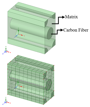
ANSYS Material Designer [9] was used to assess the influence of fiber volume fraction on the elastic properties of unidirectional reinforced composites. Modeling the RVE [5, 13, 14] is the first step of the homogenization method. As shown in Figure 1, a hexagonal RVE was considered for the unidirectional composite materials to evaluate their elastic properties using the rule of mixtures (ROM). A blocked, conformal mesh with a maximum element size of 0.002 mm based on study [15] was used, and the default boundary conditions of the ANSYS Material Designer Library were applied. Elastic properties were computed for fiber volume fractions of 0.05, 0.06, 0.07, 0.08, 0.09, 0.1, 0.2, 0.3, 0.4, and 0.5. RVE response is characterized by nine parameters: the three Young’s modulus $E_{1 c}, E_{2 c}$, and $E_{3 c}$; the three shear moduli $G_{12 c}, G_{13 c}$, and $G_{23 c}$, and finally the three Poisson’s ratio $n u_{12 c}, n u_{13 c}$, and $n u_{23 c}$. The optimized responses are calculated to obtain the homogenized optimum for UD-CFRP material data.
Figure 1. Geometry of representative volume element (RVE) with a hexagonal fiber and the corresponding mesh ($V_f$ = 0.37, $D_f$ = 0.005 mm)
The fiber-matrix interface was assumed to be perfectly bonded; no interfacial debonding or cohesive damage model was included, as the homogenization module used does not support interface modeling. Periodic boundary conditions were applied to the hexagonal RVE, as directly confirmed by the ANSYS Material Designer analysis settings (use periodic boundary conditions = true; type of Anisotropy = orthotropic). A mesh-sensitivity study was conducted at the recommended design point ($V_f$ = 0.37, $D_f$ = 0.005 mm) using element sizes of 0.001, 0.002, and 0.003 mm (Table 2); all homogenized elastic constants varied by less than 0.7% across this range, confirming that the 0.002 mm (2 µm) mesh adopted throughout the study provides mesh-independent results.
Table 2. Mesh-sensitivity study on the homogenized elastic constants at $V_f$ = 0.37, $D_f$ = 0.005 mm
|
Elasticity Properties |
0.001 mm |
0.002 mm |
0.003 mm |
|
$E_{1 c}$ [MPa] |
87503 |
87442 |
87442 |
|
$E_{2 c}$ [MPa] |
6815.9 |
6829.8 |
6846 |
|
$E_{3 c}$ [MPa] |
6815.9 |
6829.8 |
6846 |
|
$G_{12 c}$ [MPa] |
2437.8 |
2436.9 |
2437.8 |
|
$G_{23 c}$ [MPa] |
2290.8 |
2297.9 |
2304.7 |
|
$G_{13 c}$ [MPa] |
2437.8 |
2436.9 |
2437.8 |
|
$n u_{12 c}$ |
0.28761 |
0.2876 |
0.28761 |
|
$n u_{23 c}$ |
0.48762 |
0.48642 |
0.48527 |
|
$n u_{13 c}$ |
0.28761 |
0.2876 |
0.28761 |
|
$\rho$ [kg/m3] |
1397 |
1397 |
1397 |
Here, $E_{1 f}, E_{2 f}$, and $E_{3 f}$ are the Young’s modulus of the UD-CFRP in the longitudinal, transverse, and vertical directions. $G_{12 f}$ is the in-plane shear moduli(longitudinal-transverse), $G_{31 f}$ is the shear moduli relating the vertical and longitudinal directions, and $G_{23 f}$ is the shear moduli in the transverse and vertical directions. Similarly, $n u_{12 C}$ is the Poisson’s ratio transverse to the longitudinal direction, $n u_{13 f}$ relates Poisson’s ratio in the vertical to the longitudinal direction, and $n u_{23 f}$ relates Poisson’s ratio in the vertical to the transverse direction.
Figure 1 shows the geometry of the RVE used to compute Young’s modulus, shear moduli, and Poisson’s ratio in the vertical, longitudinal, and transverse directions.
2.3 Optimization multi-objective genetic algorithm
Optimization methods [16] are widely applied in science and engineering branches. An Optimization process seeks a large design space by iteratively improving on the current candidate solutions. Multi-objective optimization Algorithms have gained wide acceptance for their ability to efficiently approximate solutions to problems with several, often competing, objectives [17]. In this study, the design exploration environment of ANSYS was used in conjunction with ANSYS Material Designer. A Design of Experiments and a response surface [18, 19] were built to find the optimal fiber volume fraction, fiber diameter, and resulting elastic properties and weight of the RVE material. MOGA is an evolutionary optimization approach suited to problems with several objectives [16]. In this study, Young’s modulus, shear moduli, and Poisson’s ratio are treated as objectives to be maximized or minimized appropriately, while the weight is minimized. The design variables, parameters, bounds, and optimization objective are recapitulated in the following Table 3.
Table 3. Design variables, parameters, bounds, and optimization objectives
|
Design Variables |
Parameter |
Unit |
Bounds/Value |
Objective |
|
Material designer |
|
|
|
|
|
Matrix (resin epoxy) |
- |
- |
Constant |
- |
|
Carbon fiber |
|
|
Variable |
- |
|
fiber volume fraction |
$V_f$ |
- |
$0.04<V_f<0.7$ |
|
|
Fiber diameter |
$D_f$ |
mm |
$0.001<D_f<0.010$ |
|
|
Length ratio |
$L r$ |
- |
Constant= 2 |
- |
|
Repeat count |
$r c$ |
- |
Constant=1 |
- |
|
Objective functions |
|
|
|
|
|
Young’s modulus, X |
$E_{1 c}$ |
MPa |
- |
Maximize |
|
Young’s modulus, Y |
$E_{2 c}$ |
MPa |
|
Maximize |
|
Young’s modulus, Z |
$E_{3 c}$ |
MPa |
- |
Maximize |
|
shear moduli, XY |
$G_{12 c}$ |
MPa |
- |
Maximize |
|
shear moduli, YZ |
$G_{23 c}$ |
MPa |
- |
Maximize |
|
shear moduli, XZ |
$G_{13 c}$ |
MPa |
- |
Maximize |
|
Poisson’s ratio, XY |
$n u_{12 c}$ |
|
- |
Minimize |
|
Poisson’s ratio, YZ |
$n u_{23 c}$ |
|
- |
Minimize |
|
Poisson’s ratio, XZ |
$n u_{13 c}$ |
|
- |
Minimize |
|
density |
$\rho_{e q}$ |
kg/m3 |
- |
Minimize |
The MOGA optimization was configured with an initial sample of 3000 design points, 600 additional samples generated per iteration, and a maximum of 20 iterations. Convergence was assessed against two software-defined criteria: a Maximum Allowable Pareto Percentage of 70% and a Convergence Stability Percentage of 2%. The optimization was declared converged after 5 iterations (5081 total evaluations), at which point the solver-reported Pareto Percentage (0.167%) and Stability Percentage (1.36%) had both fallen below their respective thresholds, yielding 3 candidate design points (Section 3). The crossover and mutation probabilities were kept at the DesignXplorer default settings, as they are not exposed as separate configurable parameters in the module’s properties panel.
The elastic properties can be evaluated within a response surface environment and serve as optimization objectives. Additionally, the elasticity properties and the density objective function can be related to the constituent properties through the following micromechanical relationship [4, 12, 20, 21]:
Longitudinal properties:
$E_{1 C}=V_f E_{1 f}+V_m E_m$ (1)
$n u_{2 c}=V_f n u_{12 f}+V_m n u_m$ (2)
Transverse and vertical properties:
$E_{2 c}=E_{3 c}=\frac{E_{2 f} E_m}{E_{2 f} V_m+E_m V_f}$ (3)
Shear moduli:
$G_{12 C}=G_{31 C}=\frac{G_{12 f} G_m}{G_{12 f} V_m+G_m V_f}$ (4)
$G_{23 c}=\frac{G_{23 f} G_m}{G_{23 f} V_m+G_m V_f}$ (5)
Density objective function:
$\rho_{e q}=\rho_f V_f+\left(1-V_f\right) \rho_m$ (6)
where, $V_f$ and $V_m$ are the fiber and matrix volume fractions, respectively; $E_{1 f}, E_{2 f}, E_{3 f}$ are the Young's modulus of the fiber, and $E_m$ is the Young's modulus of the matrix; $G_{12 f}, G_{31 f}, G_{23 f}$ are the shear moduli of the fiber and $G_m$ is the shear moduli of the matrix; $n u_{12 f}$ is the Poisson's ratio of the fiber and $n u_m$ is the Poisson's ratio of the matrix; $E_{1 c}, E_{2 c}, E_{3 c}$ are the Young's Modulus of the composite; $G_{12 c}, G_{31 c}, G_{23 c}$ are the shear moduli of the composite; $n u_{12 c}, n u_{13 c}, n u_{23 c}$ are the Poisson's ratio of the composite; $\rho_{e q}$ is the equivalent density of composite material.
The closed-form micromechanical estimates of Eqs. (1)-(6) are given here as reference bounds. Section 3.5 provides a quantitative comparison with the RVE-homogenized values of Table 4, clarifying which properties they reliably predict and which they do not.
Table 4. Elastic properties of the unidirectional carbon fiber reinforced polymer (UD-CFRP) according to fiber volume fraction
|
$V_f$ |
$E_{1 c}$ [MPa] |
$E_{2 c}$ [MPa] |
$E_{3 c}$ [MPa] |
$G_{12 c}$ [MPa] |
$G_{23 c}$ [MPa] |
$G_{31 c}$ [MPa] |
$n u_{12 c}$ |
$n u_{13 c}$ |
$n u_{23 c}$ |
$\rho_{e q}$ [kg/m3] |
|
0.05 |
15088 |
4411.2 |
4411.2 |
1506.2 |
1489.6 |
1506.2 |
0.341 |
0.341 |
0.48091 |
1192 |
|
0.06 |
17349 |
4483 |
4483 |
1528.5 |
1508.3 |
1528.5 |
0.33923 |
0.33923 |
0.48642 |
1198 |
|
0.07 |
19611 |
4551.5 |
4551.5 |
1551 |
1527.3 |
1551 |
0.33746 |
0.33746 |
0.49045 |
1201 |
|
0.08 |
21872 |
4619.2 |
4619.2 |
1573.9 |
1546.7 |
1573.9 |
0.3357 |
0.33569 |
0.49335 |
1211 |
|
0.09 |
24133 |
4684 |
4684 |
1597.1 |
1566.4 |
1597.1 |
0.33394 |
0.33394 |
0.49567 |
1218 |
|
0.1 |
26395 |
4749.6 |
4749.6 |
1620.8 |
1586.5 |
1620.8 |
0.3322 |
0.33219 |
0.49729 |
1224 |
|
0.2 |
49007 |
5417.9 |
5417.9 |
1879.3 |
1806.8 |
1879.3 |
0.3151 |
0.31515 |
0.50011 |
1288 |
|
0.3 |
71616 |
6194.8 |
6194.8 |
2186.3 |
2074.7 |
2186.3 |
0.29871 |
0.29879 |
0.49317 |
1352 |
|
0.4 |
94223 |
7159.9 |
7159.7 |
2559.4 |
2426.1 |
2559.4 |
0.28265 |
0.28379 |
0.48093 |
1416 |
|
0.5 |
116880 |
8375.2 |
8375.2 |
3016.1 |
2848.5 |
3016.1 |
0.26775 |
0.26775 |
0.46621 |
1480 |
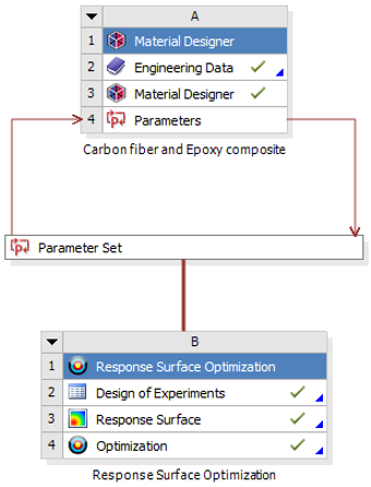
The corresponding numerical workflow from the material designer to Response Surface Optimization is presented in Figure 2.
Figure 2. Workflow for the numerical analysis and response surface optimization
Two-dimensional and three-dimensional response surfaces were used to assess the effect of fiber volume fraction on the Young’s modulus, shear moduli, and Poisson’s ratio of the UD-CFRP. Ten configurations of the fiber volume fractions were considered: 0.05, 0.06, 0.07, 0.08, 0.09, 0.1, 0.2, 0.3, 0.4, 0.5. Table 4 presents the resulting elastic properties for each fiber volume fraction, corresponding to the RVE model shown in Figure 1. The optimization aimed to maximize the fiber volume fraction, fiber diameter, Young’s modulus, and shear moduli, while minimizing Poisson’s ratio and density. The design variables obtained from the MOGA optimization of the RVE model are reported in Tables 3, 5, 6, and 7.
3.1 Material designer samples generation and optimization
The elastic properties of the UD-CFRP were determined for the RVE at each fiber volume fraction based on reference [4], as shown in Tables 4 and 5.
The MOGA candidate solutions converge toward $V_f=$ 0.69, which corresponds to the upper edge of the design-space bound imposed in Table 3 $\left(0.04<V_f<0.70\right.)$, rather than to the theoretical close-packing limit of a hexagonal fiber arrangement, $\left(V_{f, \max}=\frac{\pi}{2 \sqrt{3}}=0.9065\right)$. However, practical manufacturing constraints typically limit the achievable $V_f$ to 0.55-0.65 for high-performance aerospace CFRP laminates [13, 22]. The candidate points at $V_f=0.69$ should therefore be interpreted as the mathematical optimum of the objective space rather than a directly manufacturable configuration. The response point at $V_f=0.37$ was therefore evaluated on the fitted response surface as a custom, deliberately conservative design point (Table 6), not itself an output of the MOGA search, but a practically motivated recommendation situated well below even the 0.55-0.65 manufacturability ceiling. This choice reflects the inherent conflict between the optimization objectives: increasing $V_f$ raises every stiffnessrelated property $\left(E_{1 c}, E_{2 c}, G_{12 c}, G_{23 c}\right)$ and lowers the in-plane Poisson's ratio, but it also increases the density objective $\rho$ eq and, above the manufacturable range, the risk of processinduced defects that are not captured by the elastic-property model. Selecting $V_f=0.37$ therefore trades part of the maximum achievable stiffness gain for a substantial safety margin against this manufacturing variability, while remaining well within the low-density, high-quality processing window suited to both aerospace and automotive UD-CFRP applications.
Table 5. Design of experiments (optimization)
|
$V_f$ |
$D_f$ [mm] |
$E_{1 c}$ [MPa] |
$E_{2 c}$ [MPa] |
$G_{12 c}$ [MPa] |
$G_{23 c}$ [MPa] |
$n u_{12 c}$ |
$n u_{23 c}$ |
$\rho_{e q}$ [kg/m3] |
|
0.37 |
0.0055 |
87493 |
6819 |
2437 |
2294 |
0.28 |
0.48 |
1390 |
|
0.04 |
0.0055 |
12831 |
4333 |
1484 |
1470 |
0.34 |
0.47 |
1180 |
|
0.37 |
0.001 |
87441 |
6851 |
2437 |
2304 |
0.28 |
0.48 |
1390 |
|
0.37 |
0.01 |
87502 |
6815 |
2437 |
2290 |
0.28 |
0.48 |
1390 |
|
0.37 |
0.0055 |
87493 |
6819 |
2437 |
2294 |
0.28 |
0.48 |
1390 |
|
0.37 |
0.0055 |
87493 |
6819 |
2437 |
2294 |
0.28 |
0.48 |
1390 |
|
0.2 |
0.003 |
51224 |
5493 |
1907 |
1832 |
0.31 |
0.49 |
1290 |
|
0.2 |
0.007 |
51259 |
5480 |
1907 |
1826 |
0.31 |
0.5 |
1290 |
|
0.5 |
0.007 |
123740 |
8733 |
3173 |
2980 |
0.26 |
0.46 |
1490 |
|
0.2 |
0.003 |
51224 |
5493 |
1907 |
1832 |
0.31 |
0.49 |
1290 |
|
0.2 |
0.007 |
51259 |
5480 |
19071 |
1826 |
0.31 |
0.5 |
1290 |
|
0.5 |
0.004 |
123740 |
8734 |
3173 |
2980 |
0.26 |
0.46 |
1490 |
Table 6. Conservative design recommendation (response-surface point)
|
Input |
Output |
|||||||
|
$V_f$ |
$D_f$ [mm] |
$E_{1 c}$ [MPa] |
$E_{2 c}=E_{3 c}$ [MPa] |
$G_{12 c}=G_{31 c}$ [MPa] |
$G_{23 c}$ [MPa] |
$n u_{12 c}=n u_{13 c}$ |
$n u_{23 c}$ |
$\rho_{e q}$ [kg/m3] |
|
0.37 |
0.005 |
87492 |
6839 |
2440 |
2290 |
0.28 |
0.487 |
1400 |
Table 7. Candidate optimization points
|
Point |
$V_f$ |
$D_f$ [mm] |
$E_{1 c}$ [MPa] |
$E_{2 c}$ [MPa] |
$G_{12 c}$ [MPa] |
$G_{23 c}$ [MPa] |
$n u_{12 c}$ |
$n u_{23 c}$ |
$\rho_{e q}$ [kg/m3] |
|
1 |
0.69 |
0.0098 |
162000 |
11412 |
4178 |
4000.5 |
0.239 |
0.438 |
1610 |
|
2 |
0.69 |
0.0099 |
162000 |
11416 |
4181 |
4002 |
0.239 |
0.438 |
1610 |
|
3 |
0.69 |
0.0099 |
162000 |
11416 |
4181 |
4002 |
0.239 |
0.438 |
1610 |
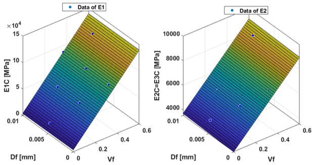
Figure 3. Stiffness as a function of fiber volume fraction and fiber diameter ($V_f, D_f$)
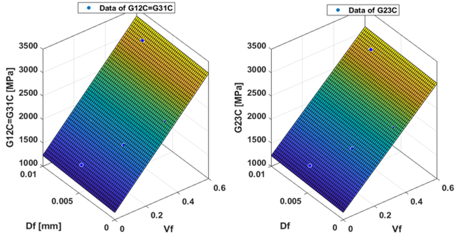
Figure 4. In-plane and out-of-plane shear moduli as a function of fiber volume fraction and fiber diameter ($V_f, D_f$)
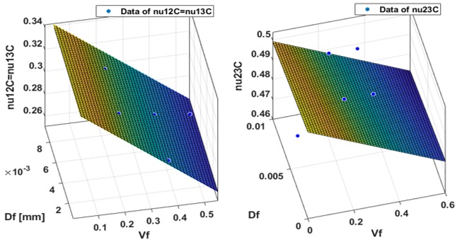
Figure 5. Poisson’s ratio as a function of fiber volume fraction and fiber diameter ($V_f, D_f$)
The results of the response surface points are reported in Table 6. The maximum longitudinal Young’s modulus is 87492 MPa, and the transverse is 6839 MPa. The minimum equivalent density of the Unidirectional CFRP RVE is 1400 kg/m3, obtained for a fiber diameter of 0.0055 mm. Figure 3 shows the response surface curves during the optimization of Young's modulus, and the corresponding correlation between fiber volume fraction and Young’s modulus is discussed in Section 3.2.
Figure 4 shows the optimization results for the in-plane shear moduli ($G_{12 C}=G_{13 C}$) and the out-of-plane shear moduli ($G_{23 C}$) as a function of fiber volume fraction and fiber diameter. Both modulus increase with fiber volume fraction, confirming that fiber content has the most effect on the stiffness of the composite. The response design point corresponds to 2440 MPa for the in-plane shear moduli and 2290 MPa for the out-of-plane shear moduli. The corresponding correlation between shear moduli and fiber volume fraction is discussed in Section 3.3.
The response surface point of Poisson’s ratio is 0.28 in-plane and 0.487 out-of-plane, as reported in Table 6. Figure 5 shows the design of experiments results obtained during the optimization process of Poisson’s ratio. The results show that increasing the fiber volume fraction decreases Poisson’s ratio and thereby reduces the deformation of the unidirectional composite.
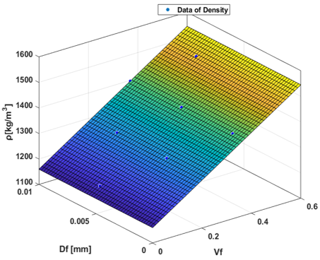
Figure 6. Density (r) according to fiber volume fraction and fiber diameter ($V_f, D_f$)
Figure 6 shows the equivalent density of the composite over the explored ranges of fiber volume fraction and fiber diameter. Density is strongly correlated with fiber volume fraction, and the response surface point identified a minimum density of 1400 kg/m3.
3.2 Two-dimensional response of the Young’s modulus
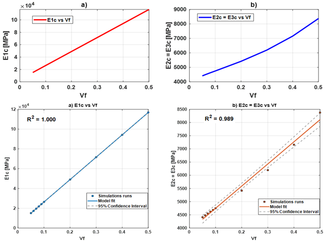
For the different fiber volume fractions listed in Table 4, the effect of fiber volume fraction [1] on Young's modulus and the correlation [23] between these two parameters were analyzed. For the longitudinal and transverse directions, the Young's Modulus ($E_{1 c}, E_{2 c}, E_{3 c}$) increase proportionally with the fiber volume fraction of the Unidirectional composite, with a noticeable acceleration trend at higher volume fractions (Figure 7). The dominant role of fiber content in the longitudinal direction is explained by the large stiffness contrast between carbon fiber ($E_{1 f}=230000$ MPa) and epoxy matrix ($E_m=3780$ MPa), a ratio of approximately 61:1. Under longitudinal loading, fibers and matrix deform compatibly (iso-strain assumption), so the ROM governs: each unit of fiber added to the composite directly replaces a unit of low-stiffness matrix with high-stiffness reinforcement, yielding a nearly linear increase in $E_{1 c}$ with $V_f$. The transverse modulus $E_{2 c}$ also increases with $V_f$, but at a significantly lower rate. Under transverse loading, the matrix remains the load-bearing path between fibers: stress must transfer through the matrix-fiber-matrix sequence, so the effective stiffness is governed by an iso-stress (series) mechanism rather than the iso-strain (parallel) mechanism of the longitudinal direction. Consequently, $E_{2 c}$ is far more sensitive to matrix stiffness and fiber-matrix interface conditions than to fiber modulus alone. The full-field RVE solution captures this two-dimensional load sharing explicitly, yielding transverse modulus 10–22% higher than the inverse ROM, as demonstrated in Section 3.5.
Figure 7. Influence of fiber volume fraction on the longitudinal and transverse Young’s Modulus ($E_{1 c}, E_{2 c}=E_{3 c}$)
Fiber volume fraction has the most significant influence on the longitudinal Young's modulus ($E_{1 c}$), and the relationship between the two parameters shows an excellent goodness of fit with an $\mathrm{R}^2$ equal to 100%. In the vertical and transverse directions, the Young's modulus $\left(E_{2 c}=E_{3 c}\right)$ is also significantly influenced by fiber volume fraction and shows a goodness-of-fit $R^2=98.9 \%$. The correlation between the results is excellent, almost perfect. This means that the RVE made in ANSYS Material Designer behaves like it should when it comes to composites. It shows that the homogenization process gets the stiffness of the material right for different amounts of fibers. The RVE and the homogenization process therefore provide a reliable prediction of the material response. It should be noted that the $R^2$ values shown above are the degree of fit of each elastic property to a regression trend with fiber volume fraction and not the degree of fit of the closed-form micromechanical Eqs. (1)-(6) to the RVE-homogenized values, which is analyzed in Section 3.5.
3.3 In-plane and out-of-plane shear moduli
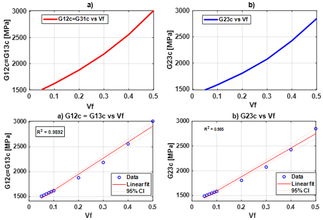
The RVE-based shear moduli predicted by ANSYS Material Designer shows excellent agreement with published experimental and numerical data for UD-CFRP [24, 25]. In-plane shear moduli $G_{12 c}=G_{31 c}$ by transverse isotropy, the RVE model predicts a progressive stiffening of the composite with increasing fiber content. Figure 8 shows a slight overestimation of the out-of-plane shear moduli ($G_{23 c}$) at higher volume fractions. For both shear moduli, fiber volume fraction is the dominant parameter, and the relationship between the two variables shows a goodness of fit, approximately $R^2=99 \%$.
Figure 8. In-plane and out-of-plane shear moduli according to volume fraction ($V_f$)
The increase in the in-plane and out-of-plane shear moduli is caused by the progressive restriction of the matrix deformation with the fiber content. The carbon fibers have much higher resistance to shear deformation than the epoxy matrix. The average distance between neighboring fibers decreases with increasing fiber volume fraction, which improves the efficiency of stress transfer across the fiber-matrix interface. Thus, the composite has a higher resistance to shear loading.
The fiber orientation is connected with the higher sensitivity of $G_{12 c}$ than $G_{23 c}$. Fibers are active in resisting deformation under in-plane shear loading by axial stiffness, while the matrix still carries a significant portion of the load under transverse shear.
These results are fully consistent with classical micromechanical theories and previous numerical homogenization studies that identified the fiber volume fraction as the dominant parameter controlling the shear stiffness of composites.
3.4 In-plane and out-of-plane Poisson’s ratio
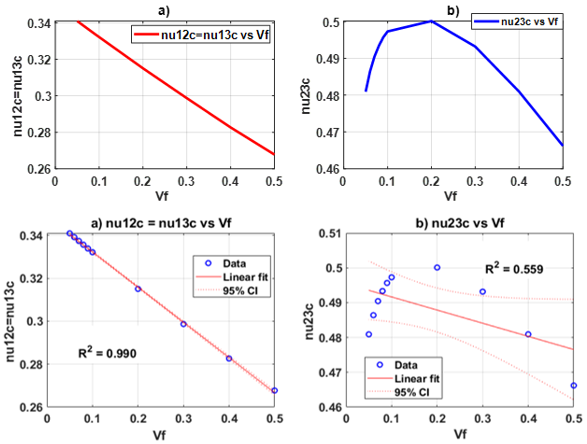
The in-plane Poisson’s ratio ($nu_{12 c}=nu_{13 c}$) decreases as fiber volume fraction increases. The out-of-plane $nu_{23 c}$ perpendicular to the fibers describes the out-of-plane behavior. Unlike Young’s modulus, Poisson’s ratio represents the lateral contraction of the composite when subjected to tensile loading. As the volume fraction of the fibers increases, the relatively incompressible carbon fibers slowly restrict the lateral deformation of the surrounding epoxy matrix. This mechanical constraint reduces the transverse strain, resulting in a gradual reduction of the effective Poisson's ratio. With low fiber volume fractions, the epoxy matrix is the dominant deformation mechanism with a large lateral contraction. The stiff fibers prevent the deformation of the matrix with increasing fiber content, which is why the Poisson’s ratio is observed to decrease in the numerical results. The lower coefficient of determination for $nu_{23 c}$ than for the elastic modulus indicates that the transverse deformation is determined by more complex interactions between fiber geometry, matrix behavior, and local stress redistribution that cannot be captured by purely linear relationships.
Figure 9 shows the influence of fiber volume fraction on the in-plane and out-of-plane Poisson’s ratio of the UD-CFRP. In-plane, the correlation between fiber volume fraction and Poisson’s ratio yields a goodness of fit of $R^2=99 \%$ , whereas out-of-plane the goodness of fit is only $R^2=55.9 \%$, reflecting the non-monotonic response noted above.
Figure 9. In-plane and out-of-plane Poisson’s ratio according to fiber volume fraction
3.5 Micromechanical comparison: Rule of mixtures comparison and cross-property elastic consistency check
The added value of the RVE-based numerical homogenization was evaluated in comparison to simplified analytical models by calculating the closed-form micromechanical predictions of Eqs. (1)-(6) for each fiber volume fraction of Table 4 and comparing the corresponding RVE-homogenized values. The complete comparison is presented in Appendix (Table A1). The main trends are summarized in Table 8 below.
Table 8. Selected comparisons between the ROM predictions of Eqs. (1) and (3), and the RVE-homogenized values of Table 4 (complete data in Appendix, Table A1)
|
$V_f$ |
$\mathbf{E}_{1 \mathrm{c}}~ \mathbf{R O M}$ [MPa] |
$\mathbf{E}_{1 \mathrm{c}}~ \mathbf{R V E}$ [MPa] |
$\Delta(\%)$ |
$\mathbf{E}_{2 \mathrm{c}}~ \mathbf{R O M}$ [MPa] |
$\mathbf{E}_{2 \mathrm{c}}~ \mathbf{R V E}$ [MPa] |
$\Delta(\%)$ |
|
0.05 |
15091 |
15088 |
-0.02 |
3945 |
4411 |
10.6 |
|
0.2 |
49024 |
49007 |
-0.03 |
4539 |
5418 |
16.2 |
|
0.5 |
116890 |
116880 |
-0.01 |
6493 |
8375 |
22.5 |
Eq. (1) predicts the longitudinal modulus $\mathrm{E}_{1 \mathrm{c}}$ to within $0.05 \%$ of the RVE-homogenized value over the full range of fiber volume fractions, confirming that the classical iso-strain (Voigt) ROM is essentially exact for the fiber-direction stiffness of a unidirectional composite, as reported in the review micromechanics of literature [24, 25]. On the contrary, the inverse rule of mixtures (inverse ROM) for the transverse modulus Eq. (3), and for the shear moduli Eqs. (4)-(5) systematically underpredicts the RVE results. The difference increases with fiber volume fraction: from about 10.6% at $V_f=5 \%$ to more than 22% for $\mathrm{E}_{2 \mathrm{c}}$ at $V_f=50 \%$ and from about 3% to nearly 20% for $G_{12 c}$ over the same range (Appendix, Table A1). This behavior is well documented in composite micromechanics, where the inverse ROM corresponds to a Reuss-type, iso-stress bound that is exact only for the longitudinal modulus and increasingly non-conservative for transverse and shear properties as it neglects the two-dimensional load-sharing and fiber-packing effects that are captured explicitly by a full-field RVE solution [25-27]. This comparison quantitatively demonstrates why the numerical RVE homogenization in Eqs. (3)-(5) is necessary to obtain reliable transverse and shear properties for UD-CFRP. Eqs. (1)-(6) should therefore be interpreted as reference micromechanical bounds, and not as the procedure to generate Table 4.
As an independent internal consistency check, the following relation, expected for a transversely isotropic unidirectional composite, was considered:
$G_{23 c}=\frac{E_{2 c}}{2\left(1+n u_{23 c}\right)}$ (7)
This transverse-isotropy relation, Eq. (7), was evaluated using the RVE-homogenized $E_{2 c}$ and $n u_{23 c}$ values of Table 4 and compared with the corresponding RVE-homogenized $G_{23 c}$. Predicted and homogenized values are within $0.4 \%$ throughout the entire range of fiber volume fraction studied (Appendix, Table A2), which is within the expected numerical precision of the response-surface fit. This agreement confirms the numerical consistency of the RVE homogenization, as well as the physical validity of modeling the UD-CFRP as a transversely isotropic material, which was assumed implicitly throughout this study, but not explicitly verified until now.
3.6 Comparison of current numerical study and published experimental data
To further assess the absolute accuracy of the RVE homogenization beyond the internal consistency checks of Section 3.5, the present results were compared with independently published experimental data for UD-CFRP reported by Qi et al. [28] at two fiber volume fractions ($V_f=0.6$ and $V_f=0.66$) for a carbon fiber system of comparable longitudinal modulus (230000 MPa). Table 9 summarizes the comparison.
Table 9. Comparison between the present representative volume element (RVE)- homogenized properties and published experimental data for unidirectional carbon fiber reinforced polymer (UD-CFRP)
|
$V_f$ |
Property |
Present RVE |
Experimental by Qi et al. [28] |
Error (%) |
|
0.6 |
$E_{1 c}$ [MPa] |
139530 |
138670 |
0.6 |
|
0.6 |
$E_{2 c}$ [MPa] |
9870 |
6999 |
41 |
|
0.6 |
$G_{12 c}$ [MPa] |
3597 |
3024 |
18.9 |
|
0.6 |
$G_{23 c}$ [MPa] |
3400 |
2379 |
43 |
|
0.66 |
$E_{1 c}$ [MPa] |
153100 |
149310 |
2.5 |
|
0.66 |
$E_{2 c}$ [MPa] |
11002 |
9090 |
21 |
|
0.66 |
$G_{12 c}$ [MPa] |
4003 |
5230 |
-23 |
|
0.66 |
$G_{23 c}$ [MPa] |
3820 |
3100 |
23.2 |
The longitudinal modulus $\mathrm{E}_{1 \mathrm{c}}$ shows excellent agreement with the published experimental data, with deviations of only $0.6 \%$ and 2.5% at $V_f=0.6$ and $V_f=0.66$, respectively, confirming that the RVE homogenization accurately captures the fiber-dominated longitudinal stiffness response. The transverse modulus $E_{2 c}$ and the shear moduli $G_{12 c}$ and $G_{23 c}$ show larger deviations, ranging from $19 \%$ to $43 \%$. This is attributed to the transverse and shear elastic constants of the generic carbon-fiber material entry used in the ANSYS Material Designer library, which are not published by the manufacturer and are therefore not independently verifiable, and which likely differ from those of the specific fiber grade used in the experimental reference. This pattern of close agreement for the fiber-governed longitudinal modulus and larger, transverse-constant-sensitive deviations for $E_{2 c}, G_{12 c}$ and $G_{23 c}$ is consistent with the broader micromechanics literature and is reported here as an identified limitation of the present homogenization rather than concealed.
This investigation demonstrates that the homogenization and optimization method implemented in ANSYS Material Designer effectively predicts the elastic properties of a unidirectional fiber reinforced composite. ANSYS Material Designer yields a robust approach for predicting the stiffness, weight, and deformation of UD-CFRP. A MOGA was used to maximize the elastic properties while minimizing the weight of the RVE model according to fiber volume fraction and fiber diameter, and the optimization process identified the optimal design point. However, the fiber volume fraction is found to have the strongest influence on the elastic properties of the composite. Young's modulus and shear moduli increase linearly with fiber volume fraction, while Poisson’s ratio decreases as the composite becomes stiffer. The correlation between the elastic properties and fiber volume fraction is excellent, with an average goodness of fit of 99% for Young’s modulus and the shear moduli, and 77% for Poisson’s ratio. In addition to these trends, a direct comparison with closed-form micromechanical equations shows that while the classical ROM predicts the longitudinal modulus within 0.05% the transverse and shear moduli obtained from RVE homogenization are higher than the corresponding closed-form estimates by up to 22%, and this difference increases with increasing fiber volume fraction. This is the first demonstration of this result in this context, which quantifies the added value of full-field RVE homogenization over simplified analytical bounds, and is further supported by an independent verification that the homogenization properties satisfy the expected transverse-isotropy relation within 0.4%. Overall, ANSYS Material Designer proves to be a powerful tool for predicting the stiffness, weight, and deformation of unidirectional composites. Future work will extend this study to woven composites and to laminates made of unidirectional plies, and explore packing-dependent analytical models (Halpin-Tsai) as tighter closed-form alternatives to the simple inverse ROM for transverse and shear properties.
Full comparison between closed-form micromechanical equations and representative volume element-homogenized properties
Table A1 reports, for every fiber volume fraction of Table 4, the values predicted by the closed-form Eqs. (1)-(5), the corresponding RVE-homogenized values, the relative difference:
$\Delta=\frac{(\mathrm{RVE}-\mathrm{ROM})}{\mathrm{RVF}} \times 100$ (8)
Table A2 reports the transverse-isotropy consistency check of Eq. (7).
Table A1. Comparison between closed-form rule of mixtures (ROM) micromechanical predictions and representative volume element (RVE) homogenized finite element method (FEM) values for $E_{1 c}, E_{2 c}, G_{12 c}$, and $G_{23 c}$ across the investigated fiber volume fraction $\left(V_f\right)$ range
|
$V_f$ |
$E_{1 c}$ [MPa] |
$E_{2 c}$ [MPa] |
$G_{12 c}$ [MPa] |
$G_{23 c}$ [MPa] |
||||||||
|
ROM |
RVE |
$\Delta(\%)$ |
ROM |
RVE |
$\Delta(\%)$ |
ROM |
RVE |
$\Delta(\%)$ |
ROM |
RVE |
$\Delta(\%)$ |
|
|
0.05 |
15091 |
15088 |
-0.02 |
3944.8 |
4411.2 |
10.57 |
1461.7 |
1506.2 |
2.95 |
1469.8 |
1489.6 |
1.33 |
|
0.06 |
17353 |
17349 |
-0.02 |
3979.5 |
4483 |
11.23 |
1474.7 |
1528.5 |
3.52 |
1484.7 |
1508.6 |
1.57 |
|
0.07 |
19615 |
19611 |
-0.02 |
4014.9 |
4551.5 |
11.79 |
1488 |
1551 |
4.06 |
1499.8 |
1527.3 |
1.8 |
|
0.08 |
21878 |
21872 |
-0.03 |
4050.8 |
4619.2 |
12.31 |
1501.4 |
1573.9 |
4.6 |
1515.2 |
1546.7 |
2.04 |
|
0.09 |
24140 |
24133 |
-0.03 |
4087.4 |
4684 |
12.74 |
1515.2 |
1597.1 |
5.13 |
1530.9 |
1566.4 |
2.26 |
|
0.1 |
26402 |
26395 |
-0.03 |
4124.7 |
4749.6 |
13.16 |
1529.1 |
1620.8 |
5.66 |
1547 |
1586.5 |
2.49 |
|
0.2 |
49024 |
49007 |
-0.03 |
4538.5 |
5417.9 |
16.23 |
1684.5 |
1879.3 |
10.37 |
1728.6 |
1806.8 |
4.33 |
|
0.3 |
71646 |
71616 |
-0.04 |
5044.7 |
6194.8 |
18.57 |
1875 |
2186.3 |
14.24 |
1958.3 |
2074.7 |
5.61 |
|
0.4 |
94268 |
94223 |
-0.05 |
5677.9 |
7159.9 |
20.7 |
2114.1 |
2559.4 |
17.4 |
2258.6 |
2426.1 |
6.9 |
|
0.5 |
116890 |
116880 |
-0.01 |
6492.9 |
8375.2 |
22.47 |
2423.1 |
3016.1 |
19.66 |
2667.6 |
2848.5 |
6.35 |
Table A2. Transverse-isotropy consistency check: $G_{23 c}$ predicted from the isotropy relation, Eq. (7) versus the representative volume element (RVE)-homogenized $G_{23 c}$ of Table 4
|
$V_f$ |
$G_{23 c}$ Eq. (7) [MPa] |
$G_{12 c}$ RVE [MPa] |
∆(%) |
|
0.05 |
1489.4 |
1489.6 |
0.02 |
|
0.06 |
1508 |
1508.3 |
0.02 |
|
0.07 |
1526.9 |
1527.3 |
0.03 |
|
0.08 |
1546.6 |
1546.7 |
0.01 |
|
0.09 |
1565.9 |
1566.4 |
0.03 |
|
0.1 |
1586.1 |
1586.5 |
0.03 |
|
0.2 |
1805.8 |
1806.8 |
0.05 |
|
0.3 |
2074.4 |
2074.7 |
0.02 |
|
0.4 |
2417.4 |
2426.1 |
0.36 |
|
0.5 |
2856.1 |
2848.5 |
-0.27 |
[1] Michalski, Ł., Kubiak, T., De Mercato, L. (2025). Homogenization method for modeling and analysis of the honeycomb structure—Simulation study and validation. Materials, 18(16): 3884. https://doi.org/10.3390/ma18163884
[2] Riecky, D., Zmindak, M., Pelagic, Z. (2014). Numerical finite element method homogenization of composite materials reinforced with fibers. Communications-cientific Letters of the University of Zilina, 16(3A): 142-147. https://doi.org/10.26552/com.C.2014.3A.142-147
[3] Haddouch, I., Mouallif, I., Benhamou, M., et al. (2024). Effect of plant short fibers on the mechanical properties of carbon fiber reinforced epoxy matrix by using FEM based numerical homogenization technique. International Journal of Nanoelectronics and Materials, 17(1): 55-65. https://doi.org/10.58915/ijneam.v17i1.462
[4] Su, M., Liu, L., Xie, Y.X., Peng, H., Kang, C.J. (2025). Prediction of the elastic properties and strength of unidirectional carbon fiber reinforced polymers based on representative volume element simulation. Case Studies in Construction Materials, 23: e04963. https://doi.org/10.1016/j.cscm.2025.e04963
[5] Xia, W.X., Galadima, Y.K., Oterkus, E., Oterkus, S. (2019). Representative volume element homogenization of a composite material by using bond-based peridynamics. Journal of Composites and Biodegradable Polymers, 7: 51-56. https://doi.org/10.12974/2311-8717.2019.07.7
[6] Shyamsunder, L., Maurya, A., Rajan, S.D., Cordasco, D., Revilock, D., Blankenhorn, G. (2022). Impact simulation of composite panels for aerospace applications. Composites Part B: Engineering, 247: 110320. https://doi.org/10.1016/j.compositesb.2022.110320
[7] Karbhari, V.M. (2014). Rehabilitation of Metallic Civil Infrastructure Using Fiber Reinforced Polymer (FRP) Composites. Woodhead Publishing. https://doi.org/10.1016/C2013-0-16326-X
[8] Elkazaz, E., Crosby, W.A., Ollick, A.M., Elhadary, M. (2020). Effect of fiber volume fraction on the mechanical properties of randomly oriented glass fiber reinforced polyurethane elastomer with crosshead speeds. Alexandria Engineering Journal, 59(1): 209-216. https://doi.org/10.1016/j.aej.2019.12.024
[9] Amsalu, C., Negasa, D., Merga, A. (2024). Numerical analysis of fiber reinforced composite material for structural component application. Heliyon, 10(18): e37698. https://doi.org/10.1016/j.heliyon.2024.e37698
[10] Haddouch, I., Mouallif, I., Zhouri, O., Benhamou, M., Hindi, Z. (2024). Numerical study of the Impact of shear angle, yarn spacing and yarn fiber volume fraction on effective elastic properties of plan-woven composite. Materials Today Communications, 39: 109171. https://doi.org/10.1016/j.mtcomm.2024.109171
[11] Ali, M., Israr, A., Ahmed, A., Ikram, R. (2023). Effect of patch repair on the physical and mechanical properties of carbon bidirectional reinforced composites. Iranian Journal of Science and Technology, Transactions of Mechanical Engineering, 47(2): 569-581. https://doi.org/10.1007/s40997-022-00525-w
[12] Phunpeng, V., Boransan, W., Horpibulsuk, S. (2025). Comprehensive analysis of in-plane tensile characteristics of hybrid composite using finite element method. Journal of Engineering Research, 13(2): 1294-1306. https://doi.org/10.1016/j.jer.2023.11.008
[13] Ab Ghani, A.F., Ramli, M.I., Jumaidin, R., Dharmalingam, S., Abdul Munir, F., Yob, M.S. (2020). Parametric study on volume fraction of representative volume element (RVE) CFRP and GFRP towards tensile properties. Malaysian Journal of Applied Sciences, 5(2): 17-29. https://doi.org/10.37231/myjas.2020.5.2.238
[14] Schneider, M., Josien, M., Otto, F. (2022). Representative volume elements for matrix-inclusion composites-a computational study on the effects of an improper treatment of particles intersecting the boundary and the benefits of periodizing the ensemble. Journal of the Mechanics and Physics of Solids, 158: 104652. https://doi.org/10.1016/j.jmps.2021.104652
[15] Rayhan, S.B., Rahman, M.M., Sultana, J., Varga, G. (2025). Predicting the elastic modulus of unidirectional composite materials using deep feed forward neural network. Journal of Composites Science, 9(6): 278. https://doi.org/10.3390/jcs9060278
[16] Oulad Brahim, A., Capozucca, R., Khatir, S., Fahem, N., Benaissa, B., Cuong-Le, T. (2024). Optimal prediction for patch design using YUKI-RANDOM-FOREST in a cracked pipeline repaired with CFRP. Arabian Journal for Science and Engineering, 49(11): 15085-15102. https://doi.org/10.1007/s13369-024-08777-1
[17] Konak, A., Coit, D.W., Smith, A.E. (2006). Multi-objective optimization using genetic algorithms: A tutorial. Reliability Engineering & System Safety, 91(9): 992-1007. https://doi.org/10.1016/j.ress.2005.11.018
[18] Aabid, A., Hrairi, M., Ali, J.S.M. (2020). Optimization of composite patch repair for center-cracked rectangular plate using design of experiments method. Materials Today: Proceedings, 27(2): 1713-1719. https://doi.org/10.1016/j.matpr.2020.03.639
[19] Yala, A.A., Megueni, A. (2009). Optimisation of composite patches repairs with the design of experiments method. Materials & Design, 30(1): 200-205. https://doi.org/10.1016/j.matdes.2008.04.049
[20] Al-Hamzawi, M.M.S., Szávai, S. (2021). Optimization of weight and elastic properties for unidirectional glass fiber reinforced composites. Multidiszciplináris Tudományok, 11(5): 206-214. https://doi.org/10.35925/j.multi.2021.5.21
[21] Vignoli, L.L., Savi, M.A., Pacheco, P.M.C.L., Kalamkarov, A.L. (2019). Comparative analysis of micromechanical models for the elastic composite laminae. Composites Part B: Engineering, 174: 106961. https://doi.org/10.1016/j.compositesb.2019.106961
[22] Brunbauer, J., Stadler, H., Pinter, G. (2015). Mechanical properties, fatigue damage and microstructure of carbon/epoxy laminates depending on fibre volume content. International Journal of Fatigue, 70: 85-92. https://doi.org/10.1016/j.ijfatigue.2014.08.007
[23] Masmoudi, A., Khechai, A., Bouaziz, A., Belhi, G., Zeroual, A., Adimi, Y. (2025). Experimental investigation on mechanical behavior of sandwich structures using Digital Image Correlation (DIC). Fracture and Structural Integrity, 19(73): 41-58. https://doi.org/10.3221/IGF-ESIS.73.04
[24] Raju, B., Hiremath, S.R., Roy Mahapatra, D. (2018). A review of micromechanics based models for effective elastic properties of reinforced polymer matrix composites. Composite Structures, 204: 607-619. https://doi.org/10.1016/j.compstruct.2018.07.125
[25] Abdalla, H.M.A. (2025). Review of rules of mixture for effective elastic properties in fibrous and particulate composite materials. Composite Structures, 367: 119216. https://doi.org/10.1016/j.compstruct.2025.119216
[26] Jain, A. (2019). Micro and mesomechanics of fibre reinforced composites using mean field homogenization formulations: A review. Materials Today Communications, 21: 100552. https://doi.org/10.1016/j.mtcomm.2019.100552
[27] Shu, W.Y., Stanciulescu, I. (2020). Multiscale homogenization method for the prediction of elastic properties of fiber-reinforced composites. International Journal of Solids and Structures, 203: 249-263. https://doi.org/10.1016/j.ijsolstr.2020.08.009
[28] Qi, Z.C., Liu, Y., Chen, W.L. (2019). An approach to predict the mechanical properties of CFRP based on cross-scale simulation. Composite Structures, 210: 339-347. https://doi.org/10.1016/j.compstruct.2018.11.056