Sarah Djouimaa![]() | Cherif Guergah*
| Cherif Guergah*![]() | Adam Hamrouni
| Adam Hamrouni![]()
© 2025 The authors. This article is published by IIETA and is licensed under the CC BY 4.0 license (http://creativecommons.org/licenses/by/4.0/).
OPEN ACCESS
Longitudinal bolting has emerged as an effective pre-confinement technique to reinforce tunnel faces, offering advantages over alternative methods by directly enhancing stability in the excavation direction and improving load transfer to the surrounding ground. Despite its practical use, the influence of key design parameters remains insufficiently quantified for optimization. This study addresses this gap through a three-dimensional numerical model that incorporates soil-bolt interaction, with the soil represented by the Mohr-Coulomb failure criterion and the bolts modeled as linear elastic elements. A systematic parametric study was performed to evaluate the effects of bolt density, embedded length, axial stiffness, and soil strength on tunnel face stability. The results demonstrate that increasing bolt density significantly reduces face extrusion and axial displacement, although the rate of improvement diminishes beyond 0.25 bolts/m². Force distribution analysis revealed three distinct zones: confinement (0-0.5R), anchorage (0.5R-2.5R), and inert (>2.5R). The factor of safety was shown to reach its optimum at a bolting density of 0.25 bolts/m², providing a balance between reinforcement efficiency and material economy. These findings not only clarify the mechanisms governing longitudinal bolting efficiency but also deliver practical guidelines for the design and optimization of tunnel face reinforcement systems.
finite element analysis, face bolting, soft ground tunneling, reinforcement, bolts
Tunnel excavation significantly alters the initial stress field of the surrounding ground, leading to soil deformations such as extrusion and pre-convergence, which propagate from the excavation zone toward the surface. This phenomenon is particularly critical in shallow tunnels, especially in urban environments, where ground settlements can compromise the stability of nearby structures. Therefore, controlling these displacements is essential to prevent damage to existing infrastructure. With the development of large-section tunnels in soft soils, face stability has become a major concern for engineers. Ensuring stability is crucial for excavation safety and for optimizing reinforcement methods.
Various auxiliary techniques have been proposed and implemented to stabilize the tunnel face, including pre-bridging, pre-grouting, soil freezing, face bolting, and vertical pre-reinforcement techniques [1-3]. Two commonly used approaches are: (a) face confinement, often applied with shielded tunnel boring machines (TBMs), and (b) longitudinal reinforcement using fiberglass or steel bolts, a technique increasingly employed in tunnels constructed with conventional methods [4]. Among these, face bolting has attracted considerable attention due to its ability to provide immediate stabilization along the excavation direction.
The effectiveness of face bolting is governed by several interdependent factors [1, 5, 6]:
• Reinforcement area: determines the total resisting surface and governs the extent of stress redistribution in the reinforced zone.
• Bolt density: influences the degree of homogenization of the reinforced face; higher densities improve stability but also increase cost and construction time [7, 8].
• Embedded length: controls anchorage capacity and the ability of bolts to mobilize resistance from stable ground layers behind the face [9].
• Axial stiffness: defines the deformation compatibility between the bolts and surrounding soil; insufficient stiffness may limit reinforcement efficiency [10, 11].
• Soil strength: ultimately dictates how effectively reinforcement can interact with the ground; in weak soils, bolting enhances confinement but is constrained by pullout resistance.
A clear understanding of how these factors contribute to reinforcement performance is essential for developing reliable design guidelines. Their combined effects determine not only the degree of face stabilization achieved but also the cost-effectiveness of the reinforcement system. Thus, optimization requires quantifying the contribution of each parameter to face stability in order to balance safety and economy.
The assessment of face stability follows a similar approach to transverse section calculations and serves two main objectives [12-14]:
• In non-urban areas under high-stress conditions, ensuring face stability is essential to prevent collapse risks and maintain the soil in an elastic state, preserving its mechanical properties [15, 16].
• In urban environments, even in the absence of instability risks, face deformations contribute to surface settlements [17-19]. In this context, face reinforcement is an effective solution to mitigate the impact of deformations on the surrounding environment [20].
Optimizing reinforcement techniques requires an accurate prediction of the behavior of the bolted ground mass [18]. While analytical models and experimental tests help analyze these phenomena, numerical models are often preferred due to their lower cost and greater flexibility. However, their reliability depends on strict adherence to similarity laws based on dynamic equations, mass conservation, and stress–strain relationships of materials [21, 22]. A deeper understanding of soil–bolt interaction mechanisms and face stability is thus a key factor in optimizing tunnel reinforcement, reducing environmental impacts, and ensuring structural safety.
In this context, this paper presents a three-dimensional numerical analysis of the influence of face bolting on the behavior of a soft ground mass. The model considers the interaction between the soil, the bolts, and their anchorage to assess the effectiveness of reinforcement. A parametric study is conducted to analyze the effect of bolt density on face extrusion, axial displacement, and force distribution within the bolts, with the goal of optimizing face reinforcement. To focus solely on the effect of longitudinal bolts, several simplifying assumptions are made. The study considers a deep circular-section tunnel with infinitely rigid support at the tunnel walls. This approach eliminates the influence of tunnel geometry, surface interactions, and upstream support effects on face stability.
2.1 Model geometry
Tunnel excavation induces three-dimensional stresses and deformations in the surrounding ground. Only three-dimensional numerical simulations can accurately capture the localized effects of bolts while integrating their interaction with the soil. However, fully modeling the excavation process remains complex and requires simplifications to optimize computation time and facilitate result analysis [23, 24].
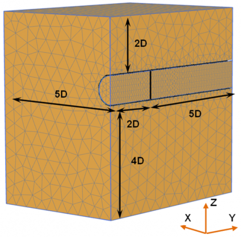
To this end, a deep circular-section tunnel model is adopted to eliminate geometric effects related to tunnel shape. Additionally, to exploit the symmetry of the problem, only half of the model is represented. The tunnel has an outer radius of 5 m, corresponding to a 10 m diameter. The overburden above the tunnel crown is set at 20 m, yielding a cover-to-diameter ratio (C/D) of 2.
To minimize boundary effects, the computational domain dimensions are defined as follows:
• 7D in the longitudinal Y direction (excavation direction),
• 5D in the transverse X direction,
• 4D in the vertical Z direction, between the tunnel invert and the model base.
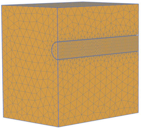
Boundary conditions are applied to restrict displacements: lateral faces are fixed perpendicular to their normal directions, while the bottom face is constrained in all three directions. A triangular mesh is used, consisting of approximately 15,357 elements and 30,081 nodes. To improve the accuracy of deformation calculations, local mesh refinement is applied at the tunnel face, as illustrated in Figure 1.
Figure 1. Adopted mesh and boundary conditions
2.2 Geotechnical properties
The adopted numerical model considers a homogeneous soil mass, represented by a linear elastic-perfectly plastic behavior, defined according to the Mohr-Coulomb failure criterion [25]. The geotechnical parameters characterizing the soil include cohesion (c), internal friction angle (φ), dilatancy angle (ψ), density ($\gamma$), young’s modulus (E), and poisson’s ratio (ν). The material properties of the soil and the lining are presented in Table 1. This numerical study does not account for uncertainty, the spatial variability of strength parameters, or soil heterogeneity, even though these factors can significantly impact the results of geotechnical stability analyses [1, 26-28].
Table 1. Geotechnical properties of the soil mass (Mohr–Coulomb failure criterion)
|
Parameter |
Symbol |
Unit |
Value |
|
Cohesion |
c |
[kPa] |
15 |
|
Friction angle |
φ |
[°] |
30 |
|
Dilatancy angle |
ψ |
[°] |
0 |
|
Density |
$\gamma$ |
[kN/m3] |
21 |
|
Young’s modulus |
E |
[MPa] |
150 |
|
Poisson’s ratio |
ν |
[-] |
0.3 |
2.3 Lateral wall support
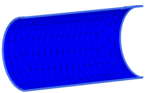
During excavation, a 0.5 m thick support system is installed to ensure the stability of the tunnel’s lateral walls. Its installation is assumed to be immediate and extends across the entire excavated area up to the tunnel face.
In the numerical model, the support system is represented using plate elements, providing a rigid interface with the surrounding soil. This assumption eliminates any deformable interaction between the support and the soil mass, ensuring a more accurate assessment of the reinforcement effect on the tunnel’s response (Figure 2) [29].
Figure 2. Adopted lining and mesh
2.4 Axial fiberglass bolts
Fiberglass bolts exhibit high tensile strength, which contributes to the formation of a reinforced soil core at the tunnel face. Additionally, their inherent brittleness facilitates their destruction during excavation, preventing any interference with the advancement of the works [11, 30, 31].
These bolts have a cross-sectional area of 0.7 × 10⁻³ m² and a length of 15 m. They are installed in 10 cm diameter boreholes, with anchorage ensured by cement grout.
In the numerical modeling, the bolts are considered as linear elastic elements, with a tensile strength limit of 750 kN and an elastic modulus of 86 GPa (Table 2). Although anchorage can provide additional shear and bending resistance, this study only considers pullout resistance, neglecting the effects of bending and shear.
Table 2. Bolt characteristics
|
Parameters |
Symbols |
Units |
Values |
|
Bolt length |
L |
[kPa] |
15 |
|
Borehole diameter |
Ø |
[m] |
0.1 |
|
Elastic modulus |
Eb |
[GPa] |
86 |
|
Tensile strength |
T |
[kN] |
750 |
2.5 Modeling of bolts in Plaxis 3D
In Plaxis 3D, bolts can be modeled using two distinct approaches. The first approach, using "Embedded Beam" elements, represents bolts as integrated beam elements that deform only in tension. This method assumes a perfect bond between the soil and the bolt, without considering the actual mechanical properties of the injection grout.
The second approach, based on a "Pile Interface", provides a more realistic representation of soil-bolt interaction by incorporating key parameters such as anchorage resistance (or bonding strength), shear stiffness, and normal stiffness. It also accounts for bolt density, which influences the distribution of bolts at the tunnel face.
The choice of modeling approach depends on the desired level of accuracy and the assumptions adopted. A detailed analysis of these parameters is presented in the following sections.
2.6 Simulation of construction phasing
Tunnel excavation is a complex process involving three main stages: excavation, support installation, and front-face bolting [32] (Figure 3).
To simplify the numerical modeling, this process is reduced to two key steps:
(1) Stress Initialization: Establishing the initial stress conditions of the soil mass before excavation.
(2) Single-Pass Excavation of 20 m: The entire tunnel is excavated in one phase, with the immediate installation of infinitely rigid support and front-face bolting.
(a) Stress initialization
(b) Tunnel excavation (support + bolts)
Figure 3. Simulation of construction phasing in Plaxis 3D
In the simulation, this final step is represented by deactivating the soil volume in front of the tunnel face, followed by the simultaneous activation of the support and bolts. This approach effectively evaluates the reinforcement's impact on front stability and the displacements induced by excavation.
This parametric study aims to analyze the impact of bolt density and soil-bolt interaction type on tunnel face displacements and the forces developed in the bolts.
3.1 Bolt density at the tunnel face
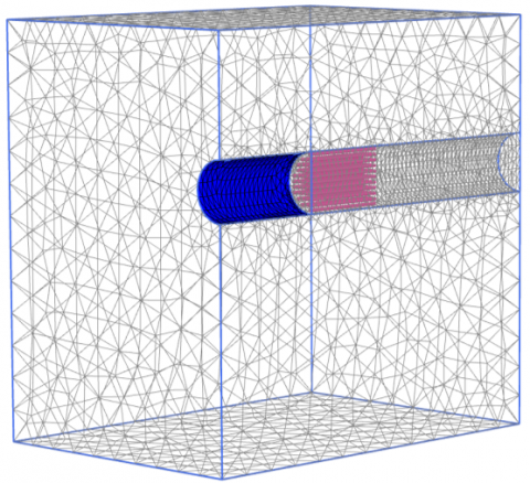
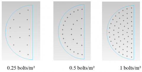
To assess the influence of bolting on tunnel face stability, different bolt densities are considered, ranging from 0 to 1 bolt/m². The selected values for the analysis are 0.0625, 0.125, 0.25, 0.5, and 1 bolt/m², with the reference case corresponding to an unreinforced tunnel face. The adopted bolting configurations are illustrated in Figure 4.
Figure 4. Examples of bolt distribution at the tunnel face for different densities
3.2 Influence of bolting
The tunnel face is the most affected zone during excavation. The displacements induced by excavation can be classified into three main types:
a) Extrusion movement of the tunnel face in the longitudinal direction, parallel to the tunnel axis.
b) Vertical axial displacement (or pre-convergence) behind the tunnel face, along the longitudinal axis passing through the tunnel head.
c) Radial convergence of the excavated section in the transverse direction, perpendicular to the tunnel axis.
In this study, radial convergence is not considered. The tunnel lining is assumed to be infinitely rigid and installed immediately after excavation, which prevents any transverse deformation of the excavated section. This simplification was introduced in order to isolate the effect of longitudinal bolting on face stability without the additional influence of global tunnel deformations. By restricting the analysis to longitudinal displacements, the study ensures that the role of bolting density on face extrusion and pre-convergence can be evaluated more clearly and without secondary effects.
It should be acknowledged, however, that this assumption limits the direct applicability of the results to situations where lining installation is immediate or where transverse deformations are strongly restrained. In cases of delayed lining placement or more deformable support systems, radial convergence may interact with longitudinal deformations, potentially altering the efficiency of reinforcement. Future work should therefore extend the model to account for radial convergence in order to provide a more comprehensive assessment of tunnel behavior.
The present analysis focuses on the impact of bolting density on the axial displacements of the tunnel face, with two main objectives:
• Determine the optimal bolting density, ensuring a balance between deformation reduction and efficient reinforcement use.
• Assess the influence of bolt pullout resistance, emphasizing the importance of accurately estimating this parameter in stability calculations.
In this study, pullout resistance is represented through the embedded length of the bolts and their interaction with the surrounding soil mass. Longer embedded lengths increase the anchorage capacity of the reinforcement and reduce the risk of premature pullout. By explicitly considering variations in embedded length in the parametric study, the influence of pullout resistance on tunnel face stability is indirectly but effectively addressed.
3.3 Tunnel face displacement
The displacement of the tunnel face refers to the horizontal movement of the section located at the excavation front. To assess the effect of bolting, the results obtained for different reinforcement cases are compared by varying the bolting density.
The analyzed cases include:
• An unreinforced tunnel face, modeled using the Mohr-Coulomb soil model.
• A reinforced tunnel face, considering different bolting densities: 0.0625, 0.125, 0.25, 0.5, and 1 bolt/m².
3.4 Influence of bolting density
The effect of bolting density on tunnel face displacement is analyzed by comparing the same reinforcement configurations mentioned above.
The results are illustrated in Figure 5, which presents the evolution of tunnel face displacement as a function of bolting density.
Figure 5. Tunnel face displacement
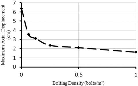
The maximum displacement values are listed in Table 3 and illustrated in Figure 6. Table 4 and Figure 7 present the effectiveness of reinforcement by quantifying the displacement reduction compared to the unreinforced case, expressed as a percentage.
Table 3. Maximum displacement at the tunnel face for two adhesion conditions: perfect and limited
|
Bolting Density (bolts/m²) |
Maximum Displacement at the Tunnel Face (cm) |
|
Unreinforced case |
6.375 |
|
0.0625 |
3.545 |
|
0.125 |
3.104 |
|
0.25 |
2.364 |
|
0.5 |
2.113 |
|
1 |
1.617 |
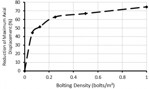
Table 4. Maximum displacement reduction
|
Bolting Density (bolts/m²) |
Maximum Displacement Reduction at the Tunnel Face (%) (Compared to the Unreinforced Case) |
|
0.0625 |
44.40 |
|
0.125 |
51.31 |
|
0.25 |
62.92 |
|
0.5 |
66.86 |
|
1 |
74.64 |
Figure 6. Maximum tunnel face displacement as a function of bolting density
Figure 7. Reduction of maximum tunnel face displacement compared to the unreinforced case, as a function of bolting density
As the bolting density increases, the tunnel face displacement decreases, following a nonlinear trend. A critical threshold is observed at a bolting density of 0.25 bolts/m², where displacement reduction reaches approximately 63%.
Beyond 0.25 bolts/m², the reduction in displacement becomes less significant, with only an additional 11% improvement between 0.25 and 1 bolt/m², leading to a total reduction of 74%.
These findings indicate that bolting efficiency gradually decreases beyond 0.25 bolts/m². This study contributes to determining an optimal bolting density, estimated at 0.25 bolts/m², which ensures a balance between deformation reduction and reinforcement quantity.
3.5 Axial displacement of the soil mass behind the tunnel face
The analysis of axial displacement helps evaluate the effect of bolting on the stability of the soil mass located behind the tunnel face. This displacement is observed over a length equivalent to three times the tunnel radius (3R), corresponding to 15 m ahead of the tunnel face.
The studied configurations include:
• An unreinforced tunnel face, modeled with a Mohr-Coulomb soil behavior.
• A reinforced tunnel face, with varying bolting densities of 0.0625, 0.125, 0.25, 0.5, and 1 bolt/m².
3.6 Influence of bolting density
The impact of bolting density on axial displacement is analyzed by comparing the same reinforcement scenarios. The unreinforced tunnel face is used as a reference case to assess the effectiveness of different configurations.
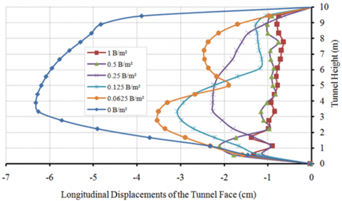
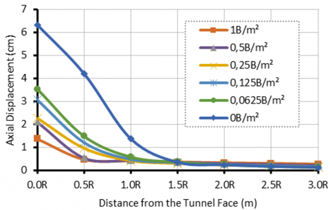
The evolution of axial displacement behind the tunnel face as a function of bolting density is illustrated in Figure 8.
The obtained curves show that beyond a distance of 1R, axial displacements become nearly identical for all bolting densities studied, including the unreinforced case, and completely vanish at a distance of 1.5R. A sudden change in the slope of the deformation curves is observed from 1R, where they become almost horizontal.
This result highlights the extent of the failure zone induced by tunnel excavation, which extends up to 1.5R behind the tunnel face, regardless of the presence of reinforcement. Thus, while bolts reduce the magnitude of axial displacement, they do not alter its extent behind the tunnel face, regardless of the model used.
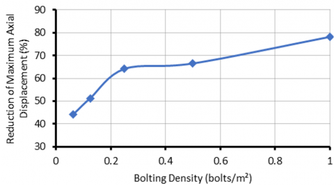
Figure 8 illustrates the maximum axial displacement as a function of bolting density, while Figure 9 presents the percentage reduction of this displacement compared to the unreinforced reference case.
Figure 8. Maximum axial displacement as a function of bolting density
Figure 9. Reduction of maximum axial displacement compared to the unreinforced case as a function of bolting density
Similar to face displacements, the axial displacement curves show a slope change at a critical density, estimated at 0.25 bolts/m². Up to this value, the curve slope remains constant, with an axial displacement reduction of approximately 65%. Beyond 0.25 bolts/m², the additional effectiveness of bolting becomes marginal, with only a 12% improvement. This confirms that 0.25 bolts/m² represents an optimal density, ensuring a good balance between performance and the amount of reinforcement used.
Increasing the bolting density leads to a significant reduction in axial displacement. For instance, a density of 0.0625 bolts/m² reduces the maximum axial displacement by 44%, while a density of 0.25 bolts/m² results in a 65% reduction. At a density of 1 bolt/m², the reduction reaches 78%. These results confirm the effectiveness of bolting in controlling axial displacements, although the improvement becomes marginal beyond 0.25 bolts/m².
Excavation at the tunnel face induces loading and deformation increments in the bolts, revealing a specific behavior depending on their position:
• Near the tunnel face, the bolt acts as a stabilizing element, restraining the surrounding soil. This active load-transfer zone between the soil and the bolt is relatively short but tends to extend as the bond strength limit of the anchorage is reached.
• Beyond this active zone, the bolt anchorage is distributed over a longer length. A transition zone may appear, where the force in the bolt remains nearly constant before gradually decreasing.
• The total loaded length of the bolt corresponds to the soil core zone ahead of the tunnel face, where significant deformations occur. This length is approximately equal to the tunnel diameter.
4.1 Distribution of forces in the bolts
The analysis of force distribution along the bolts is conducted based on their normalized length relative to the tunnel radius (Y/R). Figure 10 illustrates the distribution of forces along a given bolt.
Figure 10. Example of force distribution along a bolt
The initially zero load gradually increases until reaching a maximum value around 0.3R. A sharp decrease follows, marking the anchorage zone, which extends over a length ranging between 0.5R and 2R, depending on the bolting density. Beyond this zone, the forces become negligible as the soil-bolt interaction weakens.
The results also provide insight into the role of pullout resistance in longitudinal bolting. Pullout resistance, which is primarily controlled by the bond between the bolt and surrounding soil, increases with embedded length. As shown in the parametric analysis, longer bolts develop higher axial forces in the anchorage zone (0.5R-2.5R), confirming that sufficient embedment is necessary to fully mobilize reinforcement capacity. Conversely, inadequate embedded length limits pullout resistance, leading to a premature loss of bolt effectiveness. These findings highlight that optimizing bolt density alone is insufficient; ensuring adequate pullout resistance through proper embedment design is equally critical to achieve stable and efficient tunnel face reinforcement.
4.2 Effect of bolting density
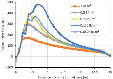
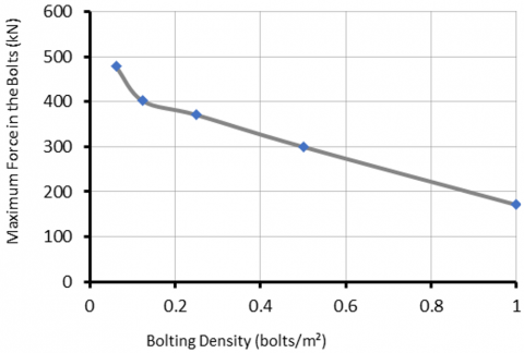
The forces developed in the bolts vary depending on the adopted bolting density. An increase in density modifies the load distribution among the bolts and influences their mechanical demand. Figure 11 illustrates the evolution of maximum forces in the bolts as a function of bolting density.
Figure 11. Maximum forces in the bolts as a function of bolting density
The maximum forces in the bolts increase as the bolting density at the tunnel face decreases. The obtained curve highlights a significant variation in forces for low bolting densities, indicating greater stress on the bolts when their number is reduced. In contrast, for higher densities, the variation in forces becomes more moderate and tends toward a nearly constant value.
These observations contribute to optimizing tunnel face bolting by identifying the density that best mobilizes bolt resistance while minimizing face displacements. To refine this analysis, the extrusion displacements of the tunnel face are correlated with the maximum forces in the bolts, assuming perfect adhesion soil/bolts.
4.3 Calculation of the safety factor for tunnel face stability
The safety factor for tunnel face stability is evaluated using the c-φ reduction method in Plaxis 3D. This approach analyzes the sensitivity of the tunnel face to instability by gradually reducing the soil's cohesion and friction angle until a failure mechanism appears.
The safety factor is calculated for both the unreinforced case and the five studied bolting densities.
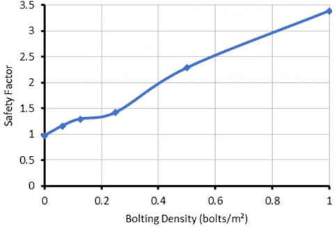
The obtained values are presented in Figure 12, which illustrates the evolution of the safety factor as a function of bolting density. The resulting curve follows a similar trend to that of tunnel face displacements and axial displacements, confirming the consistency of the previously presented results.
Figure 12. Safety factor as a function of bolting density
The safety factor increases by 30% for a bolting density of 0.125 bolts/m² compared to the unreinforced case. The variation in the safety factor as a function of bolting density remains significant, with an increase of approximately 50% for a density of 0.25 bolts/m², reaching an approximate value of 1.5. Beyond this density, the increase in the safety factor remains noticeable, reaching a maximum value of around 3.5. These results highlight the effectiveness of bolting in improving tunnel face stability while also indicating an optimal threshold beyond which additional reinforcement provides diminishing benefits.
This study investigated the influence of tunnel face bolting on the stability of a tunnel in soft ground using a three-dimensional numerical approach. Different bolting densities were analyzed to quantify their impact on tunnel face displacements, bolt forces, and the overall safety factor.
The results demonstrate that bolting significantly reduces tunnel face movements, although it does not entirely prevent soil plasticization. Its effect is more pronounced on global deformations than on axial displacements. The force distribution in the bolts follows a characteristic pattern, consisting of:
• A confinement zone (up to 0.5R), where bolt forces gradually increase to a peak.
• An anchorage zone (0.5R to approximately 2.5R), where forces are distributed over a greater length.
• An inert zone, where bolt forces become negligible.
The analysis revealed that maximum bolt forces correlate with the ultimate bond strength, which defines the limit of force transfer from soil to bolts.
A critical bolting density of 0.25 bolts/m² was identified as the optimal balance between stability improvement and material efficiency. Beyond this threshold, additional reinforcement provides diminishing returns, with only minor improvements in displacement reduction and load distribution.
The safety factor analysis confirmed that bolting enhances tunnel face stability, with a density of 0.25 bolts/m² increasing the safety factor to 1.5, while 1 bolt/m² raises it to 3.5.
These findings contribute to a better understanding of the role of longitudinal bolting in tunnel stabilization and offer practical guidelines for efficient reinforcement strategies. Future research should explore the spatial variability of soil properties, time-dependent effects, and the interaction between bolts and tunnel support systems, further refining design criteria for improved tunnel stability.
[1] Li, B., Hong, Y., Gao, B., Qi, T.Y., et al. (2015). Numerical parametric study on stability and deformation of tunnel face reinforced with face bolts. Tunnelling and Underground Space Technology, 47: 73-80. https://doi.org/10.1016/j.tust.2014.11.008
[2] Di Prisco, C., Flessati, L., Frigerio, G., Castellanza, R., et al. (2018). Experimental investigation of the time-dependent response of unreinforced and reinforced tunnel faces in cohesive soils. Acta Geotechnica, 13(3): 651-670. https://doi.org/10.1007/s11440-017-0573-x
[3] Zhang, X., Wang, M., Lyu, C., Tong, J., et al. (2022). Experimental and numerical study on tunnel faces reinforced by horizontal bolts in sandy ground. Tunnelling and Underground Space Technology, 123: 104412. https://doi.org/10.1016/j.tust.2022.104412
[4] Tian, C., Jiang, Y., Ye, F., Ouyang, A., et al. (2024). Stability analysis of tunnel face reinforced with face bolts. Journal of Mountain Science, 21(7): 2445-2461. https://doi.org/10.1007/s11629-023-8400-3
[5] Zhang, X., Yu, L., Wang, M., Yang, H., et al. (2024). Investigation of the failure mechanism and theoretical model of bolt-reinforced shallow tunnel faces with different bolt lengths. Underground Space, 16: 126-142. https://doi.org/10.1016/j.undsp.2023.10.002
[6] Guo, F., Zhang, N., Feng, X., Xie, Z., et al. (2024). Variations of entries and bolting technologies, a case study based on a field monitoring of a longwall face. Engineering Geology, 331: 107458. https://doi.org/10.1016/j.enggeo.2024.107458
[7] Tan, C.H. (2020). Solution of a bolted spherical cavity in elastoplastic medium and its application to extrusion analysis of tunnel face. Rock Mechanics and Rock Engineering, 53(7): 3055-3072. https://doi.org/10.1007/s00603-020-02086-3
[8] Chen, G.H., Zou, J.F., Xiang, X.Y., Pan, Q.J., Qian, Z.H. (2021). Stability assessments of reinforced tunnel face using improved homogenization approach. International Journal of Geomechanics, 21(10): 04021183. https://doi.org/10.1061/(asce)gm.1943-5622.0002153
[9] Wang, M., Shang, L., Zhang, B., Li, Y., et al. (2023). Study on reasonable anchorage length based on failure mechanism of the bolt anchorage system. Scientific Reports, 13(1): 22915. https://doi.org/10.1038/s41598-023-45778-w
[10] Cai, Y., Esaki, T., Jiang, Y. (2004). An analytical model to predict axial load in grouted rock bolt for soft rock tunnelling. Tunnelling and underground space technology, 19(6): 607-618. https://doi.org/10.1016/j.tust.2004.02.129
[11] Li, H., Fu, J., Chen, B., Zhang, X., et al. (2023). Mechanical properties of GFRP bolts and its application in tunnel face reinforcement. Materials, 16(6): 2193. https://doi.org/10.3390/ma16062193
[12] Bastick, M., Dubois, B., Frank, R., Gigan, J.P., et al. (2002). Additif 2002 aux recommandations CLOUTERRE 1991 pour le calcul, l'exécution et le contrôle des soutènements réalisés par clouage des sols. Presses de l'Ecole nationale des ponts et chaussées, 217. https://enpc.hal.science/hal-00853397v1.
[13] Sun, Z., Zhang, D., Li, A., Lu, S., et al. (2022). Model test and numerical analysis for the face failure mechanism of large cross-section tunnels under different ground conditions. Tunnelling and Underground Space Technology, 130: 104735. https://doi.org/10.1016/j.tust.2022.104735
[14] Chen, J., Che, Z., Song, Q., Song, W., et al. (2024). Comparative analysis and application of a new stability model for the tunnel face with Mogi-coulomb criterion. Geomechanics and Geophysics for Geo-Energy and Geo-Resources, 10(1): 193. https://doi.org/10.1007/s40948-024-00914-2
[15] Lunardi, P., Bindi, R., Cassani, G. (2014). The reinforcement of the core face: History and state of the art of the Italian technology that has revolutionized the world of tunneling. Some reflections. In Proceedings of the world tunnel congress. https://www.rocksoil.com/pdf/235_r.pdf.
[16] Cui, X., Li, P., Ge, Z., Li, S., Chen, Y. (2025). Experimental study on face stability of shield tunnel in water-rich inclined composite strata considering different inclination angles. Applied Ocean Research, 154: 104323. https://doi.org/10.1016/j.apor.2024.104323
[17] Serratrice, J.F., Magnan, J.P. (2002). Analyse et prévision des tassements de surface pendant le creusement du tunnel nord de la traversée souterraine de Toulon. Bulletin des Laboratoires des Ponts et Chaussées, 237: 5-36. https://www.ifsttar.fr/collections/BLPCpdfs/blpc_237_5-36.pdf.
[18] Guilloux, A., Le Bissonnai, H. (2016). Settlement management for urban tunnels: An example from France. Geotechnical Engineering Journal of the SEAGS & AGSSEA, 47(1): 118-125. https://doi.org/10.14456/seagj.2016.67
[19] Varnusfaderani, M.G., Golshani, A., Nemati, R. (2015). Behavior of circular tunnels crossing active faults. Acta Geodynamica et Geromaterialia, 12(4): 363-377. https://doi.org/10.13168/agg.2015.0039
[20] Naghadehi, M.Z., Thewes, M., Lavasan, A.A. (2019). Face stability analysis of mechanized shield tunneling: An objective systems approach to the problem. Engineering Geology, 262: 105307. https://doi.org/10.1016/j.enggeo.2019.105307
[21] Mandel, J. (1962). Essais sur modèles réduits en mécanique des terrains. Etude des conditions de similitude. Société Nouvelle des Imprimeries de la Loire Républicaine.
[22] Dias, D., Janin, J.P., Soubra, A.H., Kastner, R. (2008). Three-dimensional face stability analysis of circular tunnels by numerical simulations. In GeoCongress 2008: Characterization, Monitoring, and Modeling of GeoSystems, New Orleans, Louisiana, pp. 886-893. https://doi.org/10.1061/40972(311)111
[23] Hong, Y., Soomro, M.A., Ng, C.W.W. (2015). Settlement and load transfer mechanism of pile group due to side-by-side twin tunnelling. Computers and Geotechnics, 64: 105-119. https://doi.org/10.1016/j.compgeo.2014.10.007
[24] Cheng, C., Ni, P., Zhao, W., Jia, P., et al. (2021). Face stability analysis of EPB shield tunnel in dense sand stratum considering the evolution of failure pattern. Computers and Geotechnics, 130: 103890. https://doi.org/10.1016/j.compgeo.2020.103890
[25] Varnusfaderani, M.G., Golshani, A., Majidian, S. (2017). Analysis of cylindrical tunnels under combined primary near fault seismic excitations and subsequent reverse fault rupture. Acta Geodynamica et Geomaterialia, 14(1): 5-26. https://doi.org/10.13168/agg.2016.0024
[26] Wang, L.Z., Wang, Z., Li, L.L., Wang, J.C. (2011). Construction behavior simulation of a hydraulic tunnel during standpipe lifting. Tunnelling and underground space technology, 26(6): 674-685. https://doi.org/10.1016/j.tust.2011.05.009
[27] Jiang, S.H., Li, D.Q., Zhang, L.M., Zhou, C.B. (2014). Slope reliability analysis considering spatially variable shear strength parameters using a non-intrusive stochastic finite element method. Engineering Geology, 168: 120-128. https://doi.org/10.1016/j.enggeo.2013.11.006
[28] Hou, C., Zhong, J., Yang, X. (2023). Three-dimensional stability assessments of a non-circular tunnel face reinforced by bolts under seepage flow conditions. Tunnelling and Underground Space Technology, 131: 104831. https://doi.org/10.1016/j.tust.2022.104831
[29] Cai, W., Zhu, H., Liang, W. (2022). Three-dimensional tunnel face extrusion and reinforcement effects of underground excavations in deep rock masses. International Journal of Rock Mechanics and Mining Sciences, 150: 104999. https://doi.org/10.1016/j.ijrmms.2021.104999
[30] Georgiou, D., Kavvadas, M., Kalos, A. (2021). Numerical investigation of tunnel face sability using forepoling or fiberglass nails. https://doi.org/10.21203/rs.3.rs-509665/v1
[31] Paternesi, A., Schweiger, H.F., Scarpelli, G. (2017). Numerical analyses of stability and deformation behavior of reinforced and unreinforced tunnel faces. Computers and Geotechnics, 88: 256-266. https://doi.org/10.1016/j.compgeo.2017.04.002
[32] Su, K., Zhang, Y.J., Cui, J.P., Li, C.A. (2020). Installation time of ground support during tunnel excavation: A novel graph methodology. KSCE Journal of Civil Engineering, 24(12): 3866-3874. https://doi.org/10.1007/s12205-020-1079-x