Iltifat Lazim Edan![]() | Mohammed Jameel Alsalhy
| Mohammed Jameel Alsalhy![]() | Baydaa Adnan Hussein
| Baydaa Adnan Hussein![]() | Ahmed A. Ouda*
| Ahmed A. Ouda*![]()
© 2025 The authors. This article is published by IIETA and is licensed under the CC BY 4.0 license (http://creativecommons.org/licenses/by/4.0/).
OPEN ACCESS
This study presents the numerical study of three dimensional turbulent flow and heat transfer in a U-shaped tube with a twist tape insert operating under a constant heat flux condition. Under the Reynolds number range of 5000 to 25000, the value of the twisting ratio (y/w) of 5 is studied in water with various cross-section shapes (ellipse, triangular, and circular) and a constant cross-section area. The RNG k-ε turbulence model was used for turbulent flow. The purpose of this study is to improve heat transfer in a tube by combining the effects of twisted tape with a U-shaped tube. In the U-tube with the tapes, the numerical results demonstrate that the twisted tapes and the bend section create multi-swirling flow, which promote fluid mixing and improve the heat transfer rate. When comparing the U-tube with a circular cross-section to one with an elliptical one, the mean Nusselt for the triangle cross-section was 13.8 percent and 16.6 percent, respectively; this represents a significant reduction in the friction factor. A considerable improvement in heat transport is seen within the triangle cross-section U-tube, according to numerical investigations.
U-tube, twist ratio, twisted tape, heat transfer enhancement
Heat exchangers have many commercial and industrial uses, such as petrochemical, chemical processes, heat generation and recovery systems [1, 2]. The principle of heat exchangers is utilized to enable heat transfer between cold fluid and hot fluid streams. Thermal energy between walls of heat exchanger depends on the transfer mechanism from cold fluid to hot fluid [3]. There are passive and active techniques that use to enhance the efficiency of heat transfer. The active method requires external power to apply, while the passive technique depends on the geometry modification [4].
There are many researchers in literature who studied the performance of the heat exchanger with a U–tube configuration, such as the authors Yu et al. [5] who investigated the flow and heat transfer parameters using numerical simulation for tubes with Reynolds numbers between 4000 and 16,000. The ellipse ratio r may be anywhere from 1.2 to 2, and the twist pitch p can be anywhere from 0.02 to 0.10 m. Channel depth e for a two-start twist tube is between 0.4 and 2 mm. The results revealed that the comparative friction coefficient and Nusselt number improved with the ellipse ratio (r) and dropped with the twist pitch (p) for twisting oval helically looped tubing. Compared to the twist oval helically wrapped tube, the average TEF of the two-start twist was much greater.
Bhattacharyya and Saha [6] studied investigational friction factor and Nusselt number data have been given. For laminar flow over a circular duct with integrated helical ribs for roughness and fitted with twist-tapes center cleared. A circular acrylic conduit with an inside diameter of 13 mm and a length of 2 m was used to measure the pressure decrease. They also show that there is a link between the predictive friction factor and the Nusselt number. They analyzed the thermos-hydraulic performance. These experimental results showed that, up to a certain quantity of twist-tapes center-clearance, laminar flow can be maintained through a circular duct more effectively using a combination of center-cleared twisted tapes and integral helical ribs roughness than using either enhancement technique separately. Rezaei Gorjaei and Shahidian [7] discussed improving heat transmission in the bent tube; the researchers here experimented with both twist tape inserts and nanofluid turbulent flow (passive approaches). Copper is shaped into a tube with a bend and a twist tapes. A pool of hot water is used to conduct the experiment, with the test portion (curved tube) immersed within. The water/Al2O3 nanofluid is made using a three-stage process. Convective heat transfer coefficient, Nusselt numbers, and Darcy friction factor are investigated as a function of volume flow rate, nanoparticle concentrations, and twist tapes insert. They demonstrated that the use of a curved tube with twisted tape inserts can enhance convective heat transfer by up to 31%. Furthermore, the convective heat transfer coefficient was reported to increase by approximately 21% when the concentration of Al₂O₃ nanoparticles was raised from 0% to 1%. Mahdi et al. [8] investigated the heat transfer performance of a single-tube heat exchanger, comparing cases with and without twisted tape inserts (y/w = 4 and 6). The test section was made of copper, measuring 1 m in length, with an inner diameter of 23 mm and an outer diameter of 25 mm. Below laminar flow conditions (Re =1056 - 2002), distilled water flows over a tube insulated with fibers glass on the outside to prevent heat loss. The copper tape used was 0.8 mm thick and ran the whole length of the test area. Compared to using a smooth tube, the use of insert tape increased the heat transmission coefficient by an impressive 16–27%. They found that empirical relationships between the Nusselt number and the friction factor were established. The flow fields and heat transport are analyzed and simulated using ANSYS 15.0, FLUENT software. Abdul Razzaq and Mushatet [9] presented the growing relevance of heat exchangers across a variety of sectors has led to a rise in research and development efforts focused on improving heat transfer, boosting overall performance, minimizing size and cost. The double-pipe heat exchanger is a vital piece of equipment in several industries. Tube-shaped heat exchanger. Passive, active, and hybrid tactics, as well as a few others, have all been used to effect change. One of the most efficient ways to boost thermal efficiency. Overall heat performance. More importantly, increasing heat transmission as nanofluids entails several strategies, one of the most imperative of which is the hybridization of flow liquids. The development of heat exchangers and strategies for enhancing passive heat transfer are surveyed and analyzed in this article. Secondary eddy flow was also explored, which enhances the intensity of turbulence and mixings and improves heat transfer in a number of twisted heat exchanger tube forms (oval, square, and triangular). Substances added to heat exchanger tube. structure with conical ring, ribs, and twisted tape. Rubbi et al. [10] explained in this study approved out for the turbulent flow regime (4000 ≤ Re ≤ 10000) at a twist ratios of 4.0 by means of ANSYS fluent. Boundary conditions and the main equations for the turbulent models are applied to the mathematical model of a flow domain that has been previously constructed. They found from achieved numerical results reveal that increases heat transmission by up to 69.4 percent related to a plains tube because to enhanced mixing and efficient swirl movement. A corresponding rise in friction factor over plain tube is seen. At constant pumping power, the influence on the thermal performance factor has reached a maximum of 1.24 for Reynolds number 4000. Khudheyer and Ayad Ali [11] discussed the effects of the U-tube's cross-section form on the temperature and flow rate are discoursed in depth. The U-tube is put through its paces by employing tubes of various cross-section forms (square and rectangle) and comparing them to a circular tube with the same cross-section area and curvature radius ratio with a fluctuating Reynolds number (10000-25000) corresponding to a turbulent flow. They obtained results when related to a U-tube with a circular cross section (of the same area), the Nusselt number is reduced by 21.6% when using a square or rectangular cross section, and the friction factor is reduced by 7.4% when using a rectangular cross section. Yang et al. [12] described the effect of tubes structural characteristics (aspects ratio and twists pitch) on the performance of TETs were examined and the overall thermal-hydraulics performance of TETs was assessed. The TETs were shown to significantly improve heat transmission and create a large pressure drop within the tube during experiments. Both the heat transfer coefficients and the friction factor improved when the aspect ratio of the tube was improved and the twist pitch was reduced. TETs thrive in environments with low Reynolds numbers. It was also revealed that the investigational Nusselt number and friction factors can be described using one integrated equation over full Reynolds numbers ranges, which validates the primary flow transitions from laminar to turbulent in TETs.
Recent studies continue to show strong thermo-hydraulic gains when swirl-inducing inserts or twisted/noncircular tubes are used in double-pipe and U-tube geometries. For example, perforated or profiled twisted-tape variants and other rod-type turbulators can raise Nusselt number substantially with acceptable friction penalties, and multi-objective optimization is increasingly used to balance heat transfer vs. pressure drop [13-16]. In parallel, twisted elliptical/oval tubes—alone or combined with twisted-tape inserts are drawing attention for delivering high performance evaluation criteria (PEC > 1) across laminar–turbulent regimes [17-19]. Very recent parametric and review works also benchmark alternate twist directions, phase angles, and ribbed/slot patterns, and recommend turbulence-model choices for CFD on spiral/coiled or twisted-tube flow [14, 18, 20]. These trends align with our approach and support the relevance of our geometry and modeling choices.
The aim of the present research introduces an analysis of the thermal performance of U-tubes with insert twist tape and various cross-sections. The outcomes produced by the suggested model are compared to those of conventional U-tubes in a thorough investigation. When studying thermal performance, the Nusselt number is an important metric to consider. Researching how modifying the U-tube's cross-section affects the flow field, friction, and heat transfer enhancement.
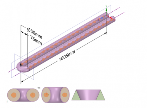
The configuration of the U-tube comprises three components: The downstream tube, the U-bend, and the upstream tube. This study employs many cross-sections, including circular cross-sectional U-tubes (CUT), elliptical cross-sectional U-tubes (EUT), and triangular cross-sectional U-tubes (TUT), as illustrated in Figure 1. The working fluid is water, flowing through the tube at a changeable velocity and inlet temperature. The length of the upstream and downstream sections of the tube is 1 meter, with a curvature radius of 0.75 meters. The twisted tape and wall thickness measure 5 mm. In (CUT), the tube diameter is 50 mm; in (EUT), the main diameter is 71.2 mm and the minor diameter is 35.2 mm; in (TUT), the length of the equilateral triangle is 43.13 mm. The pitch of the twisted tape measures 100 mm.
Figure 1. The geometry of U-tube of different shapes inserted with twisted tapes
3.1 Assumptions
In numerical solving, use the assumptions below to simplify the model proposed [21-24]:
1. Water use as working fluid at constant properties.
2. The flow is steady state.
3. The flow is incompressible and non-slip.
4. The thickness of the wall is negligible.
3.2 Governing equations
The governing equations used to describe of turbulent flow benefits from decomposing it into mean motions and fluctuations or eddy motions [25, 26]:
Continuity equation:
$\frac{\partial \rho u}{\partial x}+\frac{\partial \rho v}{\partial y}+\frac{\partial \rho w}{\partial z}=0$ (1)
Momentum equation in the x-direction:
$\begin{aligned}\left(\frac{\partial u^2}{\partial \mathrm{x}}+\frac{\partial \mathrm{u} v}{\partial \mathrm{y}}+\frac{\partial \mathrm{uw}}{\partial \mathrm{z}}\right) & =-\frac{1}{\rho} \frac{\partial \mathrm{P}}{\partial \mathrm{x}}+\frac{\partial}{\partial \mathrm{x}}\left(2 \mu_{e f f} \frac{\partial \mathrm{u}}{\partial \mathrm{x}}\right) \\ & +\frac{\partial}{\partial \mathrm{y}}\left(\mu_{e f f} \frac{\partial \mathrm{u}}{\partial \mathrm{y}}\right)+\frac{\partial}{\partial \mathrm{z}}\left(\mu_{e f f} \frac{\partial \mathrm{u}}{\partial \mathrm{z}}\right) \\ & +\frac{\partial}{\partial \mathrm{y}}\left(\mu_{e f f} \frac{\partial v}{\partial \mathrm{x}}\right)+\frac{\partial}{\partial \mathrm{z}}\left(\mu_{e f f} \frac{\partial \mathrm{w}}{\partial \mathrm{x}}\right)\end{aligned}$ (2)
Momentum equation in the y-direction:
$\begin{aligned}\left(\frac{\partial v \mathrm{u}}{\partial \mathrm{x}}+\frac{\partial v^2}{\partial \mathrm{y}}+\frac{\partial v \mathrm{w}}{\partial \mathrm{z}}\right) & =-\frac{1}{\rho} \frac{\partial \mathrm{P}}{\partial \mathrm{x}}+\frac{\partial}{\partial \mathrm{x}}\left(\mu_{e f f} \frac{\partial v}{\partial \mathrm{x}}\right) \\ & +\frac{\partial}{\partial \mathrm{y}}\left(2 \mu_{e f f} \frac{\partial v}{\partial \mathrm{y}}\right)+\frac{\partial}{\partial \mathrm{z}}\left(\mu_{e f f} \frac{\partial v}{\partial \mathrm{z}}\right) \\ & +\frac{\partial}{\partial \mathrm{x}}\left(\mu_{e f f} \frac{\partial \mathrm{u}}{\partial \mathrm{y}}\right)+\frac{\partial}{\partial \mathrm{z}}\left(\mu_{e f f} \frac{\partial \mathrm{w}}{\partial \mathrm{y}}\right)\end{aligned}$ (3)
Momentum equation in the z-direction:
$\begin{aligned} & \left(\frac{\partial \mathrm{wu}}{\partial \mathrm{x}}+\frac{\partial \mathrm{w} v}{\partial \mathrm{y}}+\frac{\partial w^2}{\partial \mathrm{z}}\right) \\ & \quad=-\frac{1}{\rho} \frac{\partial \mathrm{P}}{\partial \mathrm{x}}+\frac{\partial}{\partial \mathrm{x}}\left(\mu_{e f f} \frac{\partial \mathrm{w}}{\partial \mathrm{x}}\right) \\ & \quad+\frac{\partial}{\partial \mathrm{y}}\left(\mu_{e f f} \frac{\partial \mathrm{w}}{\partial \mathrm{y}}\right)+\frac{\partial}{\partial \mathrm{z}}\left(2 \mu_{e f f} \frac{\partial \mathrm{w}}{\partial \mathrm{z}}\right) \\ & \quad+\frac{\partial}{\partial \mathrm{x}}\left(\mu_{e f f} \frac{\partial \mathrm{u}}{\partial \mathrm{z}}\right)+\frac{\partial}{\partial \mathrm{y}}\left(\mu_{e f f} \frac{\partial v}{\partial \mathrm{z}}\right)\end{aligned}$ (4)
Energy equation:
$\begin{aligned} & \frac{\partial \boldsymbol{u} \mathrm{T}}{\partial \mathrm{x}}+\frac{\partial \boldsymbol{v} \mathrm{T}}{\partial \mathrm{y}}+\frac{\partial \boldsymbol{w} \mathrm{T}}{\partial \mathrm{z}} \\ & =\frac{\partial}{\partial \mathrm{x}}\left(\Gamma_{e f f} \frac{\partial \mathrm{~T}}{\partial \mathrm{x}}\right)+\frac{\partial}{\partial \mathrm{y}}\left(\Gamma_{e f f} \frac{\partial \mathrm{~T}}{\partial \mathrm{y}}\right) \\ & +\frac{\partial}{\partial \mathrm{z}}\left(\Gamma_{e f f} \frac{\partial \mathrm{~T}}{\partial \mathrm{z}}\right)\end{aligned}$ (5)
To simulate the k- Ԑmodel use Eq. (6) for turbulent kinetic energy (k) [14, 27, 28]:
$\begin{aligned} \rho\left(\frac{\partial}{\partial x}(k u)+\frac{\partial}{\partial y}\right. & \left.(k v)+\frac{\partial}{\partial z}(k w)\right) \\ & =\frac{\partial}{\partial x}\left(\frac{\mu_t}{\sigma_k} \frac{\partial k}{\partial x}\right)+\frac{\partial}{\partial y}\left(\frac{\mu_t}{\sigma_k} \frac{\partial k}{\partial y}\right) \\ & +\frac{\partial}{\partial z}\left(\frac{\mu_t}{\sigma_k} \frac{\partial k}{\partial z}\right)+G-\rho \varepsilon\end{aligned}$ (6)
For energy dissipation rate (Ԑ):
$\begin{aligned} \rho\left(\frac{\partial}{\partial x}(\varepsilon u)\right. & \left.+\frac{\partial}{\partial y}(\varepsilon v)+\frac{\partial}{\partial z}(\varepsilon w)\right) \\ = & \frac{\partial}{\partial x}\left(\frac{\mu_t}{\sigma_{\varepsilon}} \frac{\partial \varepsilon}{\partial x}\right)+\frac{\partial}{\partial y}\left(\frac{\mu_t}{\sigma_{\varepsilon}} \frac{\partial \varepsilon}{\partial y}\right) \\ & +\frac{\partial}{\partial z}\left(\frac{\mu_t}{\sigma_{\varepsilon}} \frac{\partial \varepsilon}{\partial z}\right)+C_{1 \varepsilon} \rho \frac{\varepsilon}{k} G-C_{2 \varepsilon} \rho \frac{\varepsilon^2}{k}\end{aligned}$ (7)
The generation term is denoted by G and is provided in [12, 27]:
$\begin{aligned} \mathrm{G}=\mu_{\mathrm{t}}\left[2\left(\frac{\partial \mathrm{u}}{\partial \mathrm{x}}\right)^2\right. & +2\left(\frac{\partial \mathrm{v}}{\partial \mathrm{y}}\right)^2+2\left(\frac{\partial \mathrm{w}}{\partial \mathrm{z}}\right)^2+\left(\frac{\partial \mathrm{v}}{\partial \mathrm{y}} \frac{\partial \mathrm{u}}{\partial \mathrm{x}}\right)^2 \\ & \left.+\left(\frac{\partial \mathrm{v}}{\partial \mathrm{z}} \frac{\partial \mathrm{w}}{\partial \mathrm{x}}\right)^2+\left(\frac{\partial \mathrm{v}}{\partial \mathrm{z}} \frac{\partial \mathrm{w}}{\partial \mathrm{y}}\right)^2\right]\end{aligned}$ (8)
To calculate Re that represents the ratio of inertia force to viscous force.
$R e=\frac{\rho \operatorname{Dh} u}{\mu}$ (9)
$D h=d i$ (10)
The Nusselt numbers is given as:
$\mathrm{Nu}=\frac{\mathrm{h} \mathrm{D}_{\mathrm{h}}}{\mathrm{K}_{\mathrm{f}}}$ (11)
$\mathrm{h}=\frac{\mathrm{m}_{\mathrm{h}} \mathrm{cp}_{\mathrm{h}}\left(\mathrm{T}_{\mathrm{i}}-\mathrm{T}_{\mathrm{o}}\right)}{\mathrm{A}_{\mathrm{s}, \mathrm{i}}\left(\mathrm{T}_{\mathrm{m}}-\mathrm{T}_{\mathrm{s}}\right)}$ (12)
$F=\frac{2 D \Delta P}{\rho L u^2}$ (13)
where, Tw is the wall temperature and Tm is the bulk temperature of the fluid.
The friction factor and Reynolds number relation was validated against established empirical correlations. For smooth tubes, the Ouda equation was employed for comparison. Their work provides a refined expression for f–Re suitable for flow conditions, allowing more accurate benchmarking of the present triangular cross-section simulations.
The numerical calculations are executed by resolving momentum, continuity, and energy equations. With ANSYS Workbench 18.2, you may access the CFD 18.2 solver that is founded on the finite volume approach. Specifically, the suggested SST k-e models are used in the turbulent regime. The field known as computational fluid dynamics (CFD) studies how to use computers to quantitatively calculate the basis of fluid flow. The principles of fluid mechanics and conservation of energy are part of this, as are the tools that will form the backbone of the engineering application's design and development. As a result of its use in predicting interior flow and the advent of computers that are more accurate and closer to the truth, computational fluid dynamics (CFD) has become an essential part of the work of many academics across the world [27, 29].
4.1 Boundary condition
1- Conditions at the entrance
U = Uin, the uniform inlet velocity. It's an isothermal flow (T = Tin = 300 K).
2- The velocity at the walls is assumed to be zero (no slip), which is the second condition of the wall boundary. along the x, y, and z axes, with u = v = w = 0. A constant heat flux defined as 1000W/m.
3- The third condition is the outlet boundary, which states that the gauge pressure must be zero at the exit domain.
4.2 Mesh grid
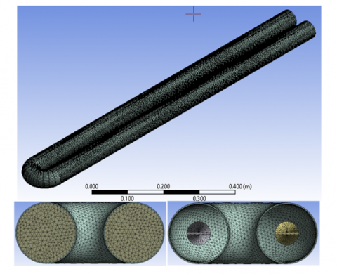
In numerical investigation, the mesh independence is very important; therefore, the selection of a better grid gets a better solution. Tetrahedral element type of mesh used in this study the details and a magnification of the mesh grid are explained in Figure 2.
Figure 2. The mesh grid for the circular U-tubes
In order to describe the turbulent state fluid motion in the tube, one must solve not only the (k-e) model equation but also the regular differential equations of mass (continuity) and momentum. The fluctuation velocity field is a defining feature of turbulent flow.
4.3 Validation of numerical results
The computed Nusselt numbers and friction factors were validated against widely used smooth-tube correlations. For the smooth-tube baselines the Ouda et al. [28] explicit formula (for Darcy friction factor, hydraulically smooth walls) and the Gnielinski correlation (turbulent heat transfer) were used. The hydraulic diameter Dh = 0.05 m and water properties at 300 K (Pr ≈ 6.9) were employed in the comparisons.
Using these correlations the baseline values NuGn and fH were computed and compared with the model predictions for the triangular cross-section. The triangular geometry increases corner-driven secondary flow and the wetted perimeter (smaller Dh for the same area), which explains the systematic enhancement of Nu and the concurrent increase of f. For the illustrative case shown below (triangle Nu ≈ 13.8% above the smooth-tube baseline and f ≈ 20% above the baseline due to corner/shear effects) the performance evaluation criterion (PEC) was computed as
$P E C=\frac{N u / N u_0}{\left(f / f_0\right)^{1 / 3}}$ (14)
A PEC larger than unity indicates a net benefit in heat-transfer performance relative to the pressure-loss penalty. The illustrative results give PEC ≈ 1.07 across the studied Reynolds numbers, confirming that the triangular cross-section with the chosen twisted-tape configuration provides a favorable trade-off between heat transfer enhancement and pumping power penalty. A quantitative comparison table is given in Table 1.
Table 1. Comparison between empirical and numerical Nu and f
|
Re |
f |
f_Ouda |
Nu |
Nu_Gnielinski |
|
5,000 |
0.04527 |
0.03772 |
45.05 |
39.60 |
|
15,000 |
0.03324 |
0.02770 |
128.49 |
112.95 |
|
25,000 |
0.02924 |
0.02437 |
202.22 |
177.77 |
To confirm the increase of forced convections in a U-tube design with various forms, this section addresses the numerical results. For the circular, elliptical, and triangular cross-sections of the U-tubes, the hydraulic diameter is 0.05 m, correspondingly. This article discusses studded instances for U-tubes that have the same cross-section area as circular U-tubes but have various cross-section shapes (ellipse, triangle).
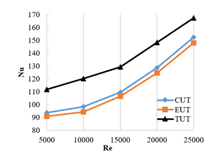
Figure 3. Consequence of cross-section shapes and twist tape on Nusselt number for U-tube
Figure 3 displays the impact of the cross-section shape on the average difference of the Nusselt number for various Reynolds numbers. For all cross-section forms, the Nusselt number grows with the Reynolds numbers as a result of increasing fluid turbulence. The growth in the Nusselt number and the strength of secondary flow are both caused by the increased turbulence caused by twist tape. When comparing the triangle cross-section shape to the elliptic U-tube, the maximum Nusselt number values are shown for the former. The results showed that when comparing the U-tubes with different cross-sections, the mean Nusselt for the triangle cross-section was 13.8% with the circular cross-section, and 16.6%with the elliptical cross-section. In terms of heat transfer, the triangle tube is optimal, but it also has the greatest pressure drop.
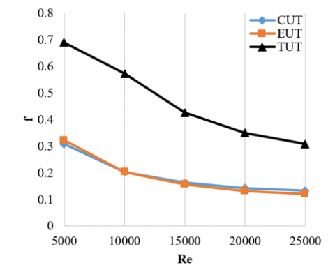
Figure 4 displays the effect of the cross-section shapes on the average difference in the friction factor for various values of the Reynolds numbers. With rising Reynolds numbers, the friction factors obtained from elliptical and circular cross-sections decrease. Based on the figure, it is clear that using U-tubes with circular or elliptic cross-sections reduce the friction factor, whereas using U-tubes with triangular cross-sections causes the friction factor to significantly increase for the same cross-section area. According to the data, the friction factor is determined to be higher for the U-tube with a triangular cross section compared to the circular and elliptical cross-sections. Using the U-bend arrangement with twist tape increases the friction factor for all the cross-section configurations that were studied. The reason behind this is the significant wall shear stress at the bend section and twisting tape.
Figure 4. Consequence of cross-section shapes and twist tape on friction factor for U-tube
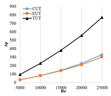
For various values of the Reynolds number, Figure 5 shows how the cross-section shape affects the variance of the pressure drop. Pressure losses measured using elliptical and circular cross-sections are found to grow as the Reynolds number increases. The greatest increase in pressure drops was observed in U-tubes with a triangular cross section, as compared to those with an elliptical or circular cross-section. The data showed that the pressure loss was higher for the U-tube with a triangular cross-section compared to the ones with an ellipse or circular cross-section. The turbulence is increased by twist tape, and the resistance to flow is increased by generating secondary flow, which dissipates kinetic energy. Using twist tape in a U-bend design obviously increases pressure loss. This is due to the fact that the U-tube has a longer length and more twists than a straight tube, which results in a higher reverse flow generation.
Figure 5. Consequence of cross-section shapes and twist tape on pressure drops for U-tube
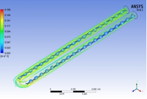
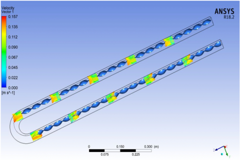
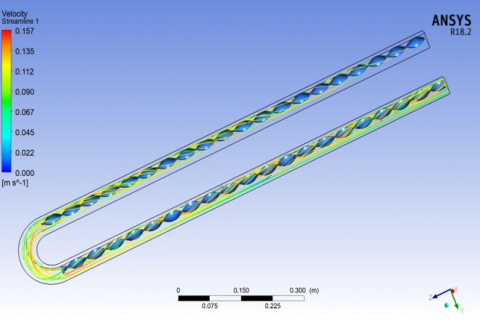
Figure 6. Velocity vector and streamline for u- tube for Re = 5000 of the circular U-tube
In this section, we will analyze the numerical findings for flow inside a heated U-tube formation with various preparations and cross-section forms. This will help us understand the flow and thermal attitude that impact as shown in Figures 6-8; the velocity vectors for the U-tube case and the impact of the variation in cross-section shapes on water flowing with Re = 5000 are displayed. As fluid moves away from the tube wall and towards its center, the upstream tube domain flow velocity increases for all cross-section forms, eventually reaching its maximum value at the center. For the circular, elliptical, and triangular U-tubes, the corresponding velocity vectors are shown in Figures 6-8. As the fluid moves outward from the tube’s center and towards its walls, the twisted band causes secondary flow, which causes vortices and more turbulence. The tangential velocity increases, and eddy flow is created when the fluid approaches the U-bend region. When viewed via the bend at a right angle to the present model, the highest transverse velocity.
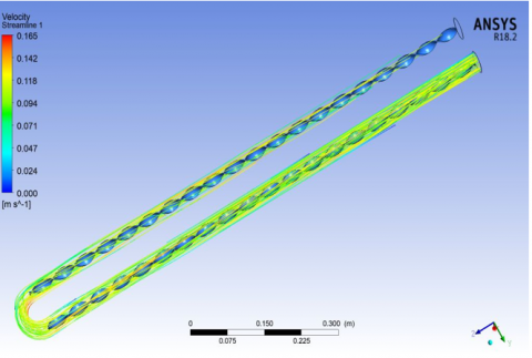
Figure 7. Velocity vector and streamline for u- tube for Re = 5000 of the ellipse u-tube
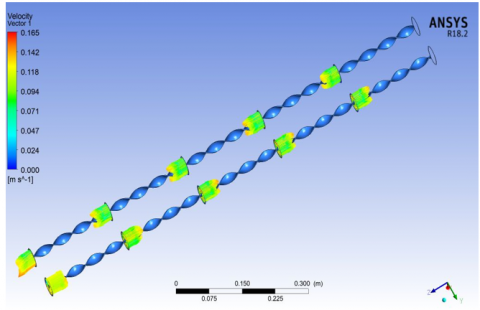
Figure 8. Velocity vector and streamline for u- tube for Re = 5000 of the triangle U-tube
The superior thermal performance of the triangular cross-section U-tube can be attributed to two main factors. First, the triangular geometry introduces sharp corners that generate localized secondary vortices, intensifying mixing between core and near-wall fluid layers. This improves convective heat transfer by reducing the thermal boundary layer thickness. Second, for a constant cross-sectional area, the triangular shape has a larger wetted perimeter compared to the circular or elliptical tubes. The increased heat transfer surface area per unit flow cross-section enhances the Nusselt number, although it also raises wall shear stress and, consequently, the friction factor.
Importantly, the performance evaluation criterion (PEC) exceeded unity across the Reynolds number range, confirming that the triangular cross-section delivers a net thermal advantage despite the frictional penalty. The agreement with empirical smooth-tube correlations validates the numerical approach and supports the conclusion that triangular cross-sections with twisted tape inserts provide a promising passive technique for compact heat exchanger design.
Numerical investigations were conducted to analyze the heat transfer, friction losses, and thermal performance features of a U-tube design with different configurations of twisted tape at a twist ratio of 5. The study focused on Reynolds numbers ranging from 5000 to 25000, specifically for turbulent flow. The following deductions can be made.
1. A numerical investigation was conducted to evaluate heat transfer and fluid flow in a triangular cross-section tube with double twisted tape inserts.
2. The results show that the triangular cross-section improves thermal performance compared to conventional circular tubes, due to stronger swirl generation and secondary flow that intensify mixing.
3. The Nusselt number was found to increase significantly with the use of twisted tape inserts, while the friction factor also rose, consistent with reported correlations in the literature.
4. Increasing Reynolds number enhances heat transfer but reduces thermal performance factor (TPF) at higher ranges due to the stronger rise in friction factor.
5. Validation against empirical correlations, including the recent f–Re formulation for fluids [28], confirmed the reliability of the numerical model.
6. Overall, the triangular tube fitted with double twisted tapes demonstrates improved heat transfer performance and can be considered a promising passive enhancement technique for compact heat exchangers.
Support from the Department of Mechanical Engineering and the Department of Petroleum and Gas Engineering, College of Engineering, University of Thi-Qar, is gratefully acknowledged for providing facilities that enabled the completion of this research.
|
Re |
Reynolds number, ratio of inertial to viscous forces |
|
Nu |
Nusselt number, convective to conductive heat transfer ratio |
|
f |
Friction factor |
|
Pr |
Prandtl number |
|
Dh |
Hydraulic diameter, m |
|
di |
Inner tube diameter, m |
|
Uin |
Inlet velocitym, m/s |
|
Tin |
Inlet fluid temperature, K |
|
Tw |
Wall temperature, K |
|
Tm |
Bulk mean temperature, K |
|
q″ |
Heat flux, W/m² |
|
k |
Thermal conductivity, W/m·K |
|
Cp |
Specific heat, J/kg·K |
|
μ |
Dynamic viscosity, kg/m·s |
|
ρ |
Fluid density, kg/m³ |
|
y/w |
Twist ratio (pitch length / tape width) |
|
G |
Generation term in turbulence model |
|
k (turb.) |
Turbulent kinetic energy, m²/s² |
|
ε |
Turbulent dissipation rate, m²/s³ |
|
Greek symbols |
|
|
α |
Thermal diffusivity, m²/s |
|
β |
Thermal expansion coefficient, 1/K |
|
θ |
Dimensionless temperature |
|
Subscripts |
|
|
in |
Inlet |
|
w |
Wall |
|
m |
Mean/bulk |
|
f |
Fluid |
|
nf |
Nanofluid |
|
p |
Particle |
[1] Kakaç, S., Liu, H., Pramuanjaroenkij, A. (2002). Heat Exchangers: Selection, Rating, and Thermal Design. CRC Press. https://doi.org/10.1201/b11784
[2] Maloth, R.K.N., DSouza, G.C., Patra, S.M. (2021). Experimental heat transfer investigations of a double pipe U-tube heat exchanger equipped with twisted tape and cut twisted tape internals. AIP Conference Proceedings, 2387: 050001. https://doi.org/10.1063/5.0068686
[3] Sheikholeslami, M., Gorji-Bandpy, M., Ganji, D.D. (2015). Review of heat transfer enhancement methods: Focus on passive methods using swirl flow devices. Renewable and Sustainable Energy Reviews, 49: 444-469. https://doi.org/10.1016/j.rser.2015.04.113
[4] Wang, Y., Peles, Y. (2014). An experimental study of passive and active heat transfer enhancement in microchannels. Journal of Heat Transfer, 136(3): 031901. https://doi.org/10.1115/1.4025558
[5] Yu, J., Chen, J., Mi, X., Jiang, Y., Fan, X., Zhu, Z. (2021). Study on flow and heat transfer characteristics for propane in twisted oval and the two-start twisted helically wound tube. Advances in Mechanical Engineering, 13(12): 16878140211067025. https://doi.org/10.1177/16878140211067025
[6] Bhattacharyya, S., Saha, S.K. (2012). Thermohydraulics of laminar flow through a circular tube having integral helical rib roughness and fitted with centre-cleared twisted-tape. Experimental Thermal and Fluid Science, 42: 154-162. https://doi.org/10.1016/j.expthermflusci.2012.05.002
[7] Rezaei Gorjaei, A., Shahidian, A. (2019). Heat transfer enhancement in a curved tube by using twisted tape insert and turbulent nanofluid flow: An experimental study. Journal of Thermal Analysis and Calorimetry, 137(3): 1059-1068. https://doi.org/10.1007/s10973-019-08013-1
[8] Mahdi, A.S., Al-Musawi, S.T.M., Kadhim, Z.K., Hussain, H.M., Habeeb, L.J. (2020). Heat transfer enhancement by using twisted tape in horizontal and an inclined tube. Journal of Mechanical Engineering Research and Developments, 43(3): 106-124.
[9] Abdul Razzaq, A.K., Mushatet, K.S. (2023). A review study for a twisted tube heat exchanger. Journal of Nanofluids, 12(2): 299-317. https://doi.org/10.1166/jon.2023.1926
[10] Rubbi, F., Habib, K., Tusar, M., Das, L., Rahman, M.T. (2020). Numerical study of heat transfer enhancement of turbulent flow using twisted tape insert fitted with hemispherical extruded surface. International Journal of Heat and Technology, 38(2): 314-320. https://doi.org/10.18280/ijht.380205
[11] Khudheyer, S.M., Ayad Ali, M. (2018). 3D numerical simulation of turbulent flow and heat transfer in a U-tube of different configurations. International Journal of Engineering & Technology, 7(4): 3902-3908. https://doi.org/10.14419/ijet.v7i4.21415
[12] Yang, S., Zhang, L., Xu, H. (2011). Experimental study on convective heat transfer and flow resistance characteristics of water flow in twisted elliptical tubes. Applied Thermal Engineering, 31(14-15): 2981-2991. https://doi.org/10.1016/j.applthermaleng.2011.05.030
[13] Marzouk, S.A., Almehmadi, F.A., Aljabr, A., Sharaf, M.A. (2024). Numerical and experimental investigation of heat transfer enhancement in double tube heat exchanger using nail rod inserts. Scientific Reports, 14(1): 9637. https://doi.org/10.1038/s41598-024-59085-5
[14] Kadbhane, S.V., Pangavhane, D.R. (2024). Performance prediction and evaluation of heat pipe with hexagonal perforated twisted tape inserts. Heat and Mass Transfer, 60: 987-1008. https://doi.org/10.1007/s00231-024-03469-w
[15] Marzouk, S.A., Aljabr, A., Almehmadi, F.A., Sharaf, M.A. (2025). Enhancing heat transfer in a double-tube heat exchanger using perforated twisted tape and nanofluid. Journal of Thermal Analysis and Calorimetry, 150(5): 3719-3733. https://doi.org/10.1007/s10973-024-13930-x
[16] Du, Y., Wongcharee, K., Chuwattanakul, V., Naphon, P., Maruyama, N., Hirota, M., Eiamsa-ard, S. (2025). Heat transfer intensification in a heat exchanger tube with continuous V-Rib twisted tapes installed. Applied Sciences, 15(10), 5612. https://doi.org/10.3390/app15105612
[17] Di, X., Tao, P., Zhou, M., Zhou, J. (2024). Numerical simulation of heat transfer and pressure drop characteristics in twisted oval tubes. Thermal Science, 28(4 Part A): 2817-2830. https://doi.org/10.2298/TSCI230925281D
[18] Nashee, S.R. (2024). Numerical simulation of heat transfer enhancement of a heat exchanger tube fitted with single and double-cut twisted tapes. International Journal of Heat and Technology, 42(3): 1003-1010. https://doi.org/10.18280/ijht.420327
[19] Azizi, A.S., Mousavi, S.M., Vafai, K., Darzi, A.A.R. (2025). Comprehensive review of heat transfer and fluid flow characteristics of elliptical/oval twisted tubes. International Journal of Heat and Fluid Flow, 112: 109639. https://doi.org/10.1016/j.ijheatfluidflow.2024.109639
[20] Tian, Z., Song, K., Sun, K., Hou, Q., Luo, C., Tagawa, T. (2024). Numerical investigation of thermal characteristics of double-tube heat exchangers with alternate twist direction and different phase angles of the inner oval tube. Applied Thermal Engineering, 255: 123979. https://doi.org/10.1016/j.applthermaleng.2024.123979
[21] Benmbarek, M.M., Moujaes, S.F. (2025). CFD analysis of heat transfer enhancement for twisted tape inserted in spirally corrugated tubes and proposal of a new vane-inserted geometry. Fluids, 10(3): 73. https://doi.org/10.3390/fluids10030073
[22] Deshmukh, V., Sarviya, R.M. (2024). Categorical review of experimental and numerical studies on twist tape inserts in the single-phase flow tubular heat exchanger. Journal of Thermal Analysis and Calorimetry, 149(7): 2985-3025. https://doi.org/10.1007/s10973-024-12886-2
[23] Razzaq, A.K.A., Mushatet, K.S. (2021). A numerical study for a double twisted tube heat exchanger. International Journal of Heat and Technology, 39(5): 1583-1589. https://doi.org/10.18280/ijht.390521
[24] Razzaq, A.K.A., Mushatet, K.S. (2022). Evaluation the performance of the double tube heat exchanger by using combined twisted tube and nano fluid. International Journal of Mechanical Engineering, 7(1): 6618-6628.
[25] Eiamsa-ard, S., Kongkaitpaiboon, V., Nanan, K. (2013). Thermohydraulics of turbulent flow through heat exchanger tubes fitted with circular-rings and twisted tapes. Chinese Journal of Chemical Engineering, 21(6): 585-593.
[26] Ouda, A.A., Mushatet, K.S., Rishack, Q.A. (2018). Investigation of non-Newtonian fluids flow behavior in a double step expansion channel: Part 2. University of Thi-Qar Journal for Engineering Sciences, 9(2): 1-10. https://doi.org/10.31663/TQUJES.9.2.301(2018)
[27] Sattar, E.A., Ouda, A.A., Salman, M.D. (2023). Enhancement heat transfer in shell and tube heat exchanger by used hybrid and nanofluid. In 2nd International Conference on Engineering and Advanced Technology, (ICEAT 2022), Istanbul, Turkey, p. 030006. https://doi.org/10.1063/5.0160929
[28] Ouda, A.A., Hussein, E.S., Shkarah, A.J., Mansour, M. (2025). A new formula for friction factor-Reynolds number of non-Newtonian fluids. Passer Journal of Basic and Applied Sciences, 7(2): 698-706. https://doi.org/10.24271/PSR.2025.516478.2081
[29] Rishack, Q.A., Mushatet, K.S., Ouda, A.A. (2018). Numerical investigation of non-newtonian fluids flow in two direction double step square expansion. In 2018 International Conference on Advance of Sustainable Engineering and its Application (ICASEA), Wasit - Kut, Iraq, pp. 210-214. https://doi.org/10.1109/ICASEA.2018.8370983