Rihan Hai![]() | Keqilao Meng*
| Keqilao Meng*![]() | Jia Miao | Ran Zhou | Rongming Xu | Hu Zhang | Jiawen Huang
| Jia Miao | Ran Zhou | Rongming Xu | Hu Zhang | Jiawen Huang
© 2025 The authors. This article is published by IIETA and is licensed under the CC BY 4.0 license (http://creativecommons.org/licenses/by/4.0/).
OPEN ACCESS
Hydrogen fuel cell systems offer promising pathways for sustainable heavy-duty vehicle applications. This study presents a thermodynamic modeling and thermal management strategy for a high-power hydrogen fuel cell powertrain employing dual three-phase permanent magnet synchronous motors (PMSMs). Unlike conventional configurations, the proposed system not only enhances electrical efficiency and fault tolerance but also incorporates real-time thermal analysis to manage heat generation across the fuel cell stack and motor components. A multi-domain model, developed using AVL Cruise and MATLAB/Simulink, couples energy flow and heat dissipation processes under various load scenarios including acceleration, gradeability, and cruising. Key thermodynamic variables such as stack temperature, waste heat recovery efficiency, and coolant loop dynamics are evaluated. Results demonstrate the impact of control strategies on both system efficiency and thermal stability, offering insights for the optimal integration of fuel cell thermal behavior in high-power mobility applications. This work advances the intersection of vehicle system design and thermodynamic management in the context of hydrogen-powered transportation.
hydrogen fuel cell, power system optimization, dual three-phase PMSM, motor control, energy management, AVL Cruise simulation
With the advancement of the "dual-carbon" strategic goals, concepts such as energy conservation, emission reduction, and green efficiency have become dominant themes in contemporary industrial development. Among various industrial sectors, the transportation industry—particularly heavy-duty commercial vehicles—has become a focal point of the energy revolution [1].
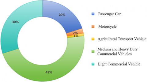
Figure 1. The share of oil consumption by different vehicle types
As shown in Figure 1, medium and heavy-duty commercial vehicles account for approximately 47% of total carbon emissions within the transportation sector, despite occupying only 13% of the vehicle market share [2]. This discrepancy highlights their substantial contribution to CO₂ emissions. Given the relative route stability and centralized deployment of these vehicles, the construction of localized hydrogen refueling stations becomes highly feasible. Thus, promoting fuel cell-powered heavy-duty trucks is considered an essential strategy for decarbonizing road freight [3].
The performance and lifespan of a fuel cell vehicle (FCV) are closely tied to the quality of system parameter matching. Importantly, this matching also governs heat distribution, energy utilization efficiency, and the thermal durability of core components. Achieving a well-balanced power system that satisfies both dynamic performance and thermodynamic efficiency is key. Currently, mainstream architectures involve various auxiliary energy source configurations such as Fuel Cell + Power Battery (FC+B), Fuel Cell + Supercapacitor (FC+C), and Fuel Cell + Battery + Supercapacitor (FC+B+C), chosen based on different application scenarios and thermal response behavior [4].
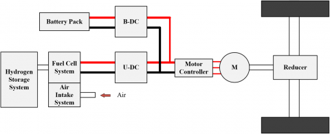
As illustrated in Figure 2, a common powertrain configuration employs two DC-DC converters—typically one for the fuel cell and one for the secondary battery—both interfacing with a common DC bus. This structure provides modular voltage control, enables optimized thermal management, and facilitates compatibility with mature high-voltage components, as seen in the Toyota Mirai [5-8].
Figure 2. Dual DC-DC based fuel cell vehicle drive system
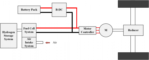
A second configuration, shown in Figure 3, omits the unidirectional DC-DC converter and directly connects the fuel cell to the DC bus. While this design reduces system complexity and conduction losses, it demands high consistency between the fuel cell's voltage range and the motor controller, thus imposing more stringent thermal balancing and voltage stability requirements. This configuration is adopted by the Hyundai ix35 FCV and Toyota FCHV-adv [9, 10].
Figure 3. Based on a bidirectional DC-DC fuel cell vehicle drive system
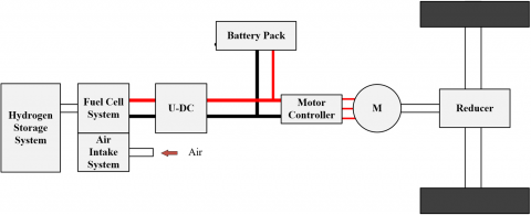
Figure 4. A fuel cell vehicle drive system based on a unidirectional DC-DC converter
The third structure, depicted in Figure 4, retains only a unidirectional DC-DC boost converter between the fuel cell and the DC bus, removing bidirectional components entirely. Used in the Honda FCX Clarity, this setup simplifies the system layout but requires precise control of thermal transients during load fluctuations [11].
Traditionally, the fuel cell and energy storage units are connected in parallel, with voltage matching achieved through appropriate DC/DC converter tuning. However, to meet the growing power and thermal demands of heavy-duty trucks, these systems often require high bus voltages. This increase leads to larger series battery packs and escalates the thermal load, complicating heat dissipation and increasing control complexity within the battery management system (BMS) [12, 13].
To overcome these challenges, multi-phase motor drive systems have gained attention for their ability to improve torque output, speed control range, and thermal distribution. These systems leverage multiphase inverters and motors, and their inherent redundancy also enhances system reliability under thermal stress [14]. For instance, the NIO ES8 has adopted a dual three-phase PMSM system, offering insights into scalable solutions for thermal and performance optimization [15].
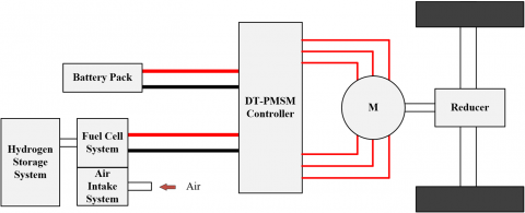
Figure 5. A fuel cell vehicle drive system based on a dual three-phase motor
As shown in Figure 5, this study investigates a high-power hydrogen fuel cell truck employing a dual three-phase permanent magnet synchronous motor (PMSM), each powered by an isolated inverter with independent energy sources. This topology allows direct regulation of power distribution and heat generation via coordinated inverter control. It also enables thermal decoupling between subsystems, significantly enhancing system resilience and energy management flexibility [16].
However, systematic design and parameter matching studies specific to this topology remain limited, especially for heavy-duty applications. Therefore, this paper focuses on a fuel cell heavy-duty truck equipped with a 100 kW hydrogen fuel cell stack and a dual three-phase PMSM system. The research encompasses the selection and thermal evaluation of core components, dynamic modeling of the power system, and comprehensive thermal analysis using AVL Cruise software. Simulated driving conditions—such as acceleration, hill climbing, and steady-state cruising—are used to evaluate the vehicle's thermal behavior, energy transfer efficiency, and system stability. Through this framework, the study provides practical insights into integrating thermodynamic considerations into fuel cell vehicle powertrain design, offering valuable references for future high-power green mobility systems [17].
The power system of a 100 kW high-power hydrogen fuel cell heavy truck is inherently complex. Consequently, the power matching design must be founded on a control strategy that prioritizes the protection of the high-power hydrogen fuel cell. Based on the overall vehicle performance indicators, the parameters of the primary power components—namely the hydrogen fuel cell, power battery, and motor—should be appropriately matched.
2.1 Driving system configuration analysis
The power system of fuel cell vehicles includes a main energy source battery and an auxiliary energy source battery, as well as an engine and a transmission.
2.2 Whole vehicle parameters and design objectives
This study examines heavy trucks that utilize high-power hydrogen fuel cells, tailored for the sector of heavy freight transportation known for significant loads, predetermined routes, and extended distances. The fundamental parameters of the high-power hydrogen fuel cell heavy truck, aligned with its market positioning and design specifications, are presented in Table 1.
Table 1. The basic parameters of the high-power hydrogen fuel cell heavy truck
|
Parameters |
Values |
|
Curb weight of the entire vehicle |
12000kg |
|
Gross vehicle weight |
42000kg |
|
$C_D * A$ |
0.65*9.45 |
|
Vehicle efficiency $\eta$ |
0.9 |
|
Minimum vehicle speed (climbing speed) |
10km/h |
|
Rolling resistance coefficient f |
0.012 |
|
Rolling radius |
0.512m |
|
Motor overload coefficient $\lambda$ |
2(4-5) |
|
Transmission ratio i |
0.92 |
|
Wheelbase |
4200mm |
|
Center of gravity height of the vehicle |
1205.9mm |
|
Maximum climbing gradient |
≥20% |
|
Maximum vehicle speed |
80km/h |
|
0-50km/h Acceleration time |
≤50s |
3.1 Control strategy for power system parameter matching
Compared to low-power hydrogen fuel cells, a 100 kW high-power hydrogen fuel cell can effectively meet the power demands of heavy-duty trucks under typical road conditions, thus serving as the primary power source. Due to the considerable payload, major fluctuations in load, and intricate road conditions linked to heavy-duty trucks, the entire vehicle's power needs frequently vary significantly. Consequently, the hydrogen fuel cell frequently experiences considerable power fluctuations, operates continuously under high load with low efficiency, and undergoes rapid load changes, resulting in suboptimal chemical conditions and reduced system efficiency. While the lifespan of hydrogen fuel cells is relatively long under steady-state conditions, it diminishes rapidly under high-frequency variable-load scenarios. Additionally, due to technological constraints, hydrogen fuel cells tend to be relatively expensive. Therefore, implementing a hydrogen fuel cell protection priority control strategy can lower the overall vehicle cost and enhance economic efficiency. In conclusion, when designing the power system for heavy-duty trucks, it is essential to adopt a control strategy that prioritizes the protection of the high-power hydrogen fuel cell, ensuring its operation within an efficient range from startup to shutdown. The overall operational procedure ought to focus on reducing the likelihood of unfavorable chemical conditions in order to enhance the effectiveness of the power system and prolong the lifespan of the hydrogen fuel cell [18].
3.2 Motor parameter matching
The design of a power system for heavy-duty trucks that employs high-power hydrogen fuel cells should begin by identifying the parameters related to the electric motor. This motor's power includes the requirements for maximum speed, the power needed for maintaining speed while climbing, and the energy essential for acceleration on flat terrain. The peak power value from these three situations indicates the rated power of the propulsion motor [19].
(1) The required power at the maximum speed of 80 km/h on a 0% gradient (considering only rolling resistance and air resistance).
$P_{v \max }=\frac{1}{\eta_t \eta_{\operatorname{mot}}}\left(\frac{m g f}{3600} v_{\max }+\frac{C_D A}{76140} v_{\max }^3\right)=120 \mathrm{~kW}$
$\eta_t$ -Transmission system efficiency is taken as 0.92, and motor efficiency is taken as 0.96.
(2) Maximum climbing power
Based on the performance metrics for heavy-duty trucks powered by fuel cells, these vehicles should be able to climb a gradient of 20% while ensuring a steady speed of 10 km/h when fully loaded. In the process of climbing, the influence of acceleration resistance can be ignored. The equation used to determine the power necessary for the motor is outlined below:
$P_{i \max }=\frac{1}{\eta_t \eta_{\operatorname{mot}}}\left(\frac{m g f}{3600} v_i \cos \alpha_{\max }+\frac{C_D A}{76140} v_i^3+\frac{m g v_i}{3600} \sin \alpha_{\max }\right)=145 \mathrm{~kW}$
$v_i$-The driving speed of the truck when fully loaded.
$\alpha_{\max }$-The degree of the maximum gradient at a specific driving speed.
(3) 0-50 km/h acceleration power
To determine the power needed for a heavy truck powered by a fuel cell to accelerate uniformly to a speed v on a level road within a time period t, the formula is:
$P_{a \max }=\frac{1}{\eta_t \eta_{\operatorname{mot}}}\left(\frac{m g f}{3600} v_a+\frac{C_D A}{76140} v_a{ }^3+\frac{\delta m v_a}{3600} \frac{d v}{d t}\right)=150 \mathrm{~kW}$
t-The minimum time required to accelerate from 0 to 50 km/h, with a stipulation of not less than 50 seconds, and here 25 seconds is chosen.
$\delta$-The conversion coefficient for the rotating mass of the heavy truck is taken as 1.02.
$v_a$-The final velocity of the vehicle during acceleration, 50 km/h.
To achieve the best performance of the complete vehicle, the drive motor's rated power in fuel cell heavy trucks needs to fulfill the demands for top speed, steep gradient capability, and acceleration duration. In particular, the rated power of the drive motor must comply with these specified criteria:
$P_e \geq\left\{P_{\mathrm{v} \max }, P_{i \max }, P_{a \max }\right\}$
Taking into account the efficiency and power needs of heavy trucks, this vehicle design has chosen a motor that delivers a rated power of 150 kW, can reach a peak power of 250 kW, and features an overload coefficient of 1.67, in combination with current motor models offered by suppliers in the market.
The connection between the highest driving speed of the complete vehicle and the peak rotational speed of the electric motor is:
$n_{\max }=\frac{v_{\max } l}{0.377 r}=3500$
The rated rotational speed of the electric motor is:
$n_e=\frac{n_{\max }}{\mu}=1800$
The coefficient for expanding the constant power range of the electric motor is crucial. A larger value results in a lower rated speed and a corresponding increase in torque, which enhances the vehicle's acceleration and climbing capabilities. It is crucial to recognize that the rise in torque requires a more substantial power converter. For this analysis, we have chosen a coefficient value in the typical range of 2 to 3, specifically selecting 2.
Using the initial two steps, it is possible to determine rated power and rotational speed of the motor. Additionally, utilizing the formula provided earlier allows for the calculation of the motor's rated torque.
$T_e=\frac{9550 * 150}{1800}=796 \mathrm{Nm} 800 \mathrm{Nm}$
The peak torque of the electric motor is:
$T_{\max }=\frac{9550 P_{\max }}{n_e}=1326 \mathrm{Nm} 1400 \mathrm{Nm}$
The main parameters of the electric motor are shown in the Table 2.
Table 2. The main parameters of the electric motor
|
Parameters |
Values |
|
Motor type |
Permanent Magnet Synchronous Motor |
|
Rated/Peak Power (kW) |
150/250 |
|
Rated/Peak Torque (Nm) |
800/1400 |
|
Rated/Peak Speed (rpm) |
1800/3500 |
3.3 Determination of transmission ratio
The power system of a high-power fuel cell heavy truck can determine the necessary power source capacity based on the motor power and transmission ratio. The transmission ratio is calculated according to dynamic design objectives, including maximum speed and maximum gradient.
(1) Determination of the minimum transmission ratio
The minimum transmission ratio is determined by the maximum motor speed and the maximum vehicle speed. The calculation formula is as follows:
$i_{\min }=\frac{0.377 n_{\max } r}{u_{\max }}$
(2) Determination of the maximum transmission ratio [20]
The highest transmission ratio can be determined using the driving resistance at the steepest gradient along with the motor's maximum output torque. The calculation for this is provided in the formula below:
$\begin{gathered}i_{\max} \geq F_{i \max} r / \eta_t T_{\max} \\ i_{\max } \leq 0.377 n_{\min} r / u_{\min}\end{gathered}$
The driving resistance at the maximum gradient is represented by $F_{\text {imax}}$; $n_{\text {min}}$ denotes the motor's minimum steady-state rotation speed; and $u_{\text {min}}$ signifies the heavyduty truck's minimum steady-state vehicle speed. The parameters for the transmission ratio chosen for this design are listed in Table 3.
Table 3. The transmission ratio parameters
|
Parameters |
Values |
|
Number of gears in transmission |
6 |
|
Main reduction ratio of transmission |
6.833 |
|
Drive axle ratio |
4.11 |
3.4 Parameter matching of the fuel cell
Currently, Proton Exchange Membrane Fuel Cells (PEMFC) are the most widely utilized fuel cells in the automotive sector. This prevalence is attributed to several advantages of PEMFCs, including rapid start-up, low operating temperatures, high power density, adjustable output power, and superior energy efficiency. This paper also adopts PEMFC as the primary energy source for fuel cell heavy trucks.
The power output of the hydrogen fuel cell system represents a vital factor. It needs to sufficiently fulfill the energy requirements of fuel cell vehicles under standard driving conditions. In the case of for fuel cell heavy trucks, the usual driving speed varies between 40 and 60 km/h. Therefore, the fuel cell system's output power must comply with the following equation:
$P_{f c}=\frac{1}{\eta_{D C} \eta_t}\left(\frac{m g f}{3600} u+\frac{C_D A}{76140} u^3\right)+P_{c h}$
Table 4. The fuel cell selection parameters
|
Parameters |
Values |
|
Fuel type |
Hydrogen |
|
Stack dimensions /mm |
1100×510×250 |
|
Cooling method |
Liquid cooling |
|
Operating environment temperature /℃ |
-30~45 |
|
Hydrogen source pressure /MPa |
35 |
|
Rated power /kW |
110 |
|
Peak power /kW |
150 |
|
Output voltage range /V |
260-500 |
|
Output current range /A |
0-500 |
In the formula: $\eta_{D C}$ is the DC/DC efficiency; $P_{c h}$ is the power consumption of other electrical units. Compared to the traditional parallel configuration, the accessories of the high-power hydrogen fuel cell system are relatively reduced, approximately $5 \mathrm{~kW} . u$ is the common driving speed of the fuel cell heavy truck, taking $u=60 \mathrm{~km} / \mathrm{h}$; therefore, its output power $P_{f c}$ is 110 kW . The fuel cell selection parameters for this design are shown in Table 4.
3.5 Power battery pack parameter matching
During the operation of the vehicle, the power battery supplies instantaneous power, facilitating "peak shaving and valley filling." This function allows the fuel cell system to operate smoothly and maintain a high-efficiency range, thereby minimizing fluctuations in output power. When the vehicle brakes, the power battery recovers braking energy. Under certain conditions, the hydrogen fuel cell heavy-duty truck must also operate in pure electric mode for a specified distance. To guarantee that the driving range of the heavy-duty truck powered by hydrogen fuel cells is adequate, it is essential for the power battery to exhibit a high energy density. Additionally, to meet instantaneous power demands, the power battery should also exhibit adequate power density and have a prolonged service life. Furthermore, it is crucial to emphasize environmental protection to prevent pollution.
Lithium batteries based on phosphoserine are commonly employed in new energy vehicles because of their excellent power and energy density, dependable and safe functionality, minimal self-discharge rates, extended lifespan, and lack of heavy metal contaminants. This paper investigates the application of phosphoserine lithium power batteries as an additional energy source for heavy-duty trucks utilizing hydrogen fuel cells.
To fulfill real-world usage needs, the heavy-duty truck powered by a hydrogen fuel cell must have the capability to cover a distance of no less than 100 km at a speed of 40 km/h while operating in pure electric mode, during which the output power of the power battery, Pb, is:
$P_b=\frac{u_c}{3600 \eta_t \eta_{b a t}}\left(m g f+\frac{C_D A u_c^2}{21.15}\right)$
In the formula, $\eta_{\text {bat}}$ is the discharge efficiency of the power battery, 0.95.
The energy Eb needed for the heavy-duty truck powered by hydrogen fuel cells to cover a distance of 100 kilometers while maintaining a constant speed of 40 kilometers per hour is:
$E_b=P_b \cdot t=\frac{P_b \cdot S}{u_c}$
In the formula, S represents the driving distance, S = 100 km.
The total electrical energy consumed has the following relationship with the capacity C of the power battery:
Table 5. The parameters of the power battery
|
Parameters |
Values |
|
Battery pack rated voltage /V |
576 |
|
Battery pack capacity /Ah |
228 |
|
Rated charge-discharge rate /C |
1 |
|
Peak charge-discharge rate /C |
2 |
|
Thermal management strategy |
Film heating for heating, Liquid cooling |
|
Charging method |
Single-gun fast charging |
$C=\frac{1000 E_b}{U_0}$
In the formula, $U_0$ is the nominal voltage of the power battery. The selected drive motor voltage is 560 V. Considering factors such as line loss and market supply, the nominal voltage of the power battery is taken as 576 V, and its capacity is determined to be 228 Ah. The final matched parameters of the power battery are shown in Table 5.
To thoroughly evaluate the rationality and effectiveness of the parameter matching within the heavy-duty truck power system, particularly under a control strategy that prioritizes the protection of high-power hydrogen fuel cells, we utilize AVL Cruise software. This software is closely aligned with engineering methodologies, enabling the creation of models for different elements of the high-power hydrogen fuel cell heavy-duty truck power system, in addition to the overall vehicle model. Following this, we proceed to analyze and enhance these models.
4.1 Modeling of the power system for high-power hydrogen fuel cell heavy-duty trucks
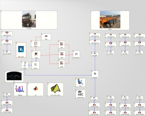
In alignment with the control strategy that emphasizes the safeguarding of high-power hydrogen fuel cells, the selection of these fuel cells and the accompanying design of the power system have been finalized, including the specification of component parameters. Consequently, a preliminary verification of the matching design results is necessary. A model for a cruise vehicle designed for high-power hydrogen fuel cell heavy-duty trucks has been developed based on the specifications of each component. These components consist of modules including the hydrogen fuel cell, power battery pack, motor, brakes, transmission, wheels, and vehicle controller. The simulation model of the power system for the high-power hydrogen fuel cell heavy-duty truck is illustrated in Figure 6.
Figure 6. Simulation model of high-power hydrogen fuel cell heavy-duty truck power system
4.2 Simulation result analysis
(1) C-WTVC working condition analysis
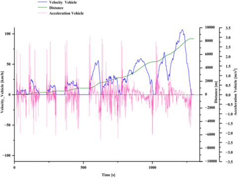
Considering the market positioning and performance requirements of high-power hydrogen fuel cell heavy-duty trucks, this study selects a typical Chinese heavy-duty vehicle test condition (C-WTVC) that aligns with the actual circumstances in China for analysis. The dynamic simulation results of the C-WTVC operating conditions for high-power hydrogen fuel cell heavy-duty trucks are presented in Figure 7.
Figure 7. Speed, acceleration, and distance variation curves
According to Figure 7, the cycle time is 1800 seconds, and the driving distance is 8.2 km. The maximum speed recorded is 85 km/h, while the average speed is 41.08 km/h. The maximum absolute value of acceleration is 3.0 m/s², with an average acceleration of 0.02 m/s². Throughout the entire process, the maximum speed meets the design performance requirement of ≥ 80 km/h. Additionally, both speed and acceleration exhibit good consistency with the trends observed in the road spectrum changes.
Figure 8. SOC variation curve of power battery
Figure 8 illustrates the variation curve of the State of Charge (SOC) for the auxiliary energy power battery pack of a high-power hydrogen fuel cell heavy-duty truck under the C-WTVC working condition. The SOC of the power battery pack fluctuates between 70% and 90%, starting from an initial value of 70%. This fluctuation aligns with the principle of shallow charging and discharging for the power battery pack, indicating that the operational point of the hydrogen fuel cell is situated within its high-efficiency working range.
As illustrated in Figure 8, hydrogen fuel cells, power cells, and motors predominantly operate within their rated range, with only brief instances of overload. The motor power demonstrates a strong correlation with the road spectrum trend, while the hydrogen fuel cell consistently operates within its efficient working area.
These results suggest that the parameter matching of the heavy-duty truck power system, under the protection priority control strategy for high-power hydrogen fuel cells, effectively meets the driving requirements of the C-WTVC cycle. This finding confirms that the parameter matching design for the high-power hydrogen fuel cell heavy-duty truck power system, under this control strategy, is both reasonable and effective.
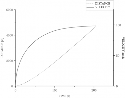
Figure 9. Maximum speed and driving distance curve
(2) Dynamic analysis
(a) The maximum speed of the hydrogen fuel cell heavy-duty truck, as illustrated in Figure 9, is 100 km/h, which meets the performance requirement of a minimum speed of 80 km/h.
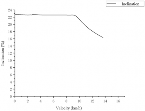
(b) The maximum climbing slope of the for fuel cell heavy trucks, as illustrated in Figure 10, is 22.74%. At a speed of 10 km/h, the climbing slope measures 21.22%, which satisfactorily meets the design objective of achieving a climbing slope of at least 20% at that speed.
Figure 10. Climbing performance
(3) Analysis of driving range
(a) Full charge driving range of power battery pack
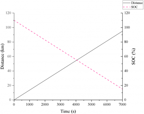
The assessment of the power battery pack's fully charged driving range occurs under a driving condition maintaining a constant speed of 60 km/h. The distance covered, as the state of charge (SOC) of the power battery pack shifts from an initial 90% down to 15%, indicates its fully charged driving range. Figure 11 presents the variation curve illustrating the relationship between the SOC values and the driving distance of the power battery pack under these operating conditions. As shown in Figure 9, the defined fully charged driving range for the power battery pack reaches 115 km, consistent with the design objective of ensuring a fully charged power battery achieves a minimum driving range of 50 km.
Figure 11. SOC and driving distance variation curve under constant speed condition of 60 km/h
(b) Continuous driving range under cyclic conditions
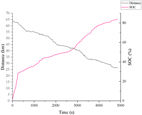
Under the C-WTVC cycle condition, the state of charge (SOC) of the power battery pack decreases from 90% to 15%. The variation curve of SOC and driving distance is illustrated in Figure 12. According to this figure, the driving distance during which the SOC declines from 90% to 15% under these operating conditions is 64 km. Given that the power source of heavy trucks consists of hydrogen fuel cells and power batteries, and considering that the design goal is to achieve a range of 50 km in pure-electric mode, this performance meets the established design requirements endurance.
Figure 12. C-WTVC cycle SOC and driving distance variation curve
The variation curves for the State of Charge (SOC) and driving range under the conditions of the C-WTVC cycle were developed for a heavy-duty truck power system powered by a high-performance hydrogen fuel cell, which utilizes a dual three-phase permanent magnet synchronous motor. This encompasses the selection of components, matching of parameters, and various calculations. In light of the operating conditions of the C-WTVC, the fuel cell was chosen after considering both the real-world operating conditions and the efficiency characteristics pertinent to heavy-duty trucks, to ensure that the motor performance specifications aligned with the component requirements. Using the outcomes of the design, a model representing the high-capacity hydrogen fuel cell heavy-duty truck was created in AVL Cruise, leading to several conclusions derived from simulation results.
(1) In this configuration, both the hydrogen fuel cell and the power cell operate within the high-efficiency range, exhibiting minimal instances of overcharging and over-discharging;
(2) The motor overload time is relatively short;
(3) The power system configuration of the heavy-duty truck with a fuel cell can fulfill the performance demands required for such vehicles.
The findings of this study illustrate that the process of designing a power system for series hydrogen fuel cell heavy-duty trucks, which employ dual three-phase permanent magnet synchronous motors, is both practical and efficient. As a result, this paper provides an important resource for future investigations into high-power applications of hydrogen fuel cell heavy-duty trucks.
This work was supported by the Inner Mongolia Scientific and Technological Projects (Grant No.: 2023YFHH0110).
[1] Zhao, X., Wang, J., Fu, X., Zheng, W., Li, X., Gao, C. (2022). Spatial-temporal characteristics and regional differences of the freight transport industry’s carbon emission efficiency in China. Environmental Science and Pollution Research, 29(50): 75851-75869. https://doi.org/10.1007/s11356-022-21101-4
[2] Longo, K., Wang, X., Zhao, H. (2024). Impact of diesel-hythane dual-fuel combustion on engine performance and emissions in a heavy-duty engine at low-load condition. International Journal of Engine Research, 25(2): 276-292. https://doi.org/10.1177/14680874231170651
[3] Charnah, R.M. (2000). Fuel cell drives for road vehicles. Journal of Power Sources, 86(1-2): 130-133. https://doi.org/10.1016/S0378-7753(99)00483-8
[4] Jiang, H., Xu, L., Li, J., Hu, Z., Ouyang, M. (2019). Energy management and component sizing for a fuel cell/battery/supercapacitor hybrid powertrain based on two-dimensional optimization algorithms. Energy, 177: 386-396. https://doi.org/10.1016/j.energy.2019.04.110
[5] Rahman, A.U., Ahmad, I., Malik, A.S. (2020). Variable structure-based control of fuel cell-supercapacitor-battery based hybrid electric vehicle. Journal of Energy Storage, 29: 101365. https://doi.org/10.1016/j.est.2020.101365
[6] Sun, H., Fu, Z., Tao, F., Zhu, L., Si, P. (2020). Data-driven reinforcement-learning-based hierarchical energy management strategy for fuel cell/battery/ultracapacitor hybrid electric vehicles. Journal of Power Sources, 455: 227964. https://doi.org/10.1016/j.jpowsour.2020.227964
[7] Toyota, Honda get ready to launch their FCVs. Fuel Cells Bulletin, 2014(11): 1. https://doi.org/10.1016/S1464-2859(14)70297-4
[8] Aso, S., Kizaki, M., Mizuno, H. (2009). Development progress of the Toyota fuel cell hybrid vehicle. SAE International Journal of Engines, 1(1): 296-303. https://doi.org/10.4271/2008-01-0420
[9] Bono, T., Kizaki, M., Mizuno, H., Nonobe, Y., Takahashi, T., Matsumoto, T., Kobayashi, N. (2009). Development of new TOYOTA FCHV-adv fuel cell system. SAE International Journal of Engines, 2(1): 948-954. https://doi.org/10.4271/2009-01-1003
[10] Toyota opens up its patents to boost FCEV industry collaboration. Fuel Cells Bulletin, 2015(1): 9-10. https://doi.org/10.1016/S1464-2859(15)70021-0
[11] Alcázar-García, D., Martínez, J.L.R. (2022). Model-based design validation and optimization of drive systems in electric, hybrid, plug-in hybrid and fuel cell vehicles. Energy, 254: 123719. https://doi.org/10.1016/j.energy.2022.123719
[12] Chen, X., Zhong, J., Wei, J. (2022). Research on modeling and simulation of fuel cell bus power system based on forward-backward energy flow balance method. Science Progress, 105(1): 00368504211064476. https://doi.org/10.1177/00368504211064476
[13] Li, Z., Onar, O., Khaligh, A., Schaltz, E. (2009). Design and control of a multiple input DC/DC converter for battery/ultra-capacitor based electric vehicle power system. In 2009 Twenty-Fourth Annual IEEE Applied Power Electronics Conference and Exposition, Washington, DC, USA, pp. 591-596. https://doi.org/10.1109/APEC.2009.4802718
[14] Boumegouas, M.K.B., Kouzi, K. (2022). A new synergetic scheme control of electric vehicle propelled by six-phase permanent magnet synchronous motor. Advances in Electrical and Electronic Engineering, 20(1): 1. https://doi.org/10.15598/aeee.v20i1.4221
[15] Zou, J., Liu, C., Xu, Y., Yu, G. (2023). A high-precision model for dual three-phase PMSM considering the effect of harmonics, magnetic saturation, and electromagnetic coupling. IEEE Transactions on Transportation Electrification, 10(2): 2456-2468. https://doi.org/10.1109/tte.2023.3299965
[16] Hu, S., Liang, Z., Zhang, W., He, X. (2017). Research on the integration of hybrid energy storage system and dual three-phase PMSM drive in EV. IEEE Transactions on Industrial Electronics, 65(8): 6602-6611. https://doi.org/10.1109/tie.2017.2752141
[17] Leonard, A. T., Salek, F., Azizi, A., Resalati, S. (2022). Electrification of a class 8 heavy-duty truck considering battery pack sizing and cargo capacity. Applied Sciences, 12(19): 9683. https://doi.org/10.3390/app12199683
[18] Liang, Z., Liu, K., Huang, J.J., Zhou, E. et al. (2022). Powertrain design and energy management strategy optimization for a fuel cell electric intercity coach in an extremely cold mountain area. Sustainability, 14(18): 11253. https://doi.org/10.3390/su141811253
[19] Sarigiannidis, A.G., Beniakar, M.E., Kladas, A.G. (2016). Fast adaptive evolutionary PM traction motor optimization based on electric vehicle drive cycle. IEEE Transactions on Vehicular Technology, 66(7): 5762-5774. https://doi.org/10.1109/tvt.2016.2631161
[20] Gong, N., Yi, F., Wang, J., Yuan, Z., Li, Z., Chen, Y. (2024). Matching and optimization of a pure electric vehicle transmission system equipped with a continuously variable transmission gearbox. In Fourth International Conference on Mechanical, Electronics, and Electrical and Automation Control (METMS 2024), Xi'an, China, pp. 2245-2252. https://doi.org/10.1117/12.3030281