Madhu Kalyan Reddy Pulagam![]() | Sachindra Kumar Rout*
| Sachindra Kumar Rout*![]() | Kamal Kanta Muduli
| Kamal Kanta Muduli![]() | Shoeb Ahmed Syed
| Shoeb Ahmed Syed![]() | Debabrata Barik
| Debabrata Barik![]() | Ahmed Kadhim Hussein
| Ahmed Kadhim Hussein![]()
© 2024 The authors. This article is published by IIETA and is licensed under the CC BY 4.0 license (http://creativecommons.org/licenses/by/4.0/).
OPEN ACCESS
This article presents an in-depth analysis of internally finned tube heat exchangers, which are used in a broad variety of condensers and evaporators for air conditioners, as well as radiators for vehicles and solar air heaters, amongst other places. The growing need for cooling systems that are more efficient and heat exchangers that take up less space has inspired many studies in this area of expertise. This research uses both experimental and computational analysis to compare and contrast the efficacy of various heat transfer enhancement processes in internally finned tube heat exchangers concerning the impacts they each have and the operating parameters they each need. This study aims to investigate how altering the fins' design affects heat transfer and pressure drop under varying operational situations. This paper examines the ranges in which these correlations have been verified, as several correlations have been created to assist in estimating heat transfer and pressure drop characteristics on internally finned tube heat exchangers. This study extensively delves into various analytical approaches such as Log Mean Temperature Difference (LMTD), Computational Fluid Dynamics (CFD), Finite Element Analysis (FEA), and other methodologies specifically tailored to address the unique goals of the particular problem. To derive a conclusion with practical significance, we categorize these relationships into multiple groups and conduct a comparative analysis.
internally finned tube, heat transfer coefficient, friction factor, Nusselt number
Fin and tube heat exchangers (FTHE) refers to a kind of heat exchanger that is widely used in a wide variety of sectors, including the creation of hydrogen, the cooling of electronic components, the pharmaceutical and chemical engineering industries, electrically heated cylinders, nuclear power plants, and compact heat exchangers [1]. However, the future trend of heat exchanger devices will encounter problems in terms of reducing size and weight, improving the efficiency of heat transmission, and lowering costs [2]. Over the course of the last several decades, researchers have made great progress toward the goal of improving the effectiveness of these heat exchangers. They used experimental, analytical, and computational methods in order to assess the efficacy of FTHE and establish connections between the various parts of the design. While there is an abundance of review articles [3, 4] focusing on external finned tube heat exchangers, there is a noticeable lack of available surveys specifically addressing internal finned tubes. This particular area warrants special attention due to the wide range of applications where internal finned tubes are utilized [5]. Examples include petrochemicals, solar air heaters, metallurgy, gas turbine regenerators, waste heat recovery, compressor intercoolers, and natural gas heat transfer. The purpose of this research is to give a comprehensive analysis of recent advancements in the design of internal finned-tube heat exchangers as well as the mechanisms that are now in use. It investigates various fin designs and placements that may be used depending on the flow conditions. Figure 1 presents a schematic of an internally finned tube Heat Exchanger.
Microchannels, inserts in heat exchanger tubes, finned-tube performance under different flow conditions, plate-tube louvered finned heat exchangers with delta winglet vortex generators, spiral fin and tube heat exchangers, and the use of extended surfaces are some of the various methods that have been discussed for improving heat transfer. Other methods include the use of extended surfaces. Significant gains in heat transmission may be attributed to a variety of factors, including expanding the surface area available for heat transfer, decreasing the hydraulic diameter, and inserting a closed inner tube. Because of this configuration, the angle that exists between the temperature gradient and the velocity is reduced, which in turn results in an increase in the rate of heat transfer. It is important to point out that none of the previously published review studies have concentrated particularly on internal finned tube heat exchangers. Air is often utilized as a heat transfer fluid despite the fact that it has a low thermal conductivity; nonetheless, the air's forced convection coefficient inside the tube is rather low. As a solution to this problem, internal fins are inserted to improve convective heat transmission, which has shown to be an efficient and simple solution. In heat exchangers, a wide variety of fin forms, including plain fins, wavy or corrugated fins, louvered fins, offset strip fins, and perforated fins, have been used. Plain fins are the most common kind of fin. Because of its potential to increase the efficiency of heat transmission, plain fins are the kind of fin that is most typically used. The undulating surface of wavy or corrugated fins improves the flow path length and encourages better airflow mixing, which both contribute to improvements in heat transfer. Wavy or corrugated fins are sometimes referred to as wave fins. On the other hand, since there were obstacles, these results do not apply to the movement inside the building. As a direct consequence of this, the analysis becomes more involved and focused on the problems. Table 1 presents different fin shape used by researchers.
Table 1. Summary of fin shapes in existing research
|
Author |
Fin Shape |
Flow Regime and Findings |
|
Fabbri [6] |
Laminar flow. The optimization of an internally finned polynomial lateral profile is achieved through the utilization of a genetic algorithm. |
|
|
Al-Sarkhi and Abu-Nada [7] |
Laminar flow. An elevation in fin height leads to an augmentation in the Nusselt number. Meanwhile, the parameter fRe exhibits a decline as the number of fins N increases. |
|
|
Lin et al. [8] |
Laminar flow. In the case of a tube with low thermal conductivity, the temperature profiles differ between the inside wall and outside wall, even when the tube wall is thin. |
|
|
Huq et al. [9] |
Turbulent flow. Achieved 52% heat transfer enhancement using fined surfaces for same pumping power. |
|
|
Sakalis and Hatzikonstantinou [10] |
Laminar flow. The critical fin height corresponds to a product of the friction factor and Reynolds number equal to 0.85, and for the mean Nusselt number in thermally developed flow, it is 0.73. |
|
|
Yu et al. [11] |
Laminar to turbulent flow. The 20-waves tube exhibits an enhancement percentage ranging from 1082% to 107% when compared to a smooth tube, under conditions of identical mass flow rate and pumping power. |
|
|
Papadopoulos and Hatzikonstantinou [12] |
Laminar flow. The Nusselt (Nu) value had an enhancement of approximately 70% for medium fin heights and 110% for large fins. |
|
|
Palanichamy and Nagaraj [13] |
The fin configuration featuring a half-included angle ($\alpha$ = 14°) was reported as the optimal profile for enhancing heat transfer in internal fins. |
|
|
Tien et al. [14] |
Laminar flow. A maximum Nusselt number is observed when the nondimensional fin length is 0.8 and the fin number is below 14. |
|
|
Zdaniuk [15] et al. |
Laminar flow. Tube 8 attained the highest j-factor, while tube 1 exhibited the lowest f-factor. |
|
|
Tijing [16] |
Laminar to turbulent flow. The heat transfer rate demonstrated an increase ranging from 12% to 51% compared to the value of a plain tube, depending on the internal fin configurations employed. |
|
|
Zhang [17] |
Laminar flow. The complete melting, when utilizing internal–external fins with a fin length of 42 mm, was reduced to 43.3% compared to that of TTHX without fins. |
|
|
Mat [18] |
Laminar flow. Incorporating internal fins proves to be an effective method for augmenting heat transfer in thermal energy storage systems, particularly when employing a transfer fluid with low thermal conductivity. |
Figure 1. Schematic of internally finned tube heat exchanger
This review article focuses on the performance of internally finned heat exchangers in various applications, specifically with regard to the transfer of heat and the decrease of pressure. It takes into account the optimum parameters for the functioning of the heat exchanger as well as the correlations that have been developed for various circumstances. In general, this study presents a detailed assessment of the fundamental characteristics of several kinds of internally finned heat exchangers as well as creative design concepts, taking into consideration a variety of geometric parameters of fins and flow conditions.
The presence of fins inside tubes during fluid flow, especially in laminar flow, plays a crucial role in enhancing heat transfer. Researchers employ a variety of fin profiles to investigate the improvement of heat transfer and the resulting pressure drop. Fabbari [6] conducted mathematical study and optimization to figure out how to improve heat transfer in laminar flow by making use of finned tubes on the inside. In order to investigate the differences in speed and temperature throughout the tube's cross-section, they made use of a model that included finite elements. To determine the ideal form of the fins, an evolutionary method was used, and a polynomial representation of the lateral profile of the fins was supplied. Tests and computer simulations were used by Edwards and Jensen [19] to gather a large amount of information on the convective heat transfer that occurs in internally finned tubes. They came up with a way to forecast pressure drop and heat transfer rates in turbulent flow by employing a characteristic length for the flow as the input variable. The performance of finned tubes may be simply and precisely evaluated thanks to this correlation; which heat exchanger designers can employ. Table 2 displays a compilation of correlations developed by researchers for a comprehensive investigation of internal finned tubes.
For the purpose of calculating the outcomes of forced convection heat transfer, Al-Sarkhi et al. [7] carried out a numerical study on vertically oriented internally finned tubes. They did this by using fins that were positioned in a direction that was perpendicular to the axis of the tube. The number of fins ranged from five to eighty, and their height went from one tenth of an inch to nine tenths of an inch (dimensionless units). The flow regime and Reynolds number (Re) were greatly impacted by the hydrodynamic diameter as well as the pressure gradient. The Nusselt number, denoted by Nu, achieved its highest possible value at a certain number of fins and then began to decline as more fins were added.
Table 2. Summary of correlations used in existing research
|
Authors |
Nu |
Re Range |
Re Correlation |
Important Correlation |
Remarks |
|
Lin et al. [8] |
${{h}_{1\left( z \right)}}=~\frac{{{q}_{1wi}}}{{{T}_{wi\left( z \right)}}-~{{T}_{1a\left( z \right)}}}$ $N{{u}_{1\left( z \right)}}=~\frac{{{h}_{1\left( z \right)}}{{D}_{h}}}{\lambda }$ |
299–1,475 |
$Re=\frac{\rho {{u}_{m}}{{D}_{h}}}{\mu }$ |
${{\eta }_{f}}=\sqrt{2h/\lambda \delta }\cdot {{l}_{f}}/2N$ |
Experimental and numerical study. The fluid temperature profile is not linear but convex along the flow. Finite volume technique was used |
|
Al-Sarkhi and Abu-Nada [7] |
$Nu={{h}_{T}}\left( 2R \right)/K$ |
Re < 2000 |
$Re=\frac{{{\rho }_{w}}\bar{w}{{D}_{h}}}{\mu }$ |
$f=\frac{Dn\left( \frac{-\text{d}p}{dz}-{{\rho }_{w}}g \right)}{\frac{1}{2}{{\rho }_{w}}{{{\bar{w}}}_{2}}}$ |
Numerical study. Nusselt number increases with increasing fin height. Finite volume technique was used |
|
Yu and Tao [11] |
$N{{u}_{x}}=\frac{{{h}_{x}}{{D}_{h}}}{\lambda }$ |
880 –14700 |
$Re=\frac{{{u}_{m}}{{D}_{h}}}{\vartheta }$ |
${{f}_{x}}=\frac{-\frac{\text{d}P}{\text{d}x}{{D}_{h}}}{\frac{1}{2}\rho U_{m}^{2}}$ |
Experimental Study |
|
Palanichamy and Nagaraj [13] |
$Nu=\frac{2{{r}_{0}}h}{{{k}_{cm}}}$ |
1,500 |
|
The effectiveness is calculated by evaluating the ratio of heat transfer coefficient of the finned tube to that of the unfinned tube |
Numerical Study. The engine oil is found to be the effective coolant. enhancement. Finite difference numerical study |
|
Tien et al. [14] |
$Nu=\frac{2{{r}_{0}}*\overline{{{q}_{w}}}}{{{k}_{f}}\left( {{T}_{w}}-{{T}_{b}} \right)}$ |
Re < 2000 |
$\text{Re}=\frac{2\dot{m}}{\pi r_{0}^{*}\mu }$ |
$f=\frac{{{\pi }^{2}}\rho {{r}_{0}}^{*5}}{{{{\dot{m}}}^{2}}}\left( -\frac{\text{d}{{\rho }^{*}}}{\text{d}{{z}^{*}}} \right)$ |
Numerical Study. Heat transfer increase with increase of fin number but the pressure drop turns out to be large. Finite-difference scheme was used |
|
Rout et al. [20] |
$N{{u}_{avg}}=\frac{{{h}_{avg}}{{D}_{h}}}{{{k}_{air}}}$ |
1200 |
$Re=\frac{{{V}_{in}}{{D}_{h}}}{\vartheta }$ |
|
Numerical Study. The heat transfer is maximum for triangular-shaped fin as compared to rectangular and T-shaped fin. Finite volume technique was used |
Lin et al. [8] studied the influence of sinusoidal wavy fins on tube heat transfer at Reynolds numbers ranging from 299 to 1,475. The researchers used both computational and experimental methodologies to carry out their research. Tubes made of copper and stainless steel were studied while the identical boundary condition of an external heat flux was in place. They found that after three to five cycles, the axial profiles of the local Nusselt number returned to their original state. Within a range of 27%, the Nusselt values for highly conductive materials like copper varied by as much as 30 percent from one another. The largest difference in Nusselt number, on the other hand, was just 11% for a material with low heat conductivity (stainless steel).
Huq et al. [9] conducted a battery of experiments to determine how efficiently internally finned tubes transfer heat in a turbulent flow setting. When comparing the tube's initial development stage to its finalized state, they found that the finned tube's heat transmission was between 97% and 112% more efficient than that of a smooth tube. Sakalis and Hatzikonstantinou [10] performed a computer investigation to learn more about the connection between the fin height-to-tube radius ratio and the friction coefficients in a square duct. When the fin height was at its greatest, they found that the friction numbers had critical values of roughly 0.85, while the Nusselt numbers had critical values of approximately 0.73. In addition to this, they discovered that the length of the thermal entry rose up to a certain point, after which it began to decline even though the fin height remained the same.
Experimental examinations on tubes equipped with internal wave-like longitudinal fins were carried out by Yu et al. [21], who found that the heat transport was significantly improved as a result. They noticed gains in heat transfer of 1,082% and 107% when comparing a smooth tube to one with 20 waves.
In his research on laminar flow conditions in a curved square duct with longitudinal fins, Papadopoulos and Hatzikonstantinou [12, 22] found that the average height of the fins increased by 70%, while the rise in Nusselt number (Nu) for bigger fins was 110%. Using a finite difference numerical code, Palanichamy and Nagaraj [13] researched laminar heat transfer in circular tube flow with internal longitudinal fins. This flow configuration included heat transmission in a laminar state. The researchers discovered that the fins had only a little impact on the entrance length, which was found to be predominantly determined by the Dean number (De). However, the installation of fins resulted in a substantial increase in the rate of heat transmission. Tien et al. [14] performed a computer study of fully developed laminar flow and heat transport in internally finned tubes under a constant wall temperature boundary condition. They varied the fin thickness, length, number, and thermal conductivity ratio to get the friction factor and the Nusselt number as output variables. This allowed them to get knowledge about the fins' efficiency. The results showed that a considerable increase in heat transfer occurred when the number of fins was increased.
Zdaniuk et al. [15] conducted an experiment in which he assessed the friction factor and the heat transfer coefficient for a set of eight helically-finned tubes. He recommended Tube 8 for use in heat exchange applications owing to its high j-factors and mild f-factors over the whole Reynolds number range. The researchers Rout et al. [20, 23] carried out a numerical investigation in which they compared various fin numbers, heights, and shapes and came to the conclusion that the design of the triangular fin was the most effective. El-Sebaey et al. [24] numerically explored the thermos hydraulic performance of an internally longitudinal finned tube. Liu et al. [25] investigated numerically and experimentally on a cylindrical tube with internally spiral fins arranged in multiple waves. Their findings indicated that the friction factor (f) and heat transfer coefficient (h) for the finned pipe ranged from 5.39 to 5.84 and 7.94 to 8.67, respectively, in comparison to the plain tube.
Tijing et al. [16] conducted a series of experiments to investigate the impact that star-shaped internal fins have on the efficiency of a water-based counterflow heat exchanger in terms of both the increase of heat transfer and the performance of pressure drop. They discovered that there was a decrease in pressure drop by 283-399% and an increase in heat transfer by 12-51% when compared to a tube with a smooth surface. The Fluent 15 simulation tool was used by Acharya and Dash [26] to examine the effects of natural convection on a 3D internally finned horizontal cylinder. This was done in order to better understand how natural convection works. They calculated the conservation equations for mass, momentum, and energy, considering parameters such as the fin height, the fin spacing, and the cylinder length, to understand the behavior of the thermofluid. This allowed them to comprehend the behavior of the thermofluid. In addition to this, they devised a general correlation for the Nusselt number (Nu) that had an accuracy of around 6% and demonstrated the connection between a range of factors and the heat transfer characteristics.
The findings of these tests and studies, taken as a whole, give highly useful information regarding the enhancement, performance, and optimization of heat transfer in internally finned tubes that were exposed to laminar and turbulent flow conditions.
Because of their capacity to store or release huge quantities of energy during melting or solidification, phase change materials (PCMs) are extensively used in thermal storage systems. A portion of the space around the heat transfer fluid in a shell-and-tube heat exchanger is filled with a phase change material (PCM), which helps to guarantee that the fluid remains encased inside the tube. This helps to prevent the fluid from escaping via any holes that may be present in the tube. Studies done in the past have shown that increasing the number of fins on the PCM side of the system leads to an increase in the amount of heat transported when utilizing a fluid with a high thermal conductivity as the transfer medium. This was shown to be the case in the case of highly thermally conductive fluids. This was discovered when using the liquid as the medium for the transfer process. When air is employed as the heat transfer fluid, the convective heat transfer coefficient within the tube is significantly reduced. This is due to the fact that air has a poor thermal conductivity, which results in a reduced heat transfer coefficient. It is not the powertrain control module that is to blame for the majority of the heat transfer resistance in the system; rather, the culprit is the transfer fluid. For this reason, adding fins to the PCM side of a latent heat thermal energy storage system does not effectively enhance the system's capacity to transmit heat. Instead, it is essential to work on accelerating the heat transfer rate that occurs due to induced convection within the tube.
Zhang and Faghri [17] used a finite difference approach in their research to evaluate how adding interior fins to rectangular tubes may potentially improve heat transfer in latent heat thermal energy storage systems. Their research was centered on finding ways to increase the heat transfer rate in latent heat thermal energy storage devices that used rectangular tubes. When the fin thickness, height, and number were increased, they found a significant rise in the percentage of melting volume. A comparison was made between plain tubes and tubes that included internal fins, keeping the tube diameter and the volume of the transfer fluid constant throughout the experiment. This led to the discovery. According to the study's results, internally finned tubes are particularly helpful for boosting melting heat transfer in applications with low Reynolds numbers and transfer fluids that have poor thermal conductivity. This is because these conditions are present while molten metal is being transferred. The effects of the interior fins on the intensification of the melting process were more noticeable when the PCM was having a subcooling effect.
Figure 2. Triplex-tube heat exchanger with fins attached internally [18]
A quantitative examination of the melting process of a phase-change material known as RT 82 was carried out by Mat et al. [18] in a triplex-tube heat exchanger (TTHX) that included internal fins. During the course of the study, careful consideration was given to fins located on both the inside and outside of the object as shown in Figure 2. The length of each of these fins was measured to be exactly 42 millimeters. Compared to a design that did not have fins, the TTHX design did result in a reduction of 43.3% in the amount of time necessary for the full melting of the material. This was the case when comparing the TTHX design to another design.
The melting behavior of a PCM was analyzed by Shatikian et al. [27] using Fluent Six numerical simulations. The PCM was put underneath a heat sink that had vertical internal plate fins. The primary objective of this research was to analyze the transient phase transition process and its connection to a variety of various parameters, one of which was the size of the fins. The simulations indicated that the behavior of the phase change was reliant not only on the magnitude of the fins but also on a number of other critical parameters. This was the case even though the size of the fins was a major factor.
Lamberg and Sirén [28] investigated the solidification process in a discrete two-dimensional PCM storage device with metal internal fins that are straight. They used an analytical model predicated on a quasi-linear, transient, thin-fin equation with constant end-wall temperatures to study and analyze the solidification process when these internal fins were present. This research and analysis aimed to determine how the process worked when these internal fins were present.
An examination of inward solidification in a finned vertical tube latent heat storage unit was carried out by Velraj et al. [29]. This inquiry consisted of both an experimental and a numerical component. They researched how fins influenced the solidification process and found that the number of fins in the tube significantly reduced the length of time required for the process by a factor of around 1/n, where n represents the total number of fins in the tube. This discovery was founded on the realization that the quantity of fins included inside the tube resulted in an appreciable reduction in the total amount of time necessary for the procedure. The researchers also studied several other ways, such as fins, Lessing rings, and air bubbles, to boost the overall efficiency of a solar thermal storage system and expand the device's capability to transmit heat.
Heat pipes are well-known for their capacity to transmit heat effectively by using a mixture of evaporation and condensation as the two primary processes involved. This one-of-a-kind characteristic provides several benefits, some of the most notable of which are an impressively uniform temperature distribution down the axis of the heat pipe, a high equivalent axial thermal conductivity, and remarkable dependability. Because of these qualities, heat pipes are a very useful component in applications that call for the effective management of thermal energy and the efficient transfer of heat.
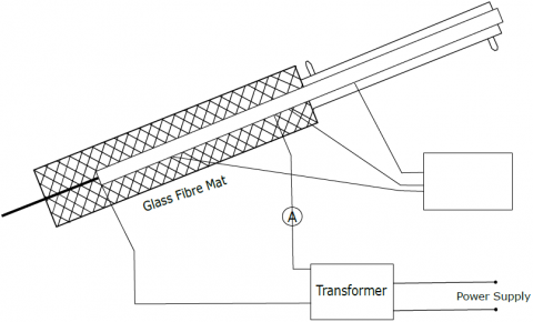
An experimental investigation of the thermal performance of an internally finned tube was carried out in research authored by Liao et al. [30]. The authors used the small inclined angle (2 to 13o) of internally finned tubes to study the heat transfer performance. It was discovered that an internally finned tube greatly increased heat transfer compared to a smooth tube under comparable operating circumstances, with a 50-100% enhancement in heat transfer coefficient for evaporation and a 100-200% improvement in condensation. Regardless of whether the tube was smooth or finned inside, this was the case. The experimental setup used by the authors are presented in Figure 3. Similarly, Naresh and Balaji [31] evaluated the performance of a two-phase closed internally finned thermosyphon using both experimental and computational studies. The condenser of the thermosyphon was rectangular and included internal fins as shown in Figure 4.
Figure 3. Experimental schematic diagram proposed by Liao et al. [30]
There was more than one function that the interior fins in the condenser were responsible for. To begin, they devised a way to stop a layer of condensation from forming on the film, making it possible for liquid to go from the condenser to the evaporator continuously. Second, the fins increased the total surface area, which allowed for a more efficient transfer of heat from the vapor to the fins. Additionally, the fins encouraged greater condensation, ensuring the system was supplied with a consistent amount of liquid. The filling ratio necessary to attain maximum performance was decreased due to these combined impacts.
Figure 4. Photographic view of condenser with fins attached internally [31]
According to the study results, increasing the number of fins on the condenser directly caused the condensation layer to break down immediately. Because of this, the liquid flow between the condenser and the evaporator was more consistent and proceeded faster, which ultimately led to a more rapid arrival at a steady-state condition. Additionally, installing fins led to an increase in condensation of 13%, which reduced the filling ratio required for optimum performance.
Because the exhaust gas from a gas-fired boiler includes a considerable amount of latent heat, it is possible to enhance energy efficiency by around 10% by recovering both the sensible and latent heat. In the 1970s, a condensing boiler was developed so that the latent heat in the flue gas from water vapor could be used. The use of a heat exchanger accomplished this. The finned tubes used on the inside of this specific boiler significantly improve the effectiveness of heat transfer and induce condensation. The end consequence is an increase in the amount of energy that is recovered. Wang et al. [32] have created a symmetric internally finned tube that utilizes theoretical and empirical methods to collect latent heat from the flue gas of gas-powered equipment. This tube is intended to be used to collect latent heat. The recommended finned tube has heat transfer coefficients that are anywhere from four to eight times higher than those of a smooth tube with the same diameter. They used various types of fins as presented in Figure 5.
The investigation of the effects of thermal stress on high-temperature heat exchangers was carried out by Zeng et al. [33], and they made use of the Ansys program in the course of their work. They utilized an equation that incorporated diffusion and added thermal boundary conditions to it in order to compute the temperature distribution throughout the heat exchanger. This equation allowed them to determine how the temperature varied across the heat exchanger. In addition, they explored the stress distribution by applying structural boundary conditions to stress equations established from thermo-elasticity mechanics. This allowed them to determine how the stress was distributed throughout the structure. In great detail, the researchers examined a wide range of lateral fin profiles, such as Z-shaped, S-shaped, and V-shaped versions (Figure 6), to assess how well these profiles performed their roles as heat transfer devices. Among these profiles, the Z-shaped fin was determined to have the best heat transfer efficiency and the most consistent performance. They also compared the average Von Mises stress of the fin in the middle section which is an indicator of the stress of plate-fin structure. According to the results of this research, using a lateral fin profile in the shape of a Z in high-temperature heat exchangers is likely to be a beneficial option for practical engineering applications. This conclusion was reached due to the study's investigation into the topic. It is a fantastic choice for these kinds of systems because to the exceptional heat transfer efficiency it has, in addition to the consistent and steady performance it provides.
Figure 5. Various shape fin structure used by author Wang et al. [32]
Figure 6. Temperature contours of Z, S and V shape fin used by Zeng et al. [33]
In recent years, the usage of internally finned tubes in parabolic trough collectors (PTCs) has attracted a significant amount of interest because it can transform solar irradiance into usable process heat efficiently. Because of this modification, gains have been made to the collector's exergetic and thermal efficiencies, as well as to the reduction of thermal losses and minimizing temperature changes inside the collection. These outcomes are all a direct result of the adjustment. Internally finned tubes increase the overall performance of PTCs by enhancing heat transfer, which allows PTCs to more effectively capture and utilise solar energy for a variety of applications. Internally finned tubes can be found in most modern PTCs.
An investigation of the effect that internally finned tubes have on PTC design was carried out by Munoz and Abánades [34] using computational fluid dynamics methods to look into the matter. Following the installation of internal fins, the plant's overall efficiency increased by 2%, as determined by the study. On the other hand, it was noted that parasitic losses owing to pressure losses in the tube also rose. This was ascribed to more fins and a steeper helix angle, contributing to the rise. These results point to a possible trade-off between increased plant efficiency and larger parasitic losses when employing internally finned tubes in PTC systems.
Bellos et al. [35, 36] did a numerical study using SolidWorks Flow Simulation to investigate the effect of rectangular fins on the absorber of a parabolic trough collector. They found that there is a significant influence. They want to figure out the geometry that would work best for these fins. According to the research findings, the optimum performance was achieved by using rectangular fins that were 10 millimeters long and had a thickness of 2 millimeters. An energetic strategy was used to test many different working fluids, including air, helium, and carbon dioxide as shown in Figure 7. Compared to the other fluids investigated, helium consistently demonstrated the best efficiency in terms of exergy. In addition, the research found that the best mass flow rates for maximizing performance are 0.03 kilograms per second for helium and 0.015 kilograms per second for other working fluids.
Figure 7. The temperature contour in the middle of the tube for air, helium and carbon dioxide [35]
Kasperski and Nemś [37] used mathematical modeling to investigate how numerous fins in a solar air heater transfer and store heat to reach their conclusions. According to the research findings, using half-pipe fins as opposed to smooth pipe absorbers may improve effectiveness by up to 14% while simultaneously resulting in a considerable reduction in the amount of airflow needed by a ratio of 7-10. Similarly, Ho and Chen [38] built a mathematical model to examine the performance of a double-pass sheet-and-tube solar water heater with internal fins. At the same time, it was being put through cyclic operation. This analysis showed that the inclusion of fins increased the system's dependability.
In conclusion, using internally finned tubes in parabolic trough collectors gives benefits in higher efficiency and decreased heat losses. On the other hand, a trade-off is possible, including higher parasitic losses. Mathematical modeling and numerical simulations give vital insights into heat transfer processes and system optimization. Optimal fin shapes, working fluids, and mass flow rates are all ways to optimize the performance of these systems further. Hosseini and Sheikholeslami [39] utilized internally corrugated structures fins in solar photovoltaic units to enhance efficiency, both in solar photovoltaics and heat exchange devices.
Foong et al. [40] used numerical simulations to evaluate the influence of constant heat flux boundary conditions on heat transfer and fluid flow characteristics in a square microchannel with four longitudinal internal fins. This study aimed to determine how constant heat flux boundary conditions affect heat transfer and fluid flow characteristics. This was done to determine the extent to which the boundary conditions impacted heat transfer and fluid flow features. They discovered that the height of the microchannels should be 0.67 times that of the fins to acquire the largest possible gain in heat transfer from the design.
Flow-boiling and single-phase heat transfer in internally finned and micro-finned helical tubes were compared and contrasted in a series of tests by Li et al. [41]. These experiments were carried out to explore the differences between the two types of heat transfer. They discovered that increasing the number of fins on helical tubes led to a significant improvement in heat transfer compared to tubes with no fins. The Reynolds number was increased from 1000 to 8500, and the researchers discovered this was accurate. However, an increase in flow resistance was necessary to attain this improvement.
Wang et al. [42] investigated the effect of turbulent flow on pressure drop and heat transfer in tubes, using various configurations of internally longitudinal fins as part of their investigation. The researchers discovered that interrupted wavy fin tubes gave the highest gain in heat transmission, but this came at the price of a substantially bigger pressure drop compared to other fin designs. The presence of a periodic wavy wall in a channel can induce the formation of eddies in turbulent flow.
Masliyah and Nandakumar [2] investigated the heat transfer process by employing internally finned tubes fitted with triangle fins. Their findings were published in the journal Heat Transfer. They analyzed laminar completely evolved flow using the approach of finite elements, and the results led them to conclude that an internally finned tube performed better than a smooth tube in terms of the Nusselt number. Because of the investigation's findings, they came to this realization as a result. In addition, they concluded that the optimal number of heat transfer fins was required to achieve the highest possible quantity of heat transmission.
Patankar and Prakash [43] researched to investigate the influence of buoyancy on both free and forced convection in vertical tubes with internal fins. They researched straight radial fin designs and trials in which they altered the number of fins as well as the height of the structure. They concluded that buoyancy had a substantial influence not only on the number of frictional losses, but also on the heat transfer rates, as a result of their research and the data they obtained.
In a nutshell, the primary emphasis of this research was on the effect that varied fin designs would have on the heat transfer and flow properties of the many different kinds of tubes that were looked at. They brought attention to the trade-off associated with finned tubes, which is greater flow resistance in exchange for better heat transfer, and they underlined how important it is to optimize fin shape to get the most out of the efficiency of heat transmission.
An extensive review on the thermal-hydraulic characteristics of internally finned heat exchangers have been carried out. Based on different application differentiate of fanned structures are used for which heat transfer and fluid flow behavior were reviewed. The experiments on air, water, oil and refrigerant as well as the numerical researches were analyzed. Based on the review, the following conclusions were obtained:
·Finned tubes generally exhibit higher friction factors compared to smooth tubes, typically ranging from 3.2 to 4.5 times higher. Nevertheless, it is important to note that the slope of the friction factor curve for finned tubes closely resembles that of smooth tubes.
·In the entrance region, the Nusselt number demonstrates a relatively high value. However, as the axial distance increases, the Nusselt number gradually decreases and tends to approach the fully developed value in an asymptotic manner.
·With an increase in the height of the fins, both the product of the friction factor (f) and Reynolds number (Re) and the mean Nusselt number (Nu) of the thermally developed flow also experience an increase. This trend persists until reaching critical values.
·The mean Nusselt number of the thermally developing flow demonstrates an increase as the height of the fins increases.
·The thermal entrance length initially increases as the fin height varies up to a certain point, but beyond that height, it decreases sharply.
·Heat transfer enhancement in square curved channels can be greatly improved. Medium fin heights can result in approximately 70% enhancement in heat transfer, while large fins can provide an enhancement of about 110%. However, small fins do not offer a significant increase in the Nusselt number compared to a duct without fins.
·When working with low thermal conductivity transfer fluids and operating at low Reynolds numbers, internal fins prove to be a more effective approach for enhancing melting heat transfer.
This work is supported by the Papua New Guinea University of Technology, Papua New Guinea.
|
B |
dimensionless heat source length |
|
CP |
specific heat, J. kg-1. K-1 |
|
g k |
gravitational acceleration, m.s-2 thermal conductivity, W.m-1. K-1 |
|
Nu |
local Nusselt number along the heat source |
|
Greek symbols |
|
|
a |
thermal diffusivity, m2. s-1 |
|
b |
thermal expansion coefficient, K-1 |
|
f |
solid volume fraction |
|
Ɵ |
dimensionless temperature |
|
µ |
dynamic viscosity, kg. m-1.s-1 |
|
Subscripts |
|
|
p |
nanoparticle |
|
f |
fluid (pure water) |
|
nf |
nanofluid |
[1] Webb, R.L., Scott, M.J. (1980). A parametric analysis of the performance of internally finned tubes for heat exchanger application. Journal of Heat Transfer, 102(1): 38-43. https://doi.org/10.1115/1.3244245
[2] Masliyah, J.H., Nandakumar, K. (1976). Heat transfer in internally finned tubes. Journal of Heat Transfer, 98(2): 257-261. https://doi.org/10.1115/1.3450528
[3] Zheng, X.Y., Qi, Z.G. (2018). A comprehensive review of offset strip fin and its applications. Applied Thermal Engineering, 139: 61-75. https://doi.org/10.1016/j.applthermaleng.2018.04.101
[4] Abdulateef, A.M., Mat, S., Abdulateef, J., Sopian, K., Al-Abidi, A. (2018). Geometric and design parameters of fins employed for enhancing thermal energy storage systems: A review. Renewable and Sustainable Energy Reviews, 82: 1620-1635. https://doi.org/10.1016/j.rser.2017.07.009
[5] Liu, L., Sun, T., Cao, Y., Yu, X.L., Zhang, L., Cao, Z.Y., Zhang, L., Xu, W.G., Bu, S. (2023). Experimental and numerical investigation on the flow and heat transfer characteristics of the tube with an integrated internal longitudinal fin. International Journal of Thermal Sciences, 183: 107857. https://doi.org/10.1016/j.ijthermalsci.2022.107857
[6] Fabbri, G. (1998). Heat transfer optimization in internally finned tubes under laminar flow conditions. International Journal of Heat and Mass Transfer, 41(10): 1243-1253. https://doi.org/10.1016/S0017-9310(97)00209-3
[7] Al-Sarkhi, A., Abu-Nada, E. (2005). Characteristics of forced convection heat transfer in vertical internally finned tube. International Communications in Heat and Mass Transfer, 32(3-4): 557-564. https://doi.org/10.1016/j.icheatmasstransfer.2004.03.015
[8] Lin, M., Tian, L., Wang, Q.W. (2011). Laminar heat transfer characteristics of internally finned tube with sinusoidal wavy fin. Heat and Mass Transfer, 47(6): 641-653. https://doi.org/10.1007/s00231-010-0757-5
[9] Huq, M., Huq, A.A.M., Rahman, M.M. (1998). Experimental measurements of heat transfer in an internally finned tube. International Communications in Heat and Mass Transfer, 25(5): 619-630. https://doi.org/10.1016/S0735-1933(98)00049-9
[10] Sakalis, V.D., Hatzikonstantinou, P.M. (2001). Laminar heat transfer in the entrance region of internally finned square ducts. Journal of Heat Transfer, 123(6): 1030-1034. https://doi.org/10.1115/1.1404118
[11] Yu, B., Tao, W.Q. (2004). Pressure drop and heat transfer characteristics of turbulent flow in annular tubes with internal wave-like longitudinal fins. Heat and Mass Transfer, 40(8): 643-651. https://doi.org/10.1007/s00231-003-0449-5
[12] Papadopoulos, P.K., Hatzikonstantinou, P.M. (2005). Thermally developing flow in curved square ducts with internal fins. Heat and Mass Transfer, 42(1): 30-38. https://doi.org/10.1007/s00231-004-0572-y
[13] Palanichamy, R., Nagaraj, P. (2010). Numerical simulation of laminar heat transfer in aluminium circular tube with internal longitudinal fins. International Journal of Modelling and Simulation, 30(2): 204-210. https://doi.org/10.1080/02286203.2010.11442574
[14] Tien, W.K., Yeh, R.H., Hsiao, J.C. (2012). Numerical analysis of laminar flow and heat transfer in internally finned tubes. Heat Transfer Engineering, 33(11): 957-971. https://doi.org/10.1080/01457632.2012.654729
[15] Zdaniuk, G.J., Chamra, L.M., Mago, P.J. (2008) Experimental determination of heat transfer and friction in helically-finned tubes. Experimental Thermal and Fluid Science, 32(3): 761-775. https://doi.org/10.1016/j.expthermflusci.2007.09.006
[16] Tijing, L.D., Pak, B.C., Baek, B. J., Lee, D.H., (2006). A study on heat transfer enhancement using straight and twisted internal fin inserts. International Communications in Heat and Mass Transfer, 33(6): 719-726. https://doi.org/10.1016/j.icheatmasstransfer.2006.02.006
[17] Zhang, Y.W., Faghri, A. (1996). Heat transfer enhancement in latent heat thermal energy storage system by using the internally finned tube. International Journal of Heat and Mass Transfer, 39(15): 3165-3173. https://doi.org/10.1016/0017-9310(95)00402-5
[18] Mat, S., Al-Abidi, A.A., Sopian, K., Sulaiman, M.Y., Mohammad, A.T. (2013). Enhance heat transfer for PCM melting in triplex tube with internal–external fins. Energy Conversion and Management, 74: 223-236. https://doi.org/10.1016/j.enconman.2013.05.003
[19] Edwards, D.P., Hirsa, A., Jensen, M.K. (1994). Pressure drop and heat transfer predictions of turbulent flow in longitudinally finned tubes. ASME-Publications-HTD, 287: 17-23.
[20] Rout, S.K., Mishra, D.P., Thatoi, D.N., Acharya, A.K. (2012). Numerical analysis of mixed convection through an internally finned tube. Advances in Mechanical Engineering, 4: 918342. https://doi.org/10.1155/2012/918342
[21] Yu, B., Nie, J.H., Wang, Tao., Q.W. (1999). Experimental study on the pressure drop and heat transfer characteristics of tubes with internal wave-like longitudinal fins. Heat and Mass Transfer, 35(1): 65-73. https://doi.org/10.1007/s002310050299
[22] Papadopoulos, P.K., Hatzikonstantinou, P.M. (2004). Numerical analysis of fully developed flow in curved square ducts with internal fins. Journal of Fluids Engineering, 126(5): 752-757 https://doi.org/10.1115/1.1792269
[23] Rout, S., Acharya, A.K., Thatoi, D.N., Mishra, D.P. (2012). CFD supported performance estimation of an internally finned tube heat exchanger under mixed convection flow. Procedia Engineering, 38: 585-597. https://doi.org/10.1016/j.proeng.2012.06.073
[24] El-Sebaey, M.S., El-Din, S.S., El-Kholy, M.K. (2024). Heat transfer and fluid flow performance of an internally longitudinal finned tube: Numerical study and experimental validation. International Journal of Thermal Sciences, 201: 109025. https://doi.org/10.1016/j.ijthermalsci.2024.109025
[25] Liu, L., Cao, Z.Y., Shen, T., Zhang, L., Zhang, L. (2021). Experimental and numerical investigation on flow and heat transfer characteristics of a multi-waves internally spiral finned tube. International Journal of Heat and Mass Transfer, 172: 121104. https://doi.org/10.1016/j.ijheatmasstransfer.2021
[26] Acharya, S., Dash, S.K. (2018). Natural convection heat transfer from a horizontal hollow cylinder with internal longitudinal fins. International Journal of Thermal Sciences, 134: 40-53. https://doi.org/10.1016/j.ijthermalsci.2018.07.039
[27] Shatikian, V., Ziskind, G., Letan, R. (2008). Numerical investigation of a PCM-based heat sink with internal fins: Constant heat flux. International Journal of Heat and Mass Transfer, 51(5-6): 1488-1493. https://doi.org/10.1016/j.ijheatmasstransfer.2007.11.036
[28] Lamberg, P., Sirén, K. (2003). Approximate analytical model for solidification in a finite PCM storage with internal fins. Applied Mathematical Modelling, 27(7): 491-513. https://doi.org/10.1016/S0307-904X(03)00080-5
[29] Velraj, R., Seeniraj, R.V., Hafner, B., Faber, C., Schwarzer, C. (1997). Experimental analysis and numerical modelling of inward solidification on a finned vertical tube for a latent heat storage unit. Solar Energy, 60(5): 281-290. https://doi.org/10.1016/S0038-092X(96)00167-3
[30] Liao, Q., Jen, T.C., Chen, Q., Li, L., Cui, W. (2007). Heat transfer performance in 3D internally finned heat pipe. International Journal of Heat and Mass Transfer, 50(7-8): 1231-1237. https://doi.org/10.1016/j.ijheatmasstransfer.2006.09.010
[31] Naresh, Y., Balaji, C. (2018). Thermal performance of an internally finned two phase closed thermosyphon with refrigerant R134a: A combined experimental and numerical study. International Journal of Thermal Sciences, 126: 281-293. https://doi.org/10.1016/j.ijthermalsci.2017.11.033
[32] Wang, Y., Zhao, Q., Zhou, Q., Kang, Z., Tao, W.Q. (2013). Experimental and numerical studies on actual flue gas condensation heat transfer in a left–right symmetric internally finned tube. International Journal of Heat and Mass Transfer, 64: 10-20. https://doi.org/10.1016/j.ijheatmasstransfer.2013.03.005
[33] Zeng, M., Ma, T., Sundén, B., Trabia, M.B., Wang, Q.W. (2013). Effect of lateral fin profiles on stress performance of internally finned tubes in a high temperature heat exchanger. Applied Thermal Engineering, 50(1): 886-895. https://doi.org/10.1016/j.applthermaleng.2012.06.011
[34] Muñoz, J., Abánades, A. (2011). Analysis of internal helically finned tubes for parabolic trough design by CFD tools. Applied Energy, 88(11): 4139-4149. https://doi.org/10.1016/j.apenergy.2011.04.026
[35] Bellos, E., Tzivanidis, C., Tsimpoukis, D. (2017). Multi-criteria evaluation of parabolic trough collector with internally finned absorbers. Applied Energy, 205: 540-561. https://doi.org/10.1016/j.apenergy.2017.07.141
[36] Bellos, E., Tzivanidis, C., Tsimpoukis, D. (2018). Optimum number of internal fins in parabolic trough collectors. Applied Thermal Engineering, 137: 669-677. https://doi.org/10.1016/j.applthermaleng.2018.04.037
[37] Kasperski, J., Nemś, M. (2013). Investigation of thermo-hydraulic performance of concentrated solar air-heater with internal multiple-fin array. Applied Thermal Engineering, 58(1-2): 411-419. https://doi.org/10.1016/j.applthermaleng.2013.04.018
[38] Ho, C.D., Chen, T.C. (2008). Collector efficiency improvement of recyclic double-pass sheet-and-tube solar water heaters with internal fins attached. Renewable Energy, 33(4): 655-664. https://doi.org/10.1016/j.renene.2007.04.002
[39] Hosseini, F., Sheikholeslami, M. (2024). Effects of self-cleaning technique and nanofluid cooling on performance of photovoltaic solar unit employing sinusoidal surfaces. Applied Thermal Engineering, 240: 122223. https://doi.org/10.1016/j.applthermaleng.2023.122223
[40] Foong, A.J.L., Ramesh, N., Chandratilleke, T.T. (2009). Laminar convective heat transfer in a microchannel with internal longitudinal fins. International Journal of Thermal Sciences, 48(10): 1908-1913. https://doi.org/10.1016/j.ijthermalsci.2009.02.015
[41] Li, L., Cui, W., Liao, Q., Mingdao, X., Jen, T.C., Chen, Q. (2005). Heat transfer augmentation in 3D internally finned and microfinned helical tube. International Journal of Heat and Mass Transfer, 48(10): 1916-1925. https://doi.org/10.1016/j.ijheatmasstransfer.2004.12.003
[42] Wang, Q.W., Lin, M., Zeng, M., Tian, L. (2008). Investigation of turbulent flow and heat transfer in periodic wavy channel of internally finned tube with blocked core tube. Journal of Heat Transfer, 130(6): 061801. https://doi.org/10.1115/1.2891219
[43] Prakash, C., Patankar, S.V. (1981). Combined free and forced convection in vertical tubes with radial internal fins. Journal of Heat Transfer, 103(3): 566-572. https://doi.org/10.1115/1.3244503