Mustafa M. Mansour![]() | Hayder M. Hamood
| Hayder M. Hamood![]() | Alaa M. Lafta
| Alaa M. Lafta![]() | Sarah R. Nashee*
| Sarah R. Nashee*![]() | Ahmed J. Shkarah
| Ahmed J. Shkarah
© 2024 The authors. This article is published by IIETA and is licensed under the CC BY 4.0 license (http://creativecommons.org/licenses/by/4.0/).
OPEN ACCESS
In light of the International Energy Agency's (IEA) 2020 special report, which estimates the global capacity for carbon dioxide (CO2) storage to range between 8,000 and 55,000 gigatons, the imperative to enhance carbon storage efficiency and develop superior distribution systems has never been more critical. This investigation focuses on the optimization of adsorption-based carbon storage units through a comprehensive systems analysis, employing the finite element method within the COMSOL Multi-physics™ framework to devise a two-dimensional axisymmetric model that integrates energy, mass, and momentum conservation principles in accordance with thermodynamic constraints. The analysis entails examining the charging and discharging processes of the storage unit under a designated pressure of 9 MPa and an initial temperature of 302 K, with refrigeration provided by ice water. Findings from the simulation underscore the significance of observing pressure and temperature fluctuations during operational phases, revealing higher temperatures in the central region of the tank at the end of the charging cycle, contrasted with lower temperatures upon discharge completion. Moreover, a gradient in velocity is observed, diminishing from the entry point along the tank's axis. The study underscores the feasibility of storing significantly more CO2 than the 100 Gt projected by the IEA's "sustainable development" scenario by 2055, with land-based storage potential notably surpassing offshore capacities. The research advances by developing a predictive model for a novel CO2 adsorbent throughout the adsorption-desorption cycle, encompassing all relevant transport phenomena. This model is validated against extant data for H2 storage, facilitating predictions of pressure and temperature variations across different tank locations. This work not only contributes to the field by enhancing the understanding of thermal effects within carbon storage units but also emphasizes the role of advanced modeling techniques in bolstering environmental protection efforts through improved liquid carbon storage solutions.
carbon storage capacities, carbon capture, storage units, thermal effects, pollution, environmental enhancement, liquid carbon
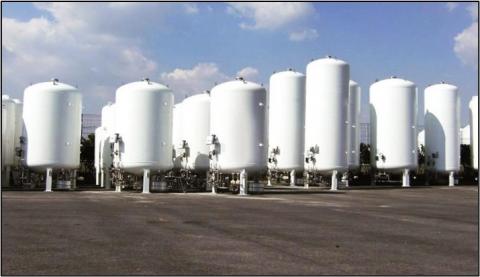
Carbon capture and storage (CCS) technology transfers CO2 emissions from fossil fuel consumption into secure geological storage [1]. CO2 capture system uses a liquid sorbent to chemically react with CO2 and form a solid material, which is then transported to a regeneration unit for decomposition. Instead of being a term, "carbon capture" in this study describes a process of capturing CO2 from a gas stream [2]. CCS involves separating CO2 from its source and storing it away from the atmosphere [3]. At present, CO2 capture systems improve energy utilization and the purity of CO2 capture [4]. CO2 capture devices use a chemical reaction to reduce carbon gas emissions [5]. Carbon capture technologies include capturing CO2 from fuel combustion or industrial processes [6]. Carbon capture units use polyethylenimine (PEI) or carbon sponges to capture carbon [7]. Carbon capture cartridges reduce CO2 emissions produced by combustion processes, such as boilers or heaters. The components and functions of CO2 capture equipment include a CO2 capture tower packed with a CO2 sorbent. However, specific information on carbon capture is not provided [8]. Carbon capture technology captures CO2 from a variety of applications and power situations [9]. Figure 1 shows a CO2 storage tank with steel walls.
Figure 1. CO2 storage tank with steel walls
Carbon capture, utilization, and storage (CCUS) technology in offshore facilities is use to reduce emissions and improve production efficiency [10]. Carbon capture is an important tool for decarbonizing the energy system and achieving global climate change targets. CO2 is captured using various industrial processes. Safe CO2 sequestration needs a dedicated measurement, monitoring, and verification program. CCS is a mitigation method, in which CO2 emissions from industrial and power production are captured and stored underground to regulate the levels of greenhouse gases in the atmosphere [11]. CO2 is captured using various devices, systems and methods to decrease CO2 concentrations in the atmosphere on a global scale [12-14].
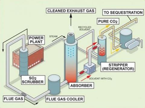
To meet climate objectives, global energy systems need to be restructured on a historic scale with ambition and speed. CCUS technologies are projected to play an important role in facilitating this transformation as part of a low-cost portfolio of technologies and tactics. Figure 2 provides a solution for significantly reducing emissions from critical industrial processes, such as the manufacturing of iron and steel, cement, and chemicals, all of which remain the foundation of contemporary civilizations. In the electricity industry, CCUS improves production diversification while addressing the risk of "lock-in" of emissions from existing infrastructure. CCUS also opens up new clean energy opportunities, such as low-carbon hydrogen production from fossil fuels for heating, transportation, and power generation. Almost all hydrogen production today is based on fossil fuels, most notably natural gas, with around 1,800 MW of output fitted with CCUS [15]. Critically, CCUS offers the infrastructure and know-how to accelerate the deployment of CO2 removal technologies, such as bioenergy with carbon capture and storage (BECCS), and direct air capture.
Figure 2. CO2 capture and sequestration
Porous materials provide a safe technique for permanent storage because they allow safer transit from industry to long-distance storage sites without leaking. CO2 stored in porous materials may be safely and easily accessed for a variety of uses.
As for events associated with possible leakage pathways, and their probability and consequences, they need to be well understood through a quantitative risk assessment process and a robust engineering design methodology. A comprehensive monitoring and verification plan can be designed as an outcome of this risk assessment analysis. The plan should define trigger points that identify conformance to or departure from agreed performance criteria. Contingency actions with a remediation plan can also be identified as part of the overall storage plan. Management and risk assessment are key components of building a CO2 storage facility and ensuring its sustainability during the project's lifetime.
If an incident occurs, the plan provide guidance for selecting a suitable site, creating project viability benchmarks in the early stages, preventing potential adverse occurrences, and designing adequate surveillance with well-thought intervention choices. It is imperative that risk assessment and management serve as efficacious channels of communication for delineating the Area of Responsibility (AOR) and for conveying the intricacies and uncertainties associated with the site, ensuring regulatory bodies' requirements are met with satisfaction.
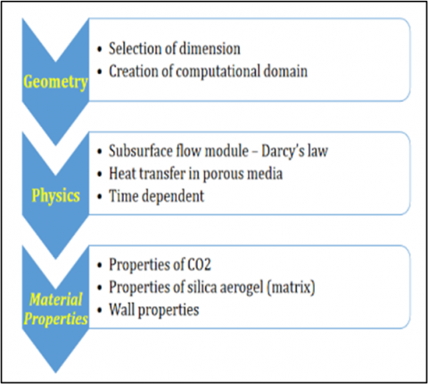
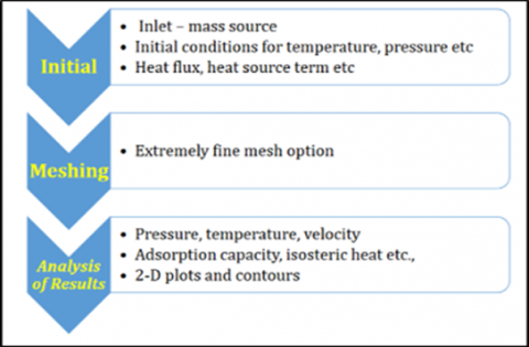
3.1 Computational domain
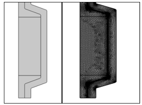
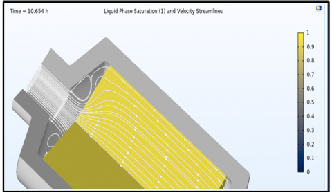
The explored domain in present simulation is restricted to the 3D part of the elbow since numerical modeling of the entire elbow demands powerful and expensive computing resources, in addition to the excessively lengthy simulation required (Figure 3).
Figure 3. Simulation required of modelling
Many models have the same fundamental operating system. Each type may be loaded with product and delivered as liquid or gas depending on the use. The next part goes into the theory underlying these procedures.
All procedures are completed using the control valves on the tank's underbelly. The valves are labeled so that they can be easily identified. The diagram and nomenclature demonstrate how the plumbing circuitry works for the specific model.
To improve tank filling, the following instructions should be obeyed:
(a)
(b)
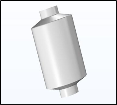
Figure 4. Computational domains (a) 2D-axisymmetric geometry, (b) 3D computational domain
Figure 4 illustrates the 2D and 3D computational domains, reflecting the dynamic nature of the simulation process, spanning from 0 to 3603 seconds. This duration encompasses CO2 gas charging (0-1200 seconds), a holding phase (1201-2401 seconds), discharge (2402-3002 seconds), and a final hold-in phase (3003-3603 seconds).
3.2 Modeling equations
The modeling equations are central to the heat and mass transport simulation for CO2 storage during the adsorption-desorption cycle in a fixed column with modified silica aerogels.
$\ { bulk }=\rho s(1-\varepsilon pellet)(1-\varepsilon b e d)$ (1)
To absorb CO2 efficiently, the adsorption bed should have sufficient porosity to allow for diffusion and free gas exchange. The bed should ideally have a large capacity to catch more CO2 every mile. The bigger this capacity, the more effective the adsorption bed is, assuming all other variables remain constant (as shown in Table 1).
$q\, {CO}_2 \ { compoun }=\ {mCO}_2 \ { sorbed \,to } \frac{\ { compound }}{\ { mcompound }}+\ {V} \cdot \ {\rho gasCO}_2$ (2)
$\begin{aligned}
& \rho {CO_2}= \ {qCO_2} \ { compound } \cdot \rho { bulk }+ \ { pgasCO_2 } \
\cdot(1-\ { εbed }) \ { εpellet }
+ \ { pgasCO_2 } \ { εbed }
&
\end{aligned}$ (3)
$n_a=n_{\text {max }} \exp \left[-\left[\frac{R T}{\varepsilon}\right]^m {\ {ln }} \left(\frac{P_0}{P}\right)^m\right]$ (4)
$\varepsilon b e d=a+\beta T$ (5)
Table 1. The specific conditions of heat flux
|
$\mathbf{n}_{\max }\left(\operatorname{mol~kg}^{-1}\right)$ |
$\alpha\left(\mathrm{J}\, \mathrm{mol}^{-1}\right)$ |
$\beta\left(\mathrm{J} \,\mathrm{mol}^{-1} \mathrm{~K}^{-1}\right)$ |
$\mathbf{P}_{\circ}(\mathbf{P a})$ |
|
5.714 |
3000.1 |
177.46 |
5.0001E8 |
3.2.1 Conservation of momentum
Darcy's flow model predicts the total pressure distribution over time, yielding a time-dependent velocity field distribution.
Darcy's law, along with the continuity equation, produces mass and momentum conservation [16].
$\frac{\partial}{\partial t}\left(\varepsilon_b p c o_2\right)+\nabla \cdot\left(p c o_2 u\right)=Q_m$ (6)
$u=-\left(\frac{K}{\mu}\right) \nabla P$ (7)
$Q_m=-M c o_2\left(1-\varepsilon_b\right)$ Psilica $\frac{\partial n_a}{\partial t}$ (8)
where, $\varepsilon_b$ represents the porosity of the adsorbent bed, $p \mathrm{co}_2$ is the fluid density, $u$ is the Darcy velocity of CO2, $K$ is the permeability (m2), $\mu$ is the dynamic viscosity of the fluid, $Q_m$ is the mass source term that accounts for the mass contributed from the gas stage to the absorption phase in the form of volume per second, Psilica represents particle density, Mco2 is the molecular volume of CO2 gas.
Some significant hurdles must be addressed concurrently in order to achieve these traits. A large amount of adsorption bed is necessary to offset the high CO2 emissions, which is one of the hurdles. It is significantly difficult because it is relatively expensive to build such a bed. Another hurdle is to attain reusability, selectivity, and high capacity simultaneously.
3.2.2 Energy conservation
The heat of the system is transported during the CO2 adsorption process in porous medium via conduction and convection. The energy balance partial differential equation (PDE) can be expressed as follows [17]:
$\begin{aligned}
\frac{\partial}{\partial t}\left(\varepsilon_b p c o_2\right)+\nabla \cdot & {\left[p \operatorname{co}_2\left(-\frac{k}{\mu} \nabla P\right)\right] }
=-M \operatorname{co}_2\left(1-\varepsilon_b\right) {\text{P}silica } \frac{\partial n_a}{\partial t}
\end{aligned}$ (9)
$q_{s t}=\alpha \sqrt{\ln \left(n_{\max } / n_a\right)}$ (10)
$\begin{aligned}
& \left(\varepsilon_b p c o_2+p c o_2 n_a \ {Mco}_2 \ {Cpg}+\ {\text{P}silica} \,\ {Cps}\right) \frac{\partial T}{\partial t} +\mathrm{pcO}_2 \ {Cpg} \overrightarrow{\ {v}} \text {. } \nabla \ {T} =\nabla \cdot\left(K_{\text {eff }} \nabla T\right)+Q+\emptyset
&
\end{aligned}$ (11)
$K_{\text {eff }}=\varepsilon_b K c o_2+\left(1-\varepsilon_b\right) K_{\text {silica }}$ (12)
$\begin{aligned}
Q=Q_a+Q_p= & \left(1-\varepsilon_b\right) \, {{\text P}silica} \frac{\partial n_a}{\partial t} q_{s t} +\gamma T\left[\varepsilon_b \frac{\partial p}{\partial t}+(\vec{v} \cdot \nabla) \mathrm{p}\right]
\end{aligned}$ (13)
where, $C p g$ is the specific heat capacity of $\mathrm{CO}_2, v$ is the Darcy velocity, $K_{\text {eff }}$ is the effective thermal conductivity, $Q$ is the energy source, including adsorption, $Q_a$ is the heat source, and $Q_p$ is the compression, $q$ is the esoteric heat of adsorption, and $\Phi$ is the viscous dissipation term. The volumetric thermal expansion coefficient $(\gamma)$ for ideal gases is characterized by the reciprocal of the temperature $(1 / \mathrm{T})$, denoted in inverse Kelvin.
To prevent CO2 leakage, the adsorption bed should be reusable at least 1000 times. This ensures that CO2 can be captured back. At the same time, the sorbent should be inexpensive to create, reducing the complexity of building an adsorption bed and allowing it to be widely used.
The adsorption bed should be able to continue absorbing CO2 despite unexpected temperature, humidity, and pressure changes. An ideal sorbent should trap CO2 with unlimited selectivity.
3.2.3 Boundary and initial conditions
The initial pressure within the system is set at 0.1 MPa. The velocity of the gas entering the system is maintained at 0.15 m/s. The initial temperature within the storage tank is established at 323 K, matching the inlet gas temperature. The heat flux across the boundary is $-h_t^*\left(T_{a m b}-T\right)$, where $T_{a m b}$ represents the ambient temperature, set at 293.15 K, and $h_t$ is the heat transfer coefficient, valued at 36 W/m²K.
Many researchers have discussed various novel methodologies and approaches used in CO2 storage and capture. In some studies, CO2 capture systems utilize air blowers, absorption towers, heat pump systems, and solution heat exchangers to improve energy utilization and capture efficiency. In other studies, CO2 recovering systems use a phase-changing liquid sorbent and a dry transport mechanism, which allows for the decomposition of the solid material to release CO2 gas and regenerated liquid sorbent. These studies have also discussed technological developments and improved techniques that reduce the cost of carbon capture. Monitoring stored CO2 is the key, which contributes to the widespread commercial deployment of carbon storage and capture.
This study proposes a way and device which can collect CO2 from the gaseous phase with an absorbent of a liquid state. The sorbent chemically reacts with CO2 to form a solid phase, which in turn can be decomposed in a regeneration unit to release CO2 gas and regenerate the liquid sorbent. The technique, in turn, does not incorporate the use of a carrier liquid. Contrary to that, the dry screw pump method is employed to navigate through the solid materials from a reaction zone to regeneration unit at a higher pressure. The solid material is burned in the regeneration unit to decompose, followed by the gas release, and also liquid sorbent regeneration. Furthermore, this study develops a method of separation and recovery of CO2 from a gas stream using a gas/liquid phase-changing sorbent and a dry-based driving mechanical device.
Such a balancing valve between the gas phase substance in the storage drum and the condenser intake means that the tank prevents any high-pressure buildup. In addition, the tank is designed to operate efficiently when supercritical CO2 fluid is transporting that means it can endure the highly pressurized supercritical fluids. While no particular pressure data is supplied, it may be assumed that the tank is intended to function within acceptable pressure limits to allow successful CO2 storage and recycling. It should be noted that the sources cited do not give detailed information regarding the pressure levels and temperatures of the CO2 storage tank.
This study focuses on the tank's design and features, including the CO2 input, balance controlling valve, tempered or quartz glass liquid level meter, and heating equipment. Positioned at the bottom or side wall of the tank body, the heating device can be used as an electrical heating pipe or a heat exchanger, suggesting that it is used to regulate the tank's temperature.
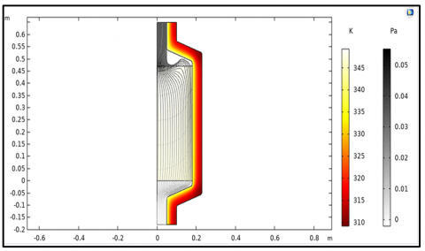
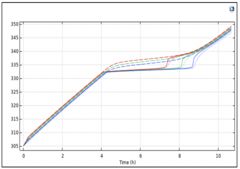
Figure 5 delineates the pressure within the tank at critical junctures: post the charging phase at 1200 seconds and following the discharging phase at 3002 seconds. Figure 6 elucidates the surface temperature and visualizes the Darcy velocity field across the surface, employing arrow notation for directionality. The color gradient in Figure 6 signifies the acute incidence angle, measured in degrees from the surface normal.
Figure 5. Pressure (Pa) at the end of charging (1200 seconds) and discharging (3002 seconds)
Figure 6. Surface temperature (K); arrow surface for the Darcy's velocity field
Figure 7. Variation temperature on carbon captures walls
Due to thermal impacts, higher flow rates result in minimum adsorption at the exact charging pressure. As a result, efforts to increase heat transmission should be implemented, such as enhancing the storage bed's thermal conductivity. In terms of storage capacity, fast hydrogenation is achievable, making such systems suitable for on-board hydrogen storage based on activated carbon adsorption.
Figure 7 shows the variation temperature on carbon captures walls, which has been modeled utilizing the Finnie model. To investigate the effect of flow rate on the performance of the energy storage unit, a sensitivity analysis was performed by increasing the fill flow rate by two and four times while keeping the discharge flow rate the same. The simulation results are shown in Figure 6.
Eq. (6) obtained at the same load shows that the peak temperature and pressure increase, and the dynamics become faster as the flow rate increases.
Iraq is recognized as a country heavily reliant on fossil fuels for electricity generation, positioning it among the leading oil-producing nations. This reliance contributes significantly to the emission of CO2 and other greenhouse gases, exacerbating the effects of climate change and posing substantial risks to human health through associated diseases. In response to these challenges, there is an urgent need for immediate strategies to mitigate emissions, aligning with the nation's production capacity and infrastructure capabilities. In some countries, natural fuel has been replaced by gas.
CCS is considered one of the modern technologies to reduce pollution and move towards a sustainable environment. This technique encompasses multiple phases, which have been examined in this study. It is designed to be compatible with the carbon emissions, which, upon being captured, generate heat. This heat, in turn, has been identified as a potential energy source. Although it is not possible to eliminate all carbon emissions at one time, with the passage of years and the expansion of the storage process, carbon neutrality can be reached. Thus, the storage phase is discerned to offer dual benefits: it facilitates the containment of carbon in tanks, thereby mitigating carbon emission pollution, and it generates heat, which is harnessed as an energy source. Further findings from this study include:
The study discusses a CO2 storage tank, which is augmented by an intake mechanism linked to a condenser. This configuration facilitates the regulation of pressure within the tank and amplifies the CO2 recovery rate. Heating devices, such as pipes or heat exchangers, are added to either the bottom or side walls of the tank. These heating mechanisms ensure that supercritical CO2 fluid flows smoothly and efficiently.
Improving CCS projects involves reducing costs associated with carbon capture and enhancing carbon monitoring techniques. The installation of CCS technologies, where feasible, has been identified as a straightforward method to improve efficiency. Energy penalties and costs can be lowered to make those systems more economically viable. The key to raise carbon capture capacities is either combining adsorbents or creating new materials. The only question is how the carbon pricing and compliance mechanisms would work without these regulations and carbon pricing being carried out properly as that would most likely contribute to this research being forgotten.
What it covers finally is an incorporated tempered or quartz glass level meter. The meter is very precise having made the measurement of the CO2 concentration somewhat easy. Moreover, the tempered version of the watch is resistant as well and you can apply rough conditions to the quartz without having it break. Actually, though carbon dioxide is more popularly known as a greenhouse gas, these gas tanks are astounding for CO2 recycling as well as storage. Furthermore, for the purposes of a CO2 extraction system and a liquid level meter, be it tempered or made of quartz glass, they can be used to hold a constant level of CO2 in the tank.
The use of such heating equipment, like electrical heating line passing through a heat exchange system, means that the tank functions excellently and has the ability to send the required supercritical CO2 fluid flow. The success of the study is indicated by CO2 storage and application techniques, supercritical CO2 fluid enhanced tracking capabilities, and the versatility in application design. In a nutshell, the research is about the CO2 storage tank which is confronted with significant advantages in the supercritical CO2 recycle processing and storage but together with supercritical fluid extraction system. An inlet along with a companion compressor doused in a vapor chamber that works along with a pressure regulator and CO2 recovery rate booster to improve the performance of the system.
[1] Gibbins, J., Chalmers, H. (2008). Carbon capture and storage. Energy Policy, 36(12): 4317-4322. https://doi.org/10.1016/j.enpol.2008.09.058
[2] Tiffany, Elizabeth, Pinard, Westendorf., Sarah, Elizabeth, Genovese., Teresa, Grocela-Rocha., Robert, J., Perry., Benjamin, Rue, Wood. (2011). Carbon dioxide capture system and method of capturing carbon dioxide. https://www.researchgate.net/publication/302730574_Carbon_dioxide_capture_system_and_methods_of_capturing_carbon_dioxide
[3] Underschultz., J., Dodds, K., Michael, K., Sharma, S., Wall, T., Whittaker, S. (2016). Carbon capture and storage. In Sustainability in the Mineral and Energy Sectors, pp. 16. https://doi.org/10.1201/9781315369853-23
[4] Wang, X.L., Zhang, F.Y., Li, L.F., Zhang, H., Deng, S. (2021). Chapter seven - carbon dioxide capture. Advances in Chemical Engineering, 58: 297-348. https://doi.org/10.1016/bs.ache.2021.10.005
[5] Keith, D.W., Holmes, G., Angelo, D.S., Heidel, K. (2018). A process for capturing CO2 from the atmosphere. Joule, 2(8):1573-1594. https://doi.org/10.1016/j.joule.2018.05.006
[6] Darabkhani, H.G., Varasteh, H., Bazooyar, B. (2023). 2 - Main technologies in CO2 capture. Carbon Capture Technologies for Gas-Turbine-Based Power Plants, 19-38. https://doi.org/10.1016/B978-0-12-818868-2.00002-3
[7] Guo, L., Yuan, H., Zhang, D., Zhang, J., Hua, Q., Ma, X., Chen, K. (2020). A multi-center, randomized, double-blind, placebo-parallel controlled trial for the efficacy and safety of shenfuqiangxin pills in the treatment of chronic heart failure (Heart-Kidney yang deficiency syndrome). Medicine, 99(21): e20271. https://doi.org/10.1097/MD.0000000000020271
[8] Haszeldine, R.S. (2009). Carbon capture and storage: How green can black be? Science, 325(5948): 1647-1652. https://doi.org/10.1126/science.1172246
[9] Hiyoshi, N., Yogo, K., Yashima, T. (2008). Adsorption of carbon dioxide on amine-modified MSU-H silica in the presence of water vapor. Chemistry Letters, 37(12): 1266-1267. https://doi.org/10.1246/cl.2008.1266
[10] Ngu, L.H. (2022). Carbon capture technologies. Reference Module in Earth Systems and Environmental Sciences. https://doi.org/10.1016/B978-0-323-90386-8.00028-0
[11] Moretta, D.D., Craig, J. (2022). Carbon capture and storage (CCS). EPJ Web of Conferences, 268(26). https://doi.org/10.1051/epjconf/202226800005
[12] English, J.M., English, K.L. (2022). An overview of carbon capture and storage and its potential role in the energy transition. First Break, 40(4): 35-40. https://doi.org/10.3997/1365-2397.fb2022028
[13] Canino, R. (2021). Carbon capture systems and methods. US10603625B1, Washington, DC: U.S.
[14] Thomas, J.V., Joy, J., Narayanankutty, G.K. (2022). A method for capturing carbon dioxide. US20220370955A1, U.S.
[15] Singh, S.P., Ku, A.Y., Macdowell, N., Cao, C. (2022). Profitability and the use of flexible CO2 capture and storage (CCS) in the transition to decarbonized electricity systems. International Journal of Greenhouse Gas Control, 120:103767. https://doi.org/10.1016/j.ijggc.2022.103767
[16] Shi, Y., Huang, X.C., Feng, G.H. (2019). Wellbore-reservoir coupling simulation of geochemical reactions involving carbon dioxide. International Journal of Heat and Technology, 37(3): 811-819. https://doi.org/10.18280/ijht.370318
[17] Noh, H., Kang, K., Huh, C., Kang, S., Seo, Y. (2018). Identification of potential hazardous events of unloading system and CO2 storage tanks of an intermediate storage terminal for the Korea clean carbon storage project 2025. International Journal of Safety and Security Engineering, 8(2): 258-265. https://doi.org/10.2495/SAFE-V8-N2-258-265