Hamed A. Al-Falahi![]()
© 2023 IIETA. This article is published by IIETA and is licensed under the CC BY 4.0 license (http://creativecommons.org/licenses/by/4.0/).
OPEN ACCESS
This study focuses on the modification and thermal analysis of eight distinct carbon-carbon (C/C) composite types, designed as advanced thermal insulators. The investigation proceeded along two primary pathways. Firstly, an examination was conducted on the impact of phenolic resin modification, aimed at diminishing the erosion rate of these composites when exposed to an oxyacetylene flame. This involved integrating ammonia molecules with nickel ions in a complex, facilitating hydrogen-oxygen bonding, as evidenced by the pronounced broad band of hydroxyl (OH) groups in Fourier-transform infrared spectroscopy (FTIR) results. The presence of this nickel complex was observed to accelerate the graphitization level (GL). Secondly, a comprehensive thermo-mathematical analysis was undertaken on C/C models subjected to oxy-acetylene flames, utilizing the Finite Element Method (FEM) as simulated via the ANSYS software package. X-ray diffraction analysis conducted at 1650℃ revealed the presence of both graphite and turbostratic structures, designated as T&G. This signifies an enhanced GL in resins modified with 10 wt.% of the nickel complex Ni(CH2COCH2COCH3)2.2NH3, compared to those with 3 and 5 wt.% modifications. The effectiveness of modified C/C composites was found to be contingent on the specific type of additive and reinforcement used. Furthermore, a notable convergence between practical and mathematical analysis results was observed, establishing a reliable database for optimizing the selection of insulation type and thickness in practical applications. This investigation underscores the significance of chemical modifications in enhancing the thermal insulation properties of C/C composites. The findings hold substantial implications for the development of high-performance insulation materials, particularly in contexts demanding resistance to extreme temperatures and erosive environments.
ablative composites, thermal analyses, catalytic graphitization, oxy-acetylene flame
C/C composites bonded to a modified phenolic resin have been important materials for many years as thermal protection systems for a variety of advanced industries, particularly the military and aerospace. Phenolic resins (PRs) based on phenol and formaldehyde have been widely used in the manufacture of various parts of automobiles [1], thermal insulators with high performance as thermal ablative materials especially in aerospace and aircraft [2-4], in industrial tunnels [5]. It is an important material in high-technology applications, because of its high reliability, structural integrity, thermal stability, and resistance to chemical media [6, 7]. Thermal protection systems used in conditions of re-entry require that these systems bear a very high temperature that may exceed 2000 K and a high-temperature gradient, in addition to withstanding shock waves [8]. Carbon/carbon composites are the best choices for meeting special requirements due to their outstanding physical properties Such as low density and coefficient of thermal expansion, outstanding thermo-mechanical properties, and high resistance to ablation. [9, 10].
Atmospheric re-entry systems require the use of carbon/carbon composites and simulation of the ablation process that they are exposed to through peeling off of the insulating layers as a result of friction with air molecules at high speed and is accompanied by a series of physical changes such as radiation, convection, diffusion, and complex chemical reactions such as phase changes [11, 12]. More recent research on ablation resistance has focused on ceramic materials such as silicon carbide, zirconia, zirconium, boron nitride, boron, etc. due to their high melting points. [13-15]. However, its complex manufacturing technology prevents these materials from being widely used [16]. Other studies focused on service conditions such as flame velocity and temperature, some of them focused on bulk density and carbon fiber performance, etc. and all of them have a significant impact on the ablation process of C/C composites [17, 18]. Other researchers have studied the addition of a certain amount of metal carbides such as hafnium carbide, zirconium carbide, and tantalum carbide to C/C composites in order to ensure that the high service temperature is exceeded [19-21].
Evaluation of the thermal insulation and ablation resistance of phenolic carbon nanocomposites modified with silica and titanium oxides has been completed in other studies. The results showed excellent mechanical properties, good thermal insulation, remarkable thermal stability, low ablation resistance between 0.004 and 0.003 mm/s, and a mass loss rate as low as 0.006. and 0.009 g/s at heat fluxes of 1.0 and 1.5 MW/m2 [22]. Choosing boric acid and zirconia as modifiers to successfully prepare a new ceramic resin with the hybridization of B-Si-Zr, which are considered inorganic materials that were introduced into phenol-formaldehyde resin and thus contributed to modify thermal insulation properties of fiber-reinforced composites [23]. There is another study that focused on improving the ablation resistance of phenolic composites by building a nanostructured char layer through the catalytic graphitization of nickel-boron-modified phenolic resin, and the results showed that the linear and block ablation rates of CLBPR decreased by 128.9% and 32.6% [24, 25].
The catalytic graphitization of carbon/carbon compounds was also studied by lanthanum oxide, as the results showed that La2O3 promoted the formation of more perfect and larger crystals, and improved the electrical and mechanical properties of carbon/carbon compounds [26]. Both boric acid, nickel complex, and Chromium complex have been studied for their effect on accelerating the phenol-formaldehyde resin graphitization process, the results showed that the presence of boron ion in boric acid allowed boron-oxygen bonding with the oxygen of the polymer and that the presence of ammonia molecules with the nickel complex allowed hydrogen bonding with to polymer oxygen, On the other hand, the Cr (C5H7O2)3 form adducts with polymers containing functional groups such as phenols and the results showed a high degree of graphitization [27, 28]. The best graphite level of 73% and the highest amount of graphite carbon of 48% were achieved when adding 10% by weight of boric acid to the phenol-formaldehyde resin produced with 20% by weight of lignin [29].
The evaluation of thermal decomposition in graphite and carbon black phenolic compounds has been conducted, leading to the conclusion that controlled chemical modifications can enhance the performance of carbon atoms, thereby increasing the char yield from phenolic resin products [30]. Furthermore, studies have demonstrated that carbon/carbon composites, when modified with a layer of zirconium boride (CBCFs/ZrB), exhibit significant alterations in their ablation behavior and microstructure under high-temperature oxyacetylene flame conditions. Notably, the molten SiO from the coating permeates into the CBCFs/ZrB composites, acting as an efficient barrier against the oxidation of the carbon fibers within these composites [31]. Additional research has focused on examining the one-directional ablation rate and ablation microstructure under an oxyacetylene flame. This included measuring the temperature distribution on the surface and subsurface of the model using optical pyrometers and thermocouples. The experimental findings indicated superior ablation resistance in C/C composites, followed by C/C hybrid composites, with graphite exhibiting the least resistance [32]. These studies collectively highlight the resistance of various ceramic materials and C/C composites to ablation and oxidation, as well as their thermal-mechanical properties. There is also an emphasis on the enhancement of the graphitization level in C/C composites through the use of ceramic materials, complexes, and metal oxides.
The present study aims to explore the influence of a nickel organometallic compound on the graphitization level of novolac under oxy-acetylene flame conditions and to assess the ablation rate of its C/C composites. This involves both practical and theoretical evaluations based on the FEM, simulated using the ANSYS software package. The novel aspect of this research lies in verifying the bonding of the laboratory-prepared nickel complex metal to the novolac polymer molecule. This is anticipated to improve the ablation rate of C/C composites, thereby contributing to the development of a comprehensive database. Such a database is envisaged to serve as a guide for thermal insulator designers in selecting appropriate insulators with the ideal thickness for practical applications.
2.1 Material and specimen preparation
Non-modified novolac resin (NV0) was prepared by reacting phenol with formaldehyde. The reaction takes place in a batch reactor. Phenol, formalin, and acid are mixed. The acid is either hydrochloric acid with 0.1-0.32wt.% of phenol or oxalic acid with a weight percentage of 0.5-2wt.%. Then the mixture is heated at about 105℃, and the heating continues for 2-4 hours until the resin becomes hydrophobic. water and the mixture appears cloudy. The water is then distilled at atmospheric pressure at a temperature of 140-150℃. As a result, we obtain a colorless, solid, and brittle product characterized by IR technology.
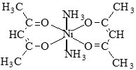
Diamine Nickel Acetylacetonate [Ni (acac)2.2NH3] is used as an accelerator for the graphitization process of the char layer under the influence of the oxy-acetylene torch. It was laboratory-prepared and examined by FT.IR. in a previous study [27].
Modified novolac resin (NVm) was prepared by charging the reaction vessel with 17.54 g of novellas resin and 1.8 g of Ni (CH2COCH2COCH3)2.2NH3, the reaction mixture was stirred manually for 45 minutes at a temperature ranging from 120 to 135℃, a solid, deeply colored polymer was obtained. The product is crushed and dissolved in water to remove unreacted nickel complex, and finally, the product is dried and examined using FT.IR technology.
To evaluate the effect of the nickel complex Ni (CH2COCH2COCH3)2.2NH3 on the graphitization process with an oxy-acetylene torch, as a first stage, different percentages of the nickel complex 3, 5, and 10% by weight were added to nonmodified novolac resin ground to 100 mesh, then the solvent is added with continuous mixing in order to ensure the homogeneity of the mixture, then the mixture is heated to 80℃ to ensure the evaporation of the solvent. The mixture was poured into a cylindrical rubber mold (40×25 mm), then the samples were dried at 100°C for two days. The resulting resin block was initially calcined at 800℃ at a rate of 5℃/min under an inert atmosphere by placing the samples in an alumina crucible covered with a mixture of carbon black and silica to ensure that the models did not oxidize. The second stage is in which the resin samples prepared in the first stage are burned with an oxy-acetylene torch to 1650℃. Novolac standard samples were prepared without any additive to be used as a reference (see Table 1).
Table 1. Resin systems prepared
|
Sample No. |
Sample Code |
Novolac Content (wt.%) |
Additive Content (wt.%) |
|
1 |
NV0 |
100 |
0 |
|
2 |
NV1 |
97 |
3 |
|
3 |
NV2 |
95 |
5 |
|
4 |
NV3 |
90 |
10 |
By examining the XRD related to graphitic or non-graphitic carbon, the graphitization level of the compositions is determined by the area under the curve according to the following equation [33].
$G L \%=\frac{A_{g r . C}}{A_{\text {total }}} \times 100 \%$ (1)
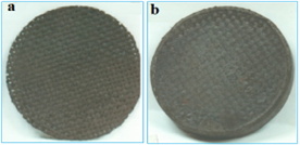
Carbon cloth composites were prepared, as the first stage, needs preparation of (prepregs) by impregnating the fibers with the resin, solvent, and filler, then the latter is converted into the second stage, by heating at 70℃ for several minutes, as shown in Figure 1(a). Finally, the laminates for the property determinations are cut to the proposed size and then molded by hot-pressing at a temperature of 160℃ and pressure of 10 MPa, to a density of about 1425±25 kg/m3 as shown in Figure 1. Curing time ranges from 20 to 30 minutes [34].
Carbon chopped phenolic composites were prepared by mixing the filler, solvent, and short fiber 5 mm long into modified phenolic resin such that the fibers are randomly oriented. The material is cured at 70℃ for 15 minutes and subsequent preparation of composites is by hot-pressing the stacks at 10 MPa and 160℃ for 20 minutes. During this procedure, the fiber becomes partially oriented in directions normal to the applied pressure [35].
Special specimens were prepared to evaluate the ablation rate with the oxy-acetylene torch in the form of discs consisting of many layers as shown in Figure 1(b). The test samples were 60 ± 71 mm in diameter and 6 ± 0.41 mm in diameter for all tests as shown in Figure 1. An average of three measurements was taken to reduce the error rate.
Figure 1. (a) Ablative specimen before test, (b) one layer of carbon cloth prepreg Stack phenolic composite sheet
2.2 Characterization of devices
In this study, an XRD model PW1877 to evaluate Graphitization level, and FTIR model 8300 to evaluate frequencies of modified resins, were used. An experimental system designed for an oxy-acetylene burner was designed according to ASTM No. E 285-80, K-type thermocouples, a Disc Lee conductivity tester, a laptop computer, an ANSYS “10” software package, and a set of laboratory tools.
2.3 Ablative test technique by oxy-acetylene flame
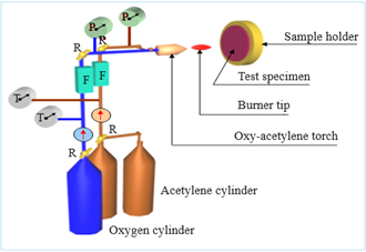
The ablative tests were performed according to the ASTM No. E 285-80. The experiment setup is shown schematically in Figure 2. The apparatus consists of an oxyacetylene flame, a specimen holder, a torch tip has a single port of 0.33 cm, accurate flowmeters for the flow of gases, pressure regulators, flow pressure gauges to monitor gas pressure, and needle valves to mix perfect ratio of oxygen and acetylene.
The experiment was carried out by means of lighting the flame and adjusting the gas flow rate until the flame was stabilized and had a blue conical shape with a height of 30 mm. The test specimen was placed at an 18.7mm distance from the torch tip. Hot gases were directed at an angle of 90o to the specimen surface center until burn-through was achieved as shown in Figure 2. Three replicates of each specimen were tested to reduce error.
The erosion rate for each replicate was calculated by dividing the original thickness of the specimen by the time to burn through as follows:
$E_r=\frac{d}{b}$ (2)
Figure 2. Schematic diagram of ablative test. (R) regulator pressure; (F) flowmeter; (P) pressure gauge; (T) thermometer
Average erosion rate is calculated by dividing the sum of individual values of erosion rates by the number of replicates;
$E_{r, \text { avrage }}=\frac{\sum E_r}{N}$ (3)
The insulation indices for each replicate were calculated by dividing the time for the back face temperature to reach 204℃ (from ambient) by the original thickness of the specimen.
$I=\frac{t_T}{d}$ (4)
The average insulation index can be calculated by dividing the sum of individual values of insulation indices at temperature (T) by the number of replicates:
$I_{\text {arg }}=\frac{\sum I}{N}$ (5)
The charring rate for each replicate was calculated from the reciprocal of the insulation indexes as follows:
$C_R=\frac{1}{I}$ (6)
The average char rate Cravg can be calculated from the following equation;
$C R_ {avg}=\frac{1}{I_{avg}}$ (7)
3.1 Nickel complex effect on the graphitization level of novalac by oxy-acetylene flame
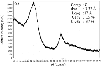
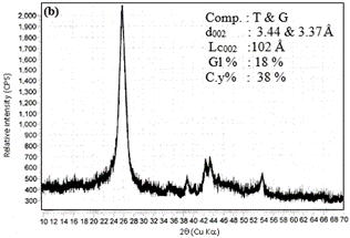
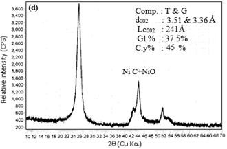
Figure 3 shows the X-ray results of novalac with 3, 5, and 10 wt% of Ni(CH2COCH2COCH3)2.2NH3, at 1650℃ under the oxy-acetylene flame, and when compared with the profiles of the OM-free samples heat-treated at 1650℃ (Figure 3(a)), an additional peak was shown to appear above that of the T component. This peak is well known to be caused by the graphite structure (G-component) and had d002 = 3.37 Å and Lc002 = 102 Å for the lowest concentration of 3 wt% nickel complex (Figure 3(b)), while samples containing concentrations of 5 and 10 wt% exhibit a more graphitic structure corresponding to layer spacings of 3.361 and 3.360 Å and Lc002 = 164 Å and 241 Å as in Figures 3(c) and 3(d), respectively. The above results suggest that this crystalline formation might be due to the presence of NixC, crystals. This may preliminarily act as a nucleating agent or the carbon atoms may build a more stable turbostratic crystalline structure benefiting from the similarity of their respective crystal structures. At higher temperatures above 1650℃, the metal carbides are expected to decompose, when the metal atoms then leave the G and T components behind. The most reliable parameters are shown in Table 2.
Table 2. Most reliable parameters at different concentrations
|
d(M) (Å) at Various Temperatures and Concentrations (%) |
d(ASTM) (Å) |
(I/Ii) ASTM |
hkl |
Component |
||||
|
|
0% |
3% |
5% |
10% |
||||
|
|
3.71 |
- |
- |
- |
3.71 |
40 |
201 |
C |
|
|
2.10 |
- |
- |
- |
2.10 |
40 |
304 |
C |
|
|
1.91 |
- |
- |
- |
1.91 |
20 |
401 |
C |
|
|
- |
3.44 |
3.41 |
3.51 |
- |
- |
- |
T |
|
|
- |
3.37 |
3.36 |
3.36 |
3.35 |
100 |
002 |
G |
|
|
- |
2.11 |
2.11 |
2.11 |
2.13 |
2 |
100 |
G |
|
|
- |
1.67 |
1.67 |
1.67 |
1.68 |
8 |
004 |
G |
|
|
- |
2.41 |
2.41 |
2.41 |
2.41 |
91 |
111 |
NiO |
|
|
- |
2.08 |
2.08 |
2.08 |
2.08 |
100 |
200 |
NiO |
|
|
- |
2.03 |
2.03 |
2.03 |
2.03 |
100 |
111 |
NixC+Ni |
|
|
- |
1.76 |
1.76 |
1.76 |
1.76 |
80 |
200 |
NixC+Ni |
|
|
- |
1.24 |
1.24 |
1.23 |
1.25 |
60 |
022 |
NixC+Ni |
|
Lc, Å |
17 |
102 |
164 |
241 |
- |
- |
- |
- |
|
Gl % |
1.5 |
18 |
31 |
37.5 |
- |
- |
- |
- |
|
C.y % |
37 |
38 |
40 |
45 |
- |
- |
- |
- |
(Gl) graphitization level, (C.y.) Percent of carbon char result at 1650℃
Based on the results discussed above, which indicated that the nickel complex has a clear effect on the acceleration of the graphitization of novalac, which indicates that the C/C composites prepared from the modified resins will give much better control of the properties in the high-temperature behavior.
3.2 Spectroscopy characterization by FT.IR
Ni(acac)2.2NH3 was laboratory prepared and examined by FT.IR. in a previous study [27]. The results indicated the spectrum of nickel complex exhibited clear bands at 3080 cm-1, related to the olephenic (C–H) band, 2093.9 cm–1 related to the Aliphatic (C-H) band, and another absorption band at 1620 cm–1 related to (N–H). Also, the FTIR spectrum of this complex gave an intense band at 420 cm–1 referring to bonding Ni with polymer oxygen, and 350 cm–1 refer to bonding between Ni and ammonia molecules.
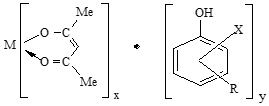
Metal acetylacetones are bound to polymers containing functional groups such as phenols. Although such reactions take place by mixing phenol, metal salt, and acetylacetone, the product is an adduct as illustrated below, this means that acetylacetonates are too stable towards ligand exchange.
where, M = Ni, X = H, R = H., x = 2 or 3, y = 1.76, 2, 2.4.
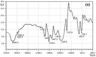
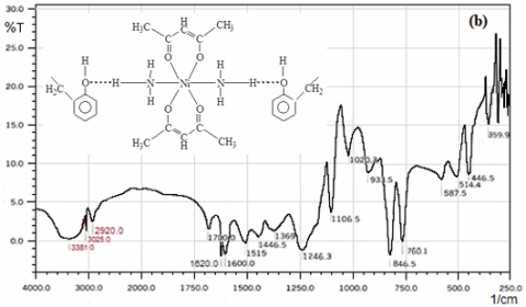
Figure 4(a) shows non-modified novolac with the chemical composition shown below, The I.R. spectra for the prepared non-modified resin in this study showed the same bands as the modified resin, except for the 1620 cm-1 and 359.9 cm-1 bands of the nitrogen-hydrogen bonding and the nickel-oxygen metal complex, respectively.
Novolac thermally modified resin is obtained by reacting with metal complexes such as nickel-acetyl acetone. This is because the metal ion is relatively highly saturated and gives covalent properties that do not allow further bonding with other atoms. Therefore, if these thermally modified resins are exposed to high temperatures, they decompose slower than conventional resins. However, the presence of ammonia molecules associated with the nickel ion in Ni(acac)2.2NH3 may allow hydrogen bonding with the oxygen of the polymer, and this was confirmed by the FT.IR spectrum as Figure 4(b) showed very broad bands at 3381 cm–1 related to v (O-H), and also an intense band at 359.9 cm-1 which was indicated to v (M-O). Based on the previous results, it may conclude that Ni(acac)2.2NH3 had a strong catalytic effect on the carbon char. The FTIR results for all bands are listed in Table 3.
Figure 3. X-ray profiles of novalac specimens containing, (a) 0 wt%; (b) 3wt%; (c) 5wt%, (d) 10wt% of Ni(acac)2.2NH3 obtained under oxy-acetylene flame at 1650℃
Figure 4. Spectra of (a) Non-modified resin (NV0); (b)Modified resin with Ni(acac)2.2NH3 (NVm)
Table 3. The frequencies of non-modified and modified resin prepared (cm–1)
|
Characteristics |
NV0 |
NVm |
Frequency Mode |
|
V.br.; S. |
3381 |
3381 |
Phenolic v(OH) |
|
W |
3025 |
3025 |
Aromatic v(CH) |
|
W |
2920 |
2920 |
Aliphatic v(CH) |
|
m |
1700 |
1700 |
v(C–O) |
|
d;S. |
1604.7 |
1600 |
v(C=C) |
|
d;S. |
– |
1620 |
$\delta$(N–H) |
|
S. |
1510.2 |
1515 |
v(C=O) |
br.= Broad; d = Doublet; m = Medium; sh= Shoulder; V= Very; W=Weak
3.3 Ablative properties of C/C phenolic composites at oxy-acetylene flame
Based on the results obtained in Figures 3 and 4 and Tables 2 and 3, which indicated the selection of the NV3 model with weight ratios of 10% of the nickel complex and 90% of the Navolac resin as the best models in accelerating the graphitization process. At the same complex ratio, a developed polymer NVm was obtained by chemical reaction. So, models of carbon composites are proposed in Table 4.
This section represents the experimental results obtained from ablative testing of novolac resin composites under an oxy-acetylene flame, as determined in Figure 2. Eight sets of different composite systems were prepared in the present work with a fixed thickness of about 6 mm. The flame test indicated that the erosion rate exhibited by various composites varied strongly as shown in Table 4. The results were based on the following observations;
a. Composites C4 and C8 show the lowest erosion rate, and higher insulation index, taking into account the filler and resin ratio as well as the type of fiber. The high percentage filler NV3 and modified novolac resin NVm acted as a balancing agent for the thermo-mechanical properties of the composites. The reason for this is attributed to the fact that the chemical reaction between the organometallic compounds and novalac plays an important role because of the observed distinct bands, especially those associated with δ(NH) and (MO)v, which makes their decomposition slower than the conventional resin, and this is also attributed to the metal carbide particles present on the surface of the carbon particles as shown by the X-ray analysis in Figure 3, the nickel carbides are diffused in the inner part of the carbon particles leaving the G and T components behind and thus preventing the carbon material from oxidizing and reduce rate of decomposition of resin in composites at elevated temperature in the course of heat treatment under an oxy-acetylene flame.
b. The G and T structures also play an important role in improving the thermal properties of the charring carbon to resist erosion caused by gas flow stresses. it gives a high carbon yield of up to 45% which is reflected in the increase in the charring layer which protects the virgin zone of composites from hot gas. At the same time, it will act as a mechanical stabilizer for the porous charred layers and keep them intact. Thus, it will hinder the erosion rate and thus enhance the insulation process by maintaining the thickness of these layers.
c. The erosion rate of plain-woven phenolic composites (2DC) is much lower than that of chopped fiber composites (CCF) because it has excellent shear strength and low density compared to chopped-strand carbon fiber. On the other hand, the random nature of the chopped fibers may cause the heat to be diverted in different directions, both parallel and perpendicular to the fibers. As expected, the conductivity values are at least twice as high as those of normal woven phenolic composites as shown in Table 5.
Table 4. Effect of type of filler on the ablative and physical properties under oxy-acetylene flame at 1650℃
|
Group |
Composite Code |
Matrix (40 wt. %) |
Reinforcement (60 wt. %) |
Thickness (mm) |
Time to Burn Through (sec) |
Erosion Rate (mm/sec) |
||
|
NVm (wt%) |
NV3 (wt%) |
S(*) wt% |
||||||
|
A |
C1 |
34.4 |
4 |
1.6 |
2DC |
6 |
39 |
0.153 |
|
C2 |
33.6 |
4.8 |
1.6 |
2DC |
6 |
44 |
0.136 |
|
|
C3 |
32.8 |
5.6 |
1.6 |
2DC |
6 |
52 |
0.115 |
|
|
C4 |
32 |
6.4 |
1.6 |
2DC |
6 |
72 |
0.080 |
|
|
B |
C5 |
34.4 |
4 |
1.6 |
CCF |
6 |
36 |
0.166 |
|
C6 |
33.6 |
4.8 |
1.6 |
CCF |
6 |
40 |
0.150 |
|
|
C7 |
32.8 |
5.6 |
1.6 |
CCF |
6 |
46 |
0.130 |
|
|
C8 |
32 |
6.4 |
1.6 |
CCF |
6 |
59 |
0.101 |
|
(*) Ethanol solvent, (2DC) Two-dimensional carbon cloth, (CCF) Chopped strand carbon fiber
3.4 Transient thermal analysis (experimental and theoretical)
3.4.1 Transient experimental thermal analysis
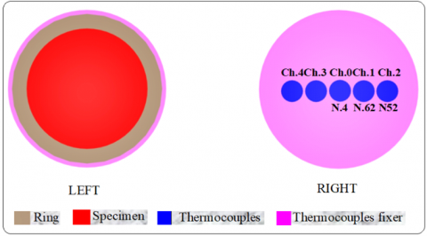
The excisional test technique by oxy-acetylene flame is described in Figure 2. The test specimens are 60mm in diameter and 1-10mm in thickness. Measurement specimens were held 19 mm from the tip of the torch. The test method was carried out using five K-type thermocouples which were mounted on the cold back face surface of the test specimen at five locations to measure temperature time continuously throughout the static test, (see Figure 5). Channels ch-0, ch-1, and ch-2 were chosen for our study for thermal analysis, which is equivalent to the temperature of nods for the analysis of the mathematical model, while channels ch-3 and ch-4 were excluded because of their location on the same axis and have the same thermal condition as channels ch-1 and ch-2. The thermocouples were connected to a digital computer with special software, a microprocessor thermometer manufactured by Comarc in order to directly measure surface temperature with time.
The thermal properties of the composite specimens were measured in the laboratory at room temperature. The thermal conductivity was measured by using Lee’s disc method. The Mercury displacement method was used to measure the density in this work, while, the specific heat capacity of the composite materials specimens under test was dependent on literature [33], and manufacturers' specifications. The detailed properties of the laminated test composites are listed in Table 5.
Figure 5. Location of K-type thermocouples on the composite test specimen
Table 5. Material properties of composites under test
|
Group |
Composite Code |
Thickness (mm) |
ρ (kg/m3) |
α (J/kg K) |
K (W/m K) |
|
A |
C1 |
6 |
1450 |
1250 |
0.55 |
|
C2 |
6 |
1450 |
1250 |
0.49 |
|
|
C3 |
6 |
1432 |
1250 |
0.40 |
|
|
C4 |
6 |
1430 |
1250 |
0.38 |
|
|
B |
C5 |
6 |
1448 |
1250 |
0.61 |
|
C6 |
6 |
1452 |
1250 |
0.60 |
|
|
C7 |
6 |
1458 |
1250 |
0.59 |
|
|
C8 |
6 |
1460 |
1250 |
0.553 |
3.4.2 Transient numerical thermal analysis
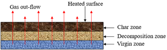
The basic problem is how to predict of thermal response for thermally decomposing specimens exposed to a defined thermal environment that may erode the thermal surface. The physical response of a charring thermal insulator is illustrated in Figure 6. As the composite specimens are heated, the pyrolysis gas yields from the virgin material, which percolates away from the pyrolysis zone. A porous residue, which for most materials is carbonaceous char, is then formed as described by:
$Virgin \,\,\, plastic \rightarrow char + gas$
In the virgin zone near the wall, the temperature is low and the decomposition reactions are not initiated. A conduction process is achieved in the decomposition zone, and a great part of the energy is observed by chemical reactions, which are in majority endothermic. In this zone, both conduction and mass transfer processes are achieved. In front of the combustion products, the rubber is fully decomposed and is in the state of carbon char. The present effort was devoted to the general conduction-ablation problem.
Figure 6. Zones formed due to the thermal response of the insulator
For the case study under analysis, the unsteady-state thermal analysis determines temperature distribution in one dimension as a function of time. The finite element method (FEM) is a powerful general technique for analyzing and obtaining an approximate solution to many engineering problems. Nowadays the method is generously applicable in large-scale programs, established to be in hand, very relevantly, due to the ever development in the computer hardware technology, which in sequence makes it possible to develop high-level software packages, compatible with personal computers, especially those which maintain inter-active manner with the user in easy and fast processing. Some of these available finite-elements packages are a series of ANSYS programs. The model describing this method is according to the following equation:
${{\rho }_{c}}\text{ }C{{p}_{\text{c}}}\frac{\partial T}{\partial t}=\frac{\partial }{\partial y}({{k}_{c}}\frac{\partial T}{\partial y})+({{h}_{g}}-{{h}_{c}})\frac{\partial \rho }{\partial t}+\frac{m_{g}^{\cdot }C{{p}_{g}}}{A}\frac{\partial T}{\partial y}$ (8)
In order to model the composite specimens, certain assumptions were proposed for mathematical simplicity;
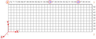
Figure 7 shows a configuration of the element in the lower right location of the single rigid axis symmetry plane based on ANSYS (PLAN 55 4 Nodes). The multilayered circular sample is modeled into finite elements (m × n), where m denotes the number of segmented columns parallel to the y-axis plate, and n the number of rows parallel to the x-axis. For the smart mesh size (finermesh 3), the nodal numbers, associated with one edge line, perform a numerical series depending on the magnitudes of m and n as well as the type of the used finite-element model (4-nodes type). This general layout of the nodal numbers helps effectively to construct a unified idealization for the boundary conditions to be employed for running of applied program.
The finite element models, chosen from the ANSYS library are the PLAN 55 (2-D, 4 nodes type). The base thermal analysis theory, upon which this package is established, is the transient thermal analysis as can be very well understood from the element-node distribution on a single plane (solid axisymmetry) within the composite domain.
Table 6 shows how the boundary conditions for the surface of the composite sample with a thickness from 6-10 mm, facing an oxy-acetylene flame, were chosen experimentally and theoretically.
Figure 7. The nodal numbering associated with the (2-D PLAN55 4-nodes /ANSYS ), FEM model type 10 mm
3.5 Discuss practical and theoretical results
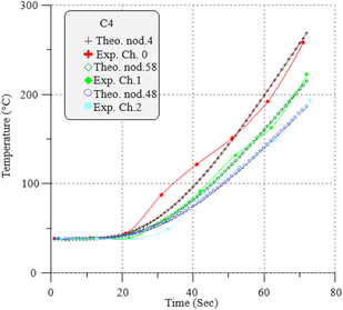
Based on the encouraging results obtained in Tables 4 and 5, Group A with Model C4 at a thickness of 10mm was selected to perform thermal analysis practically as specified in Figure 2 and theoretically by ANSYS programmed packages. These techniques are employed to investigate their capability levels for thermal analysis of solid axisymmetric composite discs.
In order to validate the results, a practical and theoretical comparison was made between them. Assuming that the initial conditions of the hot face facing the torch and the cold face are the same for all test specimens, moreover, the fiber volume fraction is also fixed. The only variable required to evaluate the thermal response of models is thickness. Referring to Table 7, experimental and theoretical results declare that there is a sensible contradiction in the period of time taken by the cold back face to reach 204℃. For group (A) composites, this period ranges from 42.6 to 63.4 seconds experimentally and from 43.5 to 61 seconds theoretically, the reasons for these differences arise from variations in thermal conductivity, the performance of composites towards insulation, percentage weight of reinforcement, matrix, erosion rate, insulation index and the nature of the structure of the charred layer facing the flame. The fiber reinforcement type (2DC) has many effects on the composite materials, which reflect the best erosion resistance, thermal conductivity, charring rate, and mechanical stresses.
The thermal stability of modified phenolic resin by Ni(acac)2·2NH3 plays an important role in the ablation and thermal conductivity results, these effects reflect the thermal behavior of the C4 composite through Figure 8.
Table 6. Experimental and theoretical boundary conditions
|
Sample Thickness (mm) |
Experimental Thot °C Depend on Figure 5 |
Theoretical Thot °C Depend on Figure 7 |
||||
|
1650 |
1200 |
1000 |
1650 |
1200 |
1000 |
|
|
6 |
Ch.0 |
Ch.1 |
Ch.2 |
N.1–17 |
N.18–28 |
N.29–2 |
|
7 |
Ch.0 |
Ch.1 |
Ch.2 |
N.1–16 |
N.17–27 |
N.28–2 |
|
8 |
Ch.0 |
Ch.1 |
Ch.2 |
N.1–15 |
N.16–26 |
N.27–2 |
|
9 |
Ch.0 |
Ch.1 |
Ch.2 |
N.1–14 |
N.15–25 |
N.26–2 |
|
10 |
Ch.0 |
Ch.1 |
Ch.2 |
N.1–13 |
N.14–24 |
N.25–2 |
Ch.0 (0-10 mm), Ch.1 (10-20 mm), Ch.2 (20-30 mm), N=Node
Table 7. Ablative parameters for carbon cloth-phenolic composites (group A) at 10 mm thickness.
|
No. |
Composite Code |
Time to Reach 204°C |
Insulation Index (sec/mm) |
Erosion Rate (mm /sec) |
|||
|
Experimental (ch-0) |
Theoretical (Nod-4) |
Experimental (ch-0) |
Theoretical (Nod-4) |
Experimental (ch-0) |
Theoretical (Nod-4) |
||
|
1 2 3 4 |
C1 C2 C3 C4 |
42.6 48.6 60.4 63.4 |
43.5 49.3 59.5 61 |
4.26 4.86 6.04 6.34 |
4.35 4.93 5.95 6.10 |
0.229 0.205 0.165 0.157 |
0.229 0.205 0.168 0.163 |
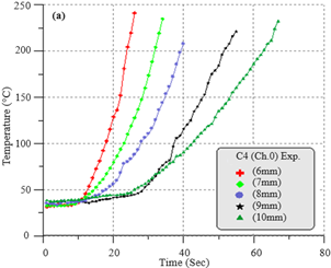
The predicted ablative parameters of 6, 7, 8, 9, and 10 mm thicknesses, 60 and 65% volume fraction of composite C4, during the flame test as plotted in Figure 9. The temperature response depends only on the physical properties of the composite specimens and their thickness. Because the temperature is high on the hot side of the specimens facing the flame, decomposition of the endothermic resin occurs with time, and as a result, the resin material facing the flame is sacrificed at a high speed.
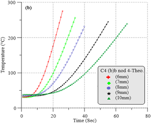
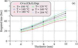
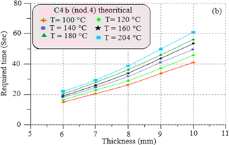
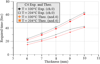
The experimental and theoretical required times as a function of thickness at various temperatures for composite C4 are plotted in Figures 10 and 11. The values are also listed in Table 8. From this set of data, it may be concluded that the required time for the composite to reach 204°C increases with increasing thickness because the rate at which heat is transferred by conduction is proportional to the temperature gradient dT/dx. Moreover, the actual rate of heat flow depends also on the thermal conductivity, as the composite C4 showed a low thermal conductivity which required a longer period to reach 204℃.
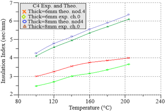
The experimental and theoretical linear relationships between insulation index and temperature at different thicknesses of 6-10 mm are plotted in Figures 12 and 13.
Figure 8. Experimental and theoretical surface temperature histories of composite C4 at 10 mm thickness
Figure 9. Surface temperature histories of composite H36 at various thicknesses, (a) experimental; (b) theoretical
Figure 10. Design chart prepared using the thermal response mode of composite C4 vs. thickness, (a) experimental; (b) theoretical
Figure 11. A comparison of the experimental and theoretical required time vs. thickness based on the thermal response mode of composite C4
It showed that the composite C4 with a thickness of 10 mm is the best insulation index to reach 204℃, and therefore it gives the longest burning period over time and higher corrosion resistance, and this is consistent with the results that indicate the lower the thermal conductivity, the higher the insulation index.
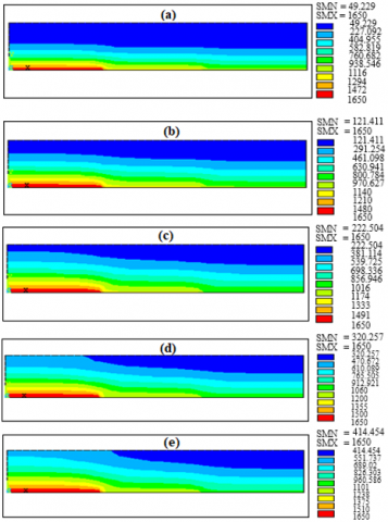
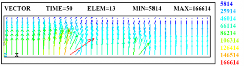
Thermal response and temperature distribution of the specimens as a function of time are verified by Figure 14, which shows a two-dimensional (2D) color contour plot of the temperature distribution of the C4 compound after exposure to an oxyacetylene flame for 10, 20, 30, 40, and 50 seconds. A noticeable temperature change is observed in the areas corresponding to (ch-0 and Nod-4), which are exposed to 1650℃. Figure 15 shows the heat vector pattern of the three regions as illustrated in Table 6. Heat transfer starts from the hot end of the sample at a temperature of around 1600℃ up to the cold end, while some of the other heat vector patterns divert toward other parts of the sample of lower temperature.
Table 8. Ablative parameters for carbon cloth-phenolic composites (group A) at 10 mm thickness
|
No. |
Thickness (mm) |
Time to Reach 204℃ |
Insulation Index (sec/mm) |
Erosion Rate (mm /sec) |
|||
|
Experimental (ch-0) |
Theoretical (Nod-4) |
Experimental (ch-0) |
Theoretical (Nod-4) |
Experimental (ch-0) |
Theoretical (Nod-4) |
||
|
1 2 3 4 5 |
6 7 8 9 10 |
24 32 41.5 52.5 63.4 |
22 29.5 38.9 49.8 61 |
4.00 4.57 5.18 5.83 6.34 |
3.66 4.21 4.86 5.53 6.10 |
0.250 0.218 0.193 0.171 0.157 |
0.273 0.237 0.205 0.180 0.163 |
Figure 12. Insulation index vs. back face temperature of composite C4 at various thicknesses, (a) experimental; (b) theoretical
Figure 13. A comparison of the experimental and theoretical insulation index vs. back face temperature of composite C4 at various thicknesses
Figure 14. Ansys’s contour plot of the temperature distribution for a 6 mm thickness of composite C4 after time exposure to oxy-acetylene flame, (a) 10 sec; (b) 20 sec; (c) 30 sec; (d) 40 sec; (e) 50 sec
Figure 15. Ansys’s heat vector at time (50 sec) for 6 mm thickness of composite C4
The X-ray results indicated that samples containing concentrations of 3, 5, and 10 wt% Ni(acac)2.2NH3 show the most graphical structure consistent with the T and G component, due to the presence of NixC crystals.
The charred carbons containing 10 wt% Ni(acac)2.2NH3 within the chemical structure of novalac exhibited higher graphitization levels than 3 and 5 wt%, with a d002 of 3.35 Å, with Lc of 241 Å and graphitization level of 37.5%.
The presence of ammonia molecules coordinated to nickel ion in Ni(CH2COCH2COCH3)2.2NH3 allows for hydrogen bonding with the polymer units as was indicated by the broadening of bands related to N-H stretching vibration, the shift of polymer OH stretching vibration to lower frequencies and the reduction of intensity of dNH vibration.
C4 and C8 composites, which have the highest percentage of nickel complex, have the lowest corrosion rate, and the highest isolation index. This is due to the fact that the chemical interaction between the organic metal compounds and Novalac has improved the thermal properties of the charring layer to resist erosion and act as a mechanical stabilizer to this layer, also which makes its decomposition slower than the traditional resin, and also since the nickel carbide particles diffuse into the inner part of the carbon particles, leaving the G and T components behind, thus preventing the carbon material from oxidizing and then reducing the rate of decomposition of resin in composites at elevated temperature during heat treatment under an oxy-acetylene flame.
G and T structures have a notable role in improving the thermal properties of the charring carbon to resist erosion caused by gas flow stresses.
The erosion rate of plain-woven phenolic composites (2DC) is much lower than that of chopped fiber composites (CHC) because have excellent shear resistance and low density.
From the experimental and theoretical results, it may be concluded, that the required time for composites to reach 204℃ increases with increasing thickness and insulation index. On the other hand, the C4 composite is the best thermal conductor. Hence, it gives the longest burn through time indicating a lower erosion rate, because the rate of heat transfer by conduction is proportional to the temperature gradient dT/dx. Furthermore on thermal conductivity, compound C4 showed low thermal conductivity which required a longer period to reach 204℃.
The accuracy between the theoretical and practical results ranged from 87-92%, and the results can be used as a guide for thermal insulator designers to choose the appropriate thickness and reduce effort and costs in processing practical applications.
It can be distinguishing current work through taking advantage of the results of thermal analysis of composites to build an information base that insulation engineers can rely on in choosing the ideal insulator to reduce effort and costs in order to address practical applications.
A typical suggestion for possible further work is to search for more mineral complexes and inorganic compounds that can accelerate the graphitization process and increase the thermal stability of the polymer toward thermal ablation. We believe that more work is needed to measure thermal properties as a function of temperature up to 2000℃.
Thanks and appreciation go to the Department of Chemical Engineering/University of Technology, Al-Quds General Company, Al-Milad General Company, the University of Baghdad/Department of Science, and the Geological Survey Department for their support and assistance in making this work a success.
|
NV0 |
Non modified novolac resin |
|
NVm |
Modified novolac resin |
|
Gl |
graphitization level, % |
|
Agr .C |
graphitic carbon area, mm-2 |
|
Atotal |
graphitic + non graphitic carbon area, mm-2 |
|
b |
burn- through time, s |
|
CR |
char rate, mm. s-1 |
|
CR,avg |
average char rate, mm. s-1 |
|
d |
original thickness of specimen, mm |
|
Er |
erosion rate, mm. s-1 |
|
Er, avarage |
average erosion rate, mm. s-1 |
|
I |
insulation index at temperature T, s. mm-1 |
|
N |
number of replicates |
|
tT |
time for back–face temperature at 204°C, s |
|
Iavg |
average insulation index at T, s. mm-1 |
|
FEM |
Finite element method |
|
Greek symbols |
|
|
$\alpha$ |
thermal diffusivity, m2. s-1 |
|
$\rho$ |
density, Kg. m-3 |
|
k |
Thermal conductivity, W.m-1. k-1 |
[1] Kazuhisa, H., Masakatsu, A. (2013). Phenolic resins-100 years of progress and their future. Reactive and Functional Polymers, 73(2): 256-269. https://doi.org/10.1016/j.reactfunctpolym.2012.07.003
[2] Winya, N., Boonpan, A., Prapunkarn, K. (2013). Study of factors affecting the ablation rate of phenolic resin/fiber glass. International Journal of Chemical Engineering and Applications, 4(4): 234.
[3] Pulci, G., Tirillò, J., Marra, F., Fossati, F., Bartuli, C., Valente, T. (2010). Carbon-phenolic ablative materials for re-entry space vehicles: manufacturing and properties. Composites Part A: Applied Science and Manufacturing, 41(10): 1483-1490. https://doi.org/10.1016/j.compositesa.2010.06.010
[4] Soutis, C. (2005). Carbon fiber reinforced plastics in aircraft construction. Materials Science and Engineering, 412(1-2):171-176. https://doi.org/10.1016/j.msea.2005.08.064
[5] Binner, J., Hogg, P., Murphy, J. (eds) (2013). Advanced Materials Source Book. Elsevier.
[6] Shen, H., Lavoie, A.J., Nutt, S.R. (2003). Enhanced peel resistance of fiber reinforced phenolic foams. Composites Part A: Applied Science and Manufacturing, 34(10): 941-948. https://doi.org/10.1016/S1359-835X(03)00210-0
[7] Wang, Y., Chen, L., Xu, T., Yan, Y., Gu, J., Yun, J., Feng, J. (2017). High char yield novolac modified by Si-B-N-C precursor: Thermal stability and structural evolution. Polymer Degradation and Stability, 137: 184-196. https://doi.org/10.1016/j.polymdegradstab.2017.01.013
[8] Farhan, S., Li, K.Z., Guo, L.J., Gao, Q.M., Lan, F.T. (2010). Effect of density and fibre orientation on the ablation behaviour of carbon-carbon composites. New Carbon Materials, 25(3): 161-167. https://doi.org/10.1016/S1872-5805(09)60023-8
[9] Bacos, M.P., Dorvaux, J.M., Lavigne, O., Talandier, J. (2000). C/C composite oxidation model: III. Physical basis, limitations and applications. Carbon, 38(1): 105-117. https://doi.org/10.1016/S0008-6223(99)00105-0
[10] Levet, C., Helber, B., Couzi, J., Mathiaud, J., Gouriet, J. B., Chazot, O., Vignoles, G.L. (2017). Microstructure and gas-surface interaction studies of a 3D carbon/carbon composite in atmospheric entry plasma. Carbon, 114: 84-97. https://doi.org/10.1016/j.carbon.2016.11.054
[11] Aubard, X., Cluzel, C., Guitard, L., Ladeveze, P. (2000). Damage modelling of a 4D carbon/carbon composite for high temperature application. Ceramics International 26(6): 631-637. https://doi.org/10.1016/S0272-8842(99)00108-X
[12] Hong, C., Han, J., Zhang, X., David, H., Li, W., Chen, Y., Du, S. (2012). Novel phenolic impregnated 3-D Fine-woven pierced carbon fabric composites: Microstructure and ablation behavior. Composites Part B: Engineering, 43(5): 2389-2394. https://doi.org/10.1016/j.compositesb.2011.12.001
[13] Liu, Y, Liu, L., Deng, J., Meng, R., Zou, X., Wu, F. (2017). Fabrication of micro-scale textured grooves on green ZrO2 ceramics by pulsed laser ablation. Ceramics International, 43(8): 6519-6531. https://doi.org/10.1016/j.ceramint.2017.02.074
[14] Zou, C., Zhang, C., Li, B.,Wang, S., Xie, Z., Song, Y. (2015). Ablation behavior of boron nitride based ceramic composites reinforced by continuous silicon oxynitride fiber. Ceramics International, 41(3): 4768-4774. https://doi.org/10.1016/j.ceramint.2014.12.027
[15] Ma, C., Ma, Z., Geo, L., Liu, Y., Wu, T., Wang, F., Ishida, H. (2019). Ablation behavior of boron-modified phenolic resin irradiated by high-energy continuous-wave laser and its evolution of carbon structure. Materials & Design, 180(15): 107954. https://doi.org/10.1016/j.matdes.2019.107954
[16] Farhan, S., Wang, R.M., Li, K., Wang, C. ( 2015). Sublimation and oxidation zone ablation behavior of carbon/carbon composites. Ceramics International, 41(10):13751-13758. https://doi.org/10.1016/j.ceramint.2015.08.043
[17] Lachaud, J., Bertrand, N., Vignoles, G.L., Bourget, G., Rebillat, F. Weisbecker, P. (2007). A theoretical/experimental approach to the intrinsic oxidation reactivities of C/C composites and of their components. Carbon, 45(14): 2768-2776. https://doi.org/10.1016/j.carbon.2007.09.034
[18] Yin, J., Xiong, X., Zhang, H., Huang, B. (2006). Microstructure and ablation performances of dual-matrix carbon/carbon composites. Carbon, 44(9): 1690-1694. https://doi.org/10.1016/j.carbon.2006.01.017
[19] Shimada, S. (2002). A thermoanalytical study on the oxidation of ZrC and HfC powders with formation of carbon. Solid State Ionics, 149(3-4): 319-326. https://doi.org/10.1016/S0167-2738(02)00180-7
[20] Chang, Y., Sun, W., Xiong, X., Chen, Z., Wang, Y., Hao, Z., Xu, Y. (2016). Microstructure and ablation behaviors of a novel gradient C/C-ZrC-SiC composite fabricated by an improved reactive melt infiltration. Ceramics International, 42(15): 16906-16915. https://doi.org/10.1016/j.ceramint.2016.07.190
[21] Dong, Z.J., Liu, S.X., Li, X.K., Westwood, A., Yuan, G. M., Cui, Z.W., Cong, Y. (2015). Influence of infiltration temperature on the microstructure and oxidation behavior of SiC–ZrC ceramic coating on C/C composites prepared by reactive melt infiltration. Ceramics International, 41(1): 797-811. https://doi.org/10.1016/j.ceramint.2014.08.138
[22] Wang, W., Jin, X., Huang, H., Hu, S.,Wu, C., Wang, H., Pan, Y., Hong, C., Zhang, X. (2023). Thermal-insulation and ablation-resistance of Ti-Si binary modified carbon/phenolic nanocomposites for high-temperature thermal protection. Composites Part A: Applied Science and Manufacturing, 169: 107528. https://doi.org/10.1016/j.compositesa.2023.107528
[23] Xin, Y., Niu, Z., Shen, S., Ma, X., Chen, F., Wang, L., Chen, B., Wang, C., Zhang, C., Hou, X. (2023). A novel B–Si–Zr hybridized ceramizable phenolic resin and the thermal insulation properties of its fiber-reinforced composites. Ceramics International, 38(3,1): 4919-4928. https://doi.org/10.1016/j.ceramint.2022.10.006
[24] Huang, Y., Liu, Z., Yan, L., Zou, H., Chen, Y., Liang, M. (2023) Enhanced ablation resistance of phenolic composites through the construction of a sea-island nanostructured char layer via in-situ catalytic graphitization of incorporated Salen-Ni complex. Chemical Engineering Journal, 464(15): 142651. https://doi.org/10.1016/j.cej.2023.142651
[25] Niu, Z., Chen, B., Shen, S., Zhang, H., Ma, X., Chen, F., Li, L., Xin, Y., Zhang, C., Hou, X. (2022). Zirconium chelated hybrid phenolic resin with enhanced thermal and ablation resistance properties for thermal insulation composites. Composites Communications, 35: 101284. https://doi.org/10.1016/j.coco.2022.101284
[26] Zhang, C., Lu, G., Sun, Z., Yu, J. (2012). Catalytic graphitization of carbon/carbon composites by lanthanum oxide. Journal of Rare Earths, 30(2): 128-132. https://doi.org/10.1016/S1002-0721(12)60008-8
[27] Al-Falahi, H. (2014). Catalytic graphitization of modified phenolic resin and its nanoparticles fillers behavior towards high temperature. Journal of Advanced Materials Research, 925: 282-289. https://doi.org/10.4028/www.scientific.net/AMR.925.282
[28] Al-Falahi, H.A. (2022). Study the effect of chromium complex on the graphitization of phenolic resins for developing thermally stable nano carbon fillers. In AIP Conference Proceedings, 2443(1). AIP Publishing. https://doi.org/10.1063/5.0093813
[29] Talabi, S.I., Luz, A.P.D., Pandolfelli, V.C., Lima, V.H., Botaro, V.R., Lucas, A.D.A. (2020). Graphitization of lignin-phenol-formaldehyde resins. Materials Research, 23. https://doi.org/10.1590/1980-5373-MR-2019-0686
[30] Lum, R., Wilkins, C.W., Robbins, M., Lyons, A.M., Jones, R.P. (1983). Thermal analysis of graphite and carbon-phenolic composites by pyrolysis-mass spectrometry. Carbon, 21(2): 111-116. https://doi.org/10.1016/0008-6223(83)90165-3
[31] Xu, B., He, R., Hong, C., Ma, Y., Wen, W., Li, H., Cheng, T., Fang, D., Yang, Y. (2017). Ablation behavior and mechanism of double-layer ZrB2-based ceramic coating for lightweight carbon-bonded carbon fiber composites under oxyacetylene flame at elevate temperature. Journal of Alloys and Compounds, 702(25): 551-560. https://doi.org/10.1016/j.jallcom.2017.01.242
[32] Ma, L., He, L.J., Mo, C.S., Zhang, L.B., Pan, M.S., Huang, Y.F.F. (2017). Ablation behaviour and microstructure of carbon/carbon and hybrid carbon/carbon composites based on plasma torch heating. Advanced Composites Letters, 26(4). https://doi.org/10.1177/096369351702600401
[33] Goetzel, C.G. (1980). High-temperature properties of some reinforced phenolic composites. http://pascal-francis.inist.fr/vibad/index.php?action=getRecordDetail&idt=PASCAL8130107881.
[34] Henderson, J.B., Tant, M.R., Doherty, M.P., O'Brien, E.F. (1987). Characterization of the high-temperature behaviour of a glass-filled polymer composite. Composites, 18(3): 205-215. https://doi.org/10.1016/0010-4361(87)90410-1
[35] Bitencourt, C.S., Luz, A.P., Pagliosa, C., Pandolfelli, V.C. (2015). Role of catalytic agents and processing parameters in the graphitization process of a carbon-based refractory binder. Ceramics International, 41(10): 13320-13330. https://doi.org/10.1016/j.ceramint.2015.07.115