Enoch M. Adediran | David A. Fadare![]() | Ayodeji Falana | Rasaq A. Kazeem
| Ayodeji Falana | Rasaq A. Kazeem![]() | Omolayo M. Ikumapayi*
| Omolayo M. Ikumapayi*![]() | Adebayo S. Adedayo
| Adebayo S. Adedayo![]() | Adedotun O. Adetunla
| Adedotun O. Adetunla![]() | Umeh J. Ifebunandu | Dorcas A. Fadare
| Umeh J. Ifebunandu | Dorcas A. Fadare![]() | Elisabeta S. Olarinde
| Elisabeta S. Olarinde![]()
© 2023 IIETA. This article is published by IIETA and is licensed under the CC BY 4.0 license (http://creativecommons.org/licenses/by/4.0/).
OPEN ACCESS
The study presents the development of an accessible, reliable, 3D printable, low-cost, and modular 4 degrees-of-freedom robotic arm for the automated sorting of plastic bottles from the waste stream. The UIArm I robot arm was designed based on the modification of an open-source Thor Robot model using Free-CAD with the components 3D printed using PLA and PETG. The forward kinematics was obtained by Denavit-Hartenberg (DH) method, while the analytical method was used for the inverse kinematics. The electrical components include stepper motors, servo motors, motor drivers, a printed circuit board (PCB), an Arduino Mega microprocessor, a light source for illumination, and a PC with a webcam. Python was used for programming the PC and C# for the Arduino microprocessor. TensorFlow, an end-to-end open-source, machine learning platform was used to develop the object detection algorithm based on a deep neural network. The object detection model achieved an accuracy of 91% for Pepsi plastic bottles which formed the bulk of training images. Other types of plastic bottles were detected with an 85% accuracy. The study has demonstrated the viability of a locally developed robotic arm for the automated sorting of plastic bottles.
machine vision, complex backgrounds, deep learning, robotic grasping, garbage sorting
1.1 Machine vision, complex backgrounds, deep learning, robotic grasping, garbage sorting
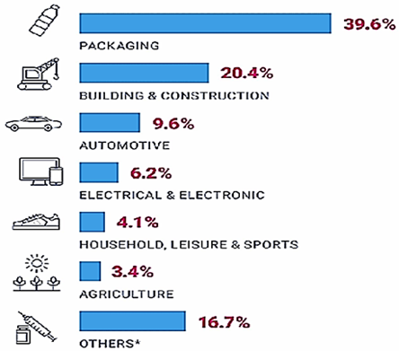
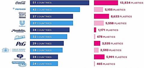
Over the years, solid waste management has remained a major challenge faced by developing countries. Increased population, urbanization, and improved standard of living are the leading contributory factors to the astronomic increase in a solid waste generation but without corresponding technological innovations in the management of these wastes. Global production of plastics has increased twentyfold since the 1960s, reaching 322 million tonnes in 2015. It is expected to double again over the next 20 years to reach over 600 million tonnes by the year 2025 [1]. More than half (56%) of plastic ever produced has been made since 2020. About 40% of the global plastic production is used for packaging followed by the construction and automotive industries as shown in Figure 1 [2]. In the packaging industry, the beverage industry (soft drink manufacturers) is responsible for the larger share of plastic usage. International research in 2020 shows that Coca-Cola products contributed the highest plastic bottles found in the environment in over fifty-one countries followed by Pepsi and Nestle products as shown in Figure 2 [2]. Worldwide, plastic bottles constitute over 50% of the volume of waste generation in both developed and developing nations. Every second, about 15,000 plastic bottles are sold worldwide, corresponding to about 1 million per minute and 480 billion in a year [2]. Coca-Cola produces 167,000 plastic bottles every minute [3]. However, only 7% of these plastic bottles are recycled, even though the material used (PET) is one of the easiest to recycle. More than half (about 5 billion tonnes) of the 9.2 billion tons of plastic bottles that have been produced to date has ended up as waste in landfill or has simply ended up in the environment [2]. Of this number, between 5 and 13 million tonnes of plastic bottles enter the oceans. With global plastic production estimated to increase by 40% in the next 10 years, if there are no decisive technological interventions regarding plastic bottle management, the oceans are predicted to carry more plastic bottles than fish (by weight) by 2050 [2]. The United Nations, however, has warned that marine life will be irreparably destroyed as the coral reefs appear to be particularly vulnerable to plastic pollution while the food supply chain of millions of people will be endangered [4].
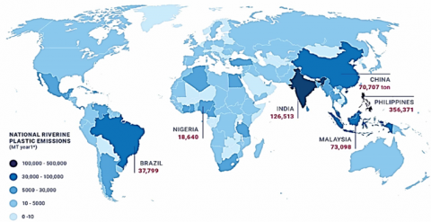
In Plastic Soup [4], it has been reported that the total plastic bottles emitted into the ocean stand at 18,640 metric tonnes per year in Nigeria (Figure 3). This is due largely to the fact that there is no mechanized sorting technology aside from manual sorting for the segregation of the plastic bottles from the waste stream as waste sorting from the source is uncommon in Nigeria as in developed countries. Manual sorting is known to be labour-intensive, time-consuming, and cost ineffective as well as injurious to the health of sorters. Hence, there is little, or no recycling of plastic bottles practiced in Nigeria. Therefore, to overcome these challenges, there is a need to develop a mechanized sorting system using the robotic arm. This study therefore presents the development of an accessible, reliable, 3D printable, low-cost, and modular 4 degrees-of-freedom robotic arm for the automated sorting of plastic bottles from the waste stream.
Figure 1. Global plastic usage by sector [4]
Figure 2. The number of countries in which plastic bottles are found and the quantity recorded [4]
Figure 3. Total emitted plastic into the ocean metric tonnes per year per country [4]
1.2 Applications of the robotic arm in waste management
A robotic arm is a mechanical arm designed to perform programmable tasks similar to those performed by human arms. Various configurations of robot arms have been built over the past several decades. Conventionally, each joint on the robot arm is moved by actuators that displace it linearly or at an angle. The actuators could be electric, pneumatic, or hydraulic depending on the type and conditions of work. Electric actuators like servos and stepper motors are the most common due to their low cost and simplistic design.
Prospects of robot applications in recycling and product disassembly have been reported by Bogue [5]. The global waste sorting robots market has been reported by Goldstein [6]. In Bangladesh, an intelligent system using a robotic arm was developed for automatically sorting the waste using 11 objects (waste) of different sizes and types. The experimental results showed that the proposed system was reliable and achieved about 82% accuracy for the categorization of different types of waste [7]. Noshahi [8] also presented a low-cost locally manufactured 4 degree of freedom (DOF) pick and place robotic arm that can be used for industrial assembly line applications such as textile, automobile, and agriculture sectors for waste sorting. The design and fabrication of a new soft robot hand for grasping and sorting operations was proposed by Wang and Guo [9]. The robot hand was driven by five pneumatic actuators. A prototype of the robot hand was fabricated (Universal Robot UR5) and used to grasp any shaped object in a certain space by providing high safety and high adaptability. Recently, a robust system for the automation of municipal waste sorting using a robot arm with artificial intelligence was developed by Wilts et al. [10]. Chang et al. [11] designed an intelligent mobile garbage collection robot based on visual recognition technology, which can carry out path planning, traverse the given area, scan and identify and pick up recyclable garbage. The proposed system consisted of a navigation unit, target identification unit, and sorting control unit. None of these research works were particularly targeted at sorting plastic bottles from the waste stream. The purpose of the study is to develop an affordable, reliable, 3D printable, low-cost, and modular 4-degree-of-freedom robotic arm for automated sorting of plastic bottles and therefore providing the platform for pushing the limits of robotics studies and alleviating the menace of plastic pollution in Nigeria. The Automation and Robotic laboratory of the Faculty of Technology, University of Ibadan are set to spearhead this innovation. The UIArm I is our pioneering effort with great potential that can be scale-up, modified, and trained to accomplish complex tasks. In the nearest future, we look forward to having more robust robotic hands with great capabilities.
2.1 Mechanical design
The mechanical components were designed based on the modification of an open-source, six-degree-of-freedom Thor Robot, which was released in 2017 [12]. Since then, the model has undergone many modifications, adaptations, and applications by numerous researchers worldwide and more than 20 units have been built in at least 11 different countries [13-19]. FreeCAD, an open-source 3D modeling software was used to model the robotic arm. Thor robotic arm model was modified by scaling down the number of links and degree of freedom for simplicity and cost reduction but maintaining the functionality of the robotic arm. The developed model has a 4 degree of freedom with a 2-fingered gripper for grasping.
2.1.1 Design of Joint 1
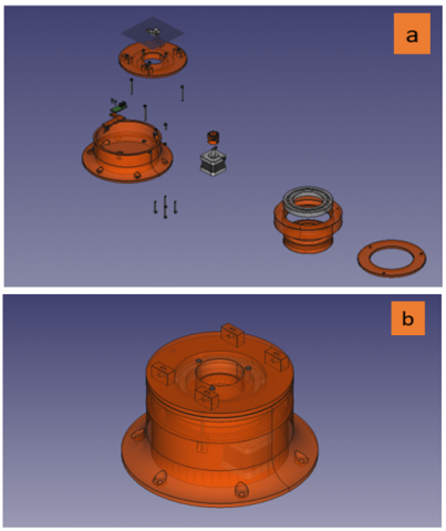
The joint consists of the base of the arm, with a revolute joint that moves the entire robot 360° rotationally on the z-axis. It is powered by a Nema 17 stepper motor with holding torque of 39.22N.cm. The motor has a shaft length of 40mm with a rated current of 1.5A. The stepper motor drives an internal helical gear that sits within the base frame. The top of the base frame sits on a 55mm diameter 16014ZZ ball bearing for frictionless rotation. The 3D model of joint 1 is shown in Figure 4.
Figure 4. 3D model of joint 1 (a) exploded view (b) assembled view
2.1.2 Design of Joint 2
The second joint is revolute with 120° rotations about the y-axis of the reference frame, powered by 2 stepper motors. The stepper motors are fitted with 2 helical gears which mesh with the inner teeth of the shoulder carrying the second link of the robotic arm with a 5:1 gear reduction ratio with 121.2N.cm of holding torque. The 3D model of joint 2 is shown in Figure 5.
Figure 5. 3D model of joint 2
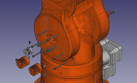
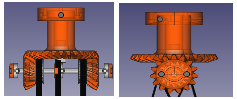
2.1.3 Design of Joints 3 and 4
Joints 3 and 4 are also revolute joints with 180° rotation about the y-axis and 360° rotations about the z-axis respectively. To reduce the weight and inertia of the links, the 2 stepper motors powering the links are located in the lower link. The joints are driven with GT20 belts via 2 pulleys of a semi-differential gear system. The 3D models of the joints are depicted in Figure 6.
Figure 6. 3D models of joints 3 and 4
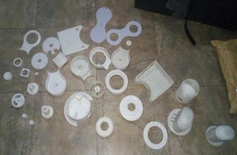
2.2 3D printing
The Free CAD models were sliced using the Ultimaker Cura slicer, open-source software, and the .stl files were printed on a commercial 3D printer in Ibadan, Nigeria. PLA was used for smaller components while PETG was used for the larger components. A total of 43 parts were printed. Figure 7 shows the image of some of the 3D printed components.
Figure 7. 3D printed components
2.3 Electrical design
The electronic components include 5 stepper motors with A4988 motor drivers, 1 servo motor and driver, limit and power switches, and cooling fans mounted on a printed circuit board (PCB) produced by Thor Robot. The PCD has 36 input pins that are interfaced with an Arduino Mega microcontroller. The PC used was an ACER Aspire running on Windows 10 with Intel CORE i7, 8th generation quad-core processor with Nvidia Graphics Card MX150. A Webcam with resolutions up to 800 by 600 with a frame capturing rate of 30fps was used for the image acquisition. For consistent illumination and background, an incandescent bulb was used as a light source and brown cardboard paper was used for the background for the image acquisition.
2.3.1 Object detection model
The object detection model was built using TensorFlow API version 1.14.0, an open source, end-to-end platform for the implementation and deployment of large-scale machine learning models developed by Google [20]. The API was executed on Python v3.7which was later compiled to C++. To take advantage of the GPU, CUDA v10.0 and cuDNN v9.0 which are compatible with the version of TensorFlow were installed. To compile and build the necessary C++ encoders, Microsoft Visual Studio 2017 was installed and the C++ Build tools v2017 were installed [21]. To generate a robust training dataset for the machine learning algorithm, over 200 images of a typical waste stream containing plastic bottles with random poses or orientations under a variety of backgrounds and lighting conditions were taken using a smartphone. The desired objects (plastic bottles) in the images were identified manually and annotated using the LabelImg tool [22]. All bounding boxes for the plastic bottles in each image were individually drawn and exported as an XML. The TFRecords were generated, labels were mapped, and the training was configured to use the Faster-RCNN-Inception-V2 model for transfer learning. The image dataset was partitioned randomly into three sets with 70% used for training, 20% for validation, and 10% used for testing the model. Running the training process on the PC was not feasible due to system specifications limitations. Hence, the training and other heavy computations were done on Google Cloud’s COLAB running on a virtual machine. The training was allowed to run for 9 hours with 200 steps and the inference graph was exported for use on a local PC. The pose of the object detection was determined using the minimum area method. In this case, the image was rotated 90 times at one-degree intervals. The boundary box areas were calculated for each rotation and the minimum boundary box area was used approximately as the area of the object. The coordinate (x, y, z) of the object was determined by the centroid of the area, while the pose or orientation was determined by the angle of rotation. The current position of the robotic arm is then compared to the location of the detected object and serial information for the control system is fed into the Arduino Mega to control the required motor of the arm of the robot. The stepper motors are controlled with the Arduino Mega by sending HIGH and LOW pulses. The robotic arm was then moved to this coordinate based on the inverse kinematics and the gripper was then rotated based on the calculated pose angle in the opposite direction. The order and delay of these pulses determine the direction and speed of rotation of the motor. The Arduino code was written on the Arduino IDE in C#. The Python script sends information using the PySerial library. The script sends single character digits which the Arduino converts into pulses.
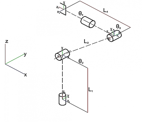
2.4 Kinematics analysis
2.4.1 Forward kinematics
The Denavit-Hartenberg (DH) method was used to analyze the forward kinematics of the robot. The Kinetic structure, and the schematics of the robotic arm are shown in Figure 8 and 9, respectively. By assigning coordinate frames to the links of the robot, its motion can be analyzed by obtaining a transformation that relates the joint space to the task space. Using transformation matrices $A_i \in R^{4 \times 4}$, the relative position and orientation of two link coordinate frames are obtained as shown below:
$T_n^o=\prod_{i=1}^n A_i$ (1)
where,
$A_i=\left[\begin{array}{cccc}c \theta_i & -s \theta_i c \alpha_i & s \theta_i s \alpha_i & a_i c \theta_i \\ s \theta_i & c \theta_i c \alpha_i & -c \theta_i s \alpha_i & a_i s \theta_i \\ 0 & s \alpha_i & c \alpha_i & d_i \\ 0 & 0 & 0 & 1\end{array}\right], \quad i=1, n$ (2)
Moreover, cθi and sθi are cos(θi) and sin(θi), and ai, αi, di, and θi are the link length, twist, distance, and joint variables respectively.
Figure 8. Kinematic structure
Figure 9. Schematics of the robotic arm
Using the Denavit-Hartenberg (DH) convention, the joint parameters are shown in Table 1.
Table 1. D-H parameters of the proposed robotic arm
|
Joints |
αi-1(rad) |
ai-1(mm) |
θi-1(rad) |
di-1(mm) |
|
1 |
π/2 |
0 |
0 |
0 |
|
2 |
0 |
L2 |
θ2 |
0 |
|
3 |
-π/2 |
0 |
θ3 |
0 |
|
4 |
0 |
L4 |
θ4 |
0 |
The transformation matrix:
$T^0{ }_4=A^0{ }_1 A^1{ }_2 A^2{ }_3 A^3{ }_4$ (3)
2.4.2 Inverse kinematics
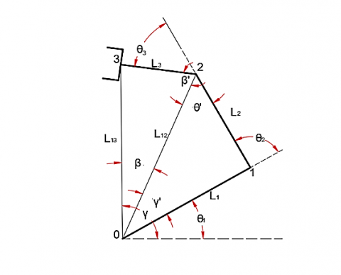
The inverse kinematics of this robot was done analytically, taking advantage of the geometric configuration of the robot: Given below are links 1, 2, and 3 and the distance (L13) between the end-effector frame 3 and frame 0: L1=30mm; L2=15mm, L3=20mm:
$L_{13}=\sqrt{x_3{ }^2+y_3{ }^2}$ (4)
To simplify our analysis, we make L12=αL13.
Taking L12=αL13, (α=1.2) we proceed thus:
Recalling the law of cosines and sines respectively,
$a^2=b^2+c^2-2 a b \cos C, \frac{\sin A}{a}=\frac{\sin B}{b}$
where, a, b and c are the lengths of the three sides of a triangle and A, B and C are the interior angles of the triangle opposite the sides of lengths a, b, and c respectively. Referring to Figure 1, just as angles θ2 and θ3, angle θ2 restricted to lie in the interval [0, π], can be determined from the law of cosines:
$L_{12}^2=L_1^2+L_2^2-2 L_1 L_2 \cos \theta_2$ (5)
Which follows that:
$\theta_2=\arccos \left(\frac{L_{12}^2-\left(L_1^2+L_2^2\right)}{2 L_1 L_2}\right)$ (6)
Also, from the law of sines,
$L_{12} \sin \theta^{\prime}=L_1 \sin \theta_2$ (7)
Which follows that:
$\theta^{\prime}=\arcsin \left(\frac{L_1 \sin \theta_2}{L_2}\right) \in[0, \pi]$ (8)
In addition, from the law of cosines, we have that:
$L_3^2=L_{{ }_{13}}^2+L_{12}^2-2 L_{13} L_{12} \cos \beta$ (9)
Hence,
$\beta=\arccos \left(\frac{L_{13}^2+L_{12}^2-L_3^2}{2 L_{13} L_{12}}\right) \in[0, \pi]$ (10)
Furthermore, from the law of sines, we obtain:
$L_{13} \sin \beta=L_2 \sin \beta^{\prime}$ (11)
These yields
$\beta^{\prime}=\arcsin \left(\frac{L_{13} \sin \beta}{L_3}\right)$ (12)
Since $\pi=\beta^{\prime}+\theta^{\prime}+\theta_3$, then
$\theta_3=\pi-\left(\beta^{\prime}+\theta^{\prime}\right) \in[0, \pi]$ (13)
Using the sine rule, we have that:
$L_{12} \sin \gamma^{\prime}=L_2 \sin \theta_2$ (14)
So,
$\gamma^{\prime}=\arcsin \left(\frac{L_2 \sin \theta_2}{L_{12}}\right)$ (15)
Noting that
$\gamma=\arctan \left(y_3 / x_3\right)$ (16)
And that
$\gamma=\beta+\gamma^{\prime}+\theta_1$ (17)
Then
$\theta_1=\gamma-\left(\beta+\gamma^{\prime}\right) \in[0, \pi]$ (18)
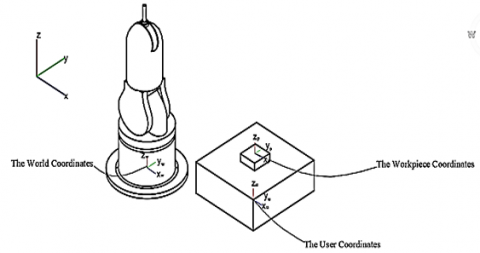
2.4.3 Robot coordinate system
The robot coordinate system used is a Cartesian coordinate system, which has its origin in the footprint of a robot (see Figure 10). It describes the position of the robot regarding the world coordinate system. For simple transformation, we set the origin of the robot coordinate system with the origin of the world coordinate system. The user coordinate system defines the coordinates of the acquired image, while the workpiece coordinate system defines the coordinate of the object identified in the image. The coordinate of the object in the image was transformed into the world coordinate system.
Figure 10. Robot coordinate system
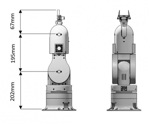
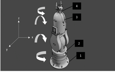
The designed model is about 464 mm high with a payload capacity of 500 g. The configuration of the model is shown in Figure 11. The model is configured on its four joints to yaw-roll-roll-yaw [23]. The joint configuration and parameters are shown in Figure 12 and Table 2, respectively. The experimental setup of the system is shown in Figure 13.
Figure 11. 3D model of the proposed UIArm I Robot Arm
Figure 12. The joint configuration of the UIArm I robotic model
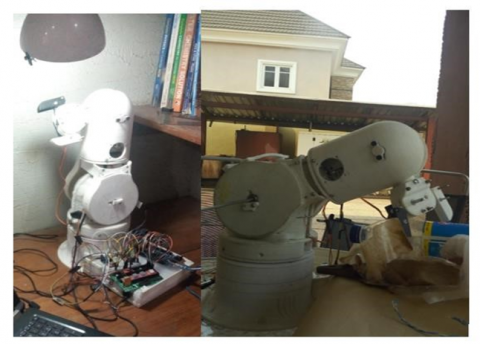
Figure 13. Experimental setup of UIArm robotic sorting system
Table 2. Joint parameters of UIArm Robot Arm
|
Joint |
Axis of rotation |
The angle of rotation (°) |
|
1 |
Z |
360 |
|
2 |
Y |
120 |
|
3 |
Y |
10 |
|
4 |
Z |
360 |
3.1 Experimentation
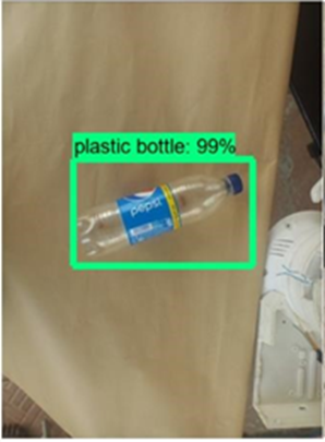
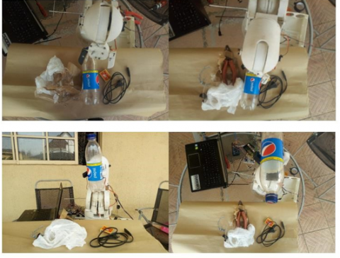
The custom-built TensorFlow object detection model achieved an accuracy of 99% for detecting Pepsi plastic bottles when tested with an only plastic bottles in the waste stream without other items (Figure 14). But when tested with other items in the waste stream, an accuracy of 91% detection for Pepsi bottles was achieved. However, other types of plastic bottles such as Coca-Cola, Fanta, etc. were detected with 85% accuracy. The high percentage accuracy for the detection of Pepsi plastic bottles may be due to the larger percentage of Pepsi plastic bottles used in the training of the model. The quality of the video feed significantly affects the accuracy and so a 720p camera was used which improved detection slightly. This increase in resolution however led to an increase in processing time and so a balance at 800 by 600-pixel resolution was chosen. Ten samples were tested with the plastic bottles partially covered up to 50% and the arm was able to identify and pick up 6 correctly. Significant difficulties were faced due to the wear of poorly printed parts [24]. The speed of movement was kept slow to avoid jerking motion which could cause unwanted forces within the structure. Figure 15 depicts the experimentation with the designed robotic sorting system.
Figure 14. Detection of Pepsi plastic bottle by the TensorFlow object detection model
Figure 15. Experimentation with UIArm I robotic arm sorting system
The developed model, UIArm I, is a custom built affordable, reliable, 3D printable, low-cost, and modular 4-degree-of-freedom robotic arm for automated sorting of plastic bottles from the waste stream. The object detection model achieved an accuracy ranging from 85 - 91% accuracy. The study has provided the platform for pushing the limits of robotics research and an avenue for alleviating the menace of plastic pollution in Nigeria. This is the pioneering effort of the Automation and Robotic laboratory of the Faculty of Technology, University of Ibadan, with great potential that can be scale-up, modified, and trained to accomplish complex tasks. In the nearest future, we look forward to having more robust robotic hands with great capabilities.
The authors extend their appreciation to the Founder and Management of Afe Babalola University; Ado Ekiti for the payment of Article Processing Charges (APC) of this manuscript.
[1] Strategy, P. (2018). A European strategy for plastics in a circular economy. Communication from the Commission to the European Parliament, the Council, the European Economic and Social Committee and the Committee of the Regions. Brussels, 12. https://www.europarc.org/wp-content/uploads/2018/01/Eu-plastics-strategy-brochure.pdf.
[2] Geyer, R., Jambeck, J.R., Law, K.L. (2017). Production, use, and fate of all plastics ever made. Science Advances, 3(7): e1700782. https://doi.org/10.1126/sciadv.1700782
[3] Atlas, P. (2019). Facts and figures about the world of synthetic polymers. Heinrich Böll Foundation, Berlin.
[4] Plastic Soup Foundation. (2017). There is plastic everywhere. https://www-plasticsoupfoundation-org.translate.goog/?_x_tr_sl=nl&_x_tr_tl=en&_x_tr_hl=en&_x_tr_pto=sc.
[5] Bogue, R. (2019). Strong prospects for robots in retail. Industrial Robot: International Journal of Robotics Research and Application, 46(3): 326-331. https://doi.org/10.1108/IR-01-2019-0023
[6] Goldstein. (2019). Global waste sorting robots market. Retrieved from: https://www.goldsteinresearch.com/report/global-wastesorting-robots-market
[7] Diya, S.Z., Proma, R.A., Islam, M.N., Anannya, T.T., Al Mamun, A., Arefeen, R., Rabbi, M.F. (2018). Developing an intelligent waste sorting system with robotic arm: A step towards green environment. The International Conference on Innovation in Engineering and Technology (ICIET), pp. 1-6. https://doi.org/10.1109/CIET.2018.8660890
[8] Noshahi, S.F., Farooq, A., Irfan, M., Ansar, T., Chumuang, N. (2019). Design and fabrication of an affordable scara 4-dof robotic manipulator for pick and place objects. In 2019 14th International Joint Symposium on Artificial Intelligence and Natural Language Processing (iSAI-NLP), pp. 1-5. https://doi.org/10.1109/iSAI-NLP48611.2019.9045203
[9] Wang, X., Guo, L. (2012). Highway traffic video detection method. Journal of Computer Applications, 32(6): 1585-1588.
[10] Wilts, H., Garcia, B.R., Garlito, R.G., Gómez, L.S., Prieto, E.G. (2021). Artificial intelligence in the sorting of municipal waste as an enabler of the circular economy. Resources, 10(4): 28. https://doi.org/10.3390/resources10040028
[11] Chang, Z., Hao, L., Tan, H., Li, W. (2020). Design of mobile garbage collection robot based on visual recognition. In 2020 IEEE 3rd International Conference on Automation, Electronics and Electrical Engineering (AUTEEE), pp. 448-451. https://doi.org/10.1109/AUTEEE50969.2020.9315545
[12] Angel, L.M. (2017). Thor public. DIY 3D printable robotic arm. https://github.com/AngelLM.
[13] Delfosse, Q., Stark, S., Tanneberg, D., Santucci, V.G., Peters, J. (2019) Open-ended learning of grasp strategies using intrinsically motivated self-supervision. https://www.ai.rug.nl/oel/papers/open_ended_grasping_OEL.pdf.
[14] Kakde, Y., Bothe, N., Paul, A. (2019). Real life implementation of object detection and classification using deep learning and robotic arm. Proceedings of Recent Advances in Interdisciplinary Trends in Engineering & Applications (RAITEA). https://papers.ssrn.com/sol3/papers.cfm?abstract_id=3372199
[15] Costa, J., Machado, T.A.U., Carneiro, M. (2020). Implementation and validation of Thor 3D printed open source robotic arm. IEEE Latin America Transactions, 18(05): 907-913. https://doi.org/10.1109/TLA.2020.9082919
[16] Ibarra-Pérez, T., Martínez-Blanco, M.D.R., Olivera-Domingo, F., Ortiz-Rodríguez, J.M., Gomez-Escribano, J. (2021). A novel optimization robust design of artificial neural networks to solve the inverse kinematics of a manipulator of 6 DOF. In 2021 22nd IEEE International Conference on Industrial Technology (ICIT), pp. 838-843. https://doi.org/10.1109/ICIT46573.2021.9453701
[17] Ko, D., Lee, S., Park, J. (2021). A study on manufacturing facility safety system using multimedia tools for cyber physical systems. Multimedia Tools and Applications, 80: 34553-34570. https://doi.org/10.1007/s11042-020-09925-z
[18] Fallas-Hernández, E. (2021). Diseno de entorno robótico como herramienta para el desarrollo de arquitecturas cognitivas. https://repositoriotec.tec.ac.cr/handle/2238/13269.
[19] Fallas-Hernández, E., Baldares, R.J., Crespo, J.L. (2021). OSCAR: A low-cost, open-source robotic platform design for cognitive research. In 2021 IEEE 3rd International Conference on BioInspired Processing (BIP), Cartago, Costa Rica, pp. 1-6. https://doi.org/10.1109/BIP53678.2021.9612905
[20] Abadi, M., Agarwal, A., Barham, P., Brevdo, E., Chen, Z., Citro, C., Zheng, X. (2016). Tensorflow: Large-scale machine learning on heterogeneous distributed systems. arXiv preprint, arXiv:1603.04467. https://arxiv.org/abs/1603.04467
[21] Adediran, E.M. (2020). Improved design and construction of a robot arm. An unpublished B.Sc. project report submitted to the Department of Mechanical Engineering, Faculty of Technology, University of Ibadan, Nigeria.
[22] Tzutalin. (2015). LabelImg. Retrieved from GitHub: https://github.com/tzutalin/labelImg.
[23] Clothier, K.E., Shang, Y. (2010). A geometric approach for robotic arm kinematics with hardware design, electrical design, and implementation. Journal of Robotics, 2010: 984823. https://doi.org/10.1155/2010/984823
[24] Semasinghe, C.L., Ranaweera, R.K.P.S., Prasanna, J.L.B., Kandamby, H.M., Madusanka, D.K., Gopura, R.A.R.C. (2018). HyPro: A multi-DoF hybrid-powered transradial robotic prosthesis. Journal of Robotics, 2018: 1-15. https://doi.org/10.1155/2018/8491073