Yanti Andriyani* | Ibnu Daqiqil Id | Evfi Mahdiyah | Al Aminuddin
© 2022 IIETA. This article is published by IIETA and is licensed under the CC BY 4.0 license (http://creativecommons.org/licenses/by/4.0/).
OPEN ACCESS
The Use Case Diagram (UCD) is a visual form of system design that helps software developers comprehend the system behavior. Maintaining and updating the system can be a difficult task when it has no visualization of a system behavior or software requirement specification document. Reverse engineering is an approach used to extract software requirement specifications from the existing systems. Research in reverse engineering has shown various techniques in which the processes are not fully understood. This study analyzes the University Community Services Information System (UCSIS) as the existing system in three processes: identifying the system domain process, elaborating system features by implementing the event table, and constructing the use case realization. The results showed that a UCD could be generated through the reverse engineering process on the existing system. Furthermore, a new feature for system improvement can also be detected using this method. It is expected that the reverse engineering approach in this study can be used as guidance for the software development team in extracting the use case diagram from the existing systems.
reverse engineering, use case diagram, event table, requirement specification
The software development process refers to a forward engineering approach, which follows sequential phases in developing software, such as analyzing feasibility, eliciting requirements, modelling system, coding development and implementation [1]. Each phase in the software development process generates outputs that are used for the next processes. For example, the requirement elicitation process generates specifications specified in software requirement specifications. The software specifications are also visualized in Use Case Diagram (UCD) [2, 3].
Identifying the UCD is an important task in the software development process to understand user requirements [4]. A UCD is a tool for modelling a system because it provides a coherent story about how it works [5]. This diagram provides a comprehensive summary of the system functions or a list of system functions that define the interactions between an actor and a system to achieve a goal. Furthermore, this diagram also provides a forum for domain experts, end-users, and developers to communicate. Practically, software teams are not always encountering an ideal situation. For example, insufficient system requirement specifications in the software development. This situation can be an obstacle for software teams in maintaining and updating the implemented system [6, 7]. Software requirement specification that is visualized in the UCD, is highly required to maintain, and update the system [1]. In this situation, software teams need to extract UCD and the specification from the existing system.
Software reverse engineering is a backward process that includes extracting design artifacts, decomposing requirements, and recapturing or recreating the design [8]. One of the subareas of reverse engineering is design recovery. Design recovery in software reverse engineering focuses on observing the system to identify domain knowledge and system abstraction. The observation is useful to provide detailed information about what software does, how it performs, and why it must be performed [8].
Software reverse engineering is important to understand since the reverse engineering process is useful for software maintenance and improvement. Reverse engineering helps the software developer to understand the system. By understanding the existing system, which often has lack documentation, the software developer can identify areas of improvement in the system [1, 8].
Chikofsky and Cross [8] explained that the reverse engineering approach could be implemented by extracting a higher abstraction level of the existing systems. Furthermore, reverse engineering can be used to understand how a system works and transform static information, such as Graphical User Interface (GUI) into requirement specification. Wu et al. [9] and Dayton et al. [10] conducted studies to perform reverse engineering by generating modes from a screenshot and GUI prototype to identify system requirements. Furthermore, Ecgonine et al. [6] and Frangulas et al. [7] performed a reverse engineering approach by recording a website's behavior. The extracting process captures and analyses the requirements generated by the UML diagram which attempts to break down their work reversely.
Previous reverse engineering research explored various techniques for extracting higher-level design from the existing system. However, much of the studies focused on technical by using programming tools, and the techniques that underpin the reverse engineering process are not fully understood. Recently, various reverse engineering approaches using tools have been explored, such as applying natural language processing and heuristic rules [11], using text analysis to generate the diagram and developing a web application to decompose the system [12, 13]. Di Luca et al. proposed a website for reverse engineering (WARE), which provides features to generate use cases, sequences, and class diagrams [13]. This tool emphasizes using static code as input. Similarly, Shiferaw and Jena [14] focus on the code generator and java code to analyze and extract of the UML diagrams involved in the system. These studies can extract UCD when the systems’ source code of the system is available.
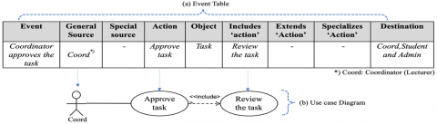
Another reverse engineering method, which uses the event table to generate UCD, was proposed by Muhairat and Al-Qutaish [15]. The event table is a basic table with four elements: event, source of event, action, and object. The basic event table is then extended into nine elements: event, general source, special source, action, object, includes 'action', extends 'action', specializes 'action' and destination.
However, much of the research has been descriptive in generating diagrams based on the availability of the source code, and the extracting process of the UCD remains unclear [1]. Furthermore, this study aims to analyze University Community Services Information System (UCSIS) as the existing system. A reverse engineering approach was applied to decompose UCSIS’ system requirement by implementing the extended event tables [15] in the analysis process. The event table is used in this paper as a fundamental to analyze the system behaviors and to generate the UCD. An important outcome of this paper is the system requirement in the form of a UCD.
The remaining part of the work proceeds as follows: Section 2 discusses the research method used: a case study and the method. Section 3 explains the results and discussion, which presents a case study on the proposed approach and discusses the results. Finally, Section 4 concludes the work and presents potential future work.
2.1 Data collection
This case study was conducted to elaborate on the existing University Community Services Information System (UCSIS). UCSIS is a system to manage community service programs that involving lecturers and students. The existing system needs an improvement to fulfill the updated processes. Thus, UCSIS requires improving and updating the system features. However, in this case, UCSIS does not have software requirement documentation and we perform reverse engineering to identify the existing system requirements and identify the system features that are required to be improved.
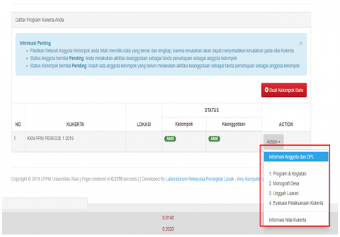
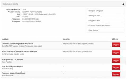
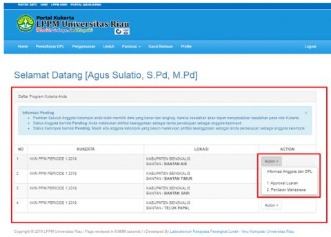
Several examples of UCSIS Portal user interfaces are presented in Figure 1, Figure 2, Figure 3. These forms were used as inputs to the capturing process of our proposed approach.
2.2 Reverse analysis processes
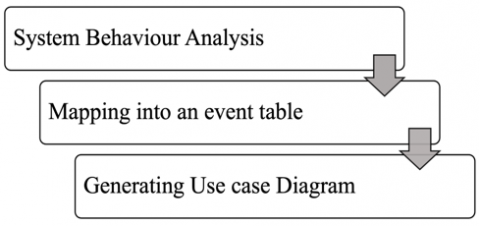
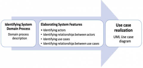
This study aims to generate UCD of the existing system using a reverse engineering approach. This research is conducted by implementing three processes (Figure 4). First, the existing system behaviors (i.e., UCSIS) were analyzed by observing users (i.e., admin, students, lecturer) in using the UCSIS. The researcher, who observed the system flows, wrote the system behaviors as scenarios, and broke them down into events.
Figure 1. UCSIS interface (Program management page)
Figure 2. UCSIS interface (The page for uploading the task output)
Figure 3. UCSIS interface (Approval page)
Figure 4. Reverse analysis processes
Figure 5. The mapping to event table process
The Events were identified by analyzing the system behaviors based on each process scenario based on user stories. Sequentially, the user stories were mapped into the event table. The following statement was an example of a user story captured from the system features analysis and mapped into the event table.
(User story) event #1:
As a coordinator, I want to be able to review the uploaded task, so that I can approve the uploaded task output
Broken down to:
Event : Coordinator approves the task output
General source : Coordinator
Special source : -
Action : Approve task
Object : The task
Includes 'action' : Review the task
Extends 'action' : -
Specializes 'action' : -
Destination : Coordinator, Student and Admin
The example of the event mapping into the even table can be seen in Figure 5. After mapping the event table, the next process was identifying the correlations of the attributes in the event table to generate a UCD.
Reverse engineering approach was used to generate UCD in our case study, University of Riau’s UCSIS Portal. There are three processes in generating UCD. The following sections explain the results of our reverse engineering approach.
3.1 Identifying system domain process
Identifying the process aims to capture the whole picture of the system. Domain processes were captured from observing the processes of the community service program. The community service program was announced at the beginning of semester. The process began with students and lecturers registering to join the community service program, managing the team and allocating students and lecturers to areas or villages.
The UCSIS's portal functions to manage community services projects at the University of Riau. UCSIS involves three system users: admin, lecturer, and student. The admin acts as a super administrator who can manage all data involved in the community service project. The lecturer acts as a coordinator allocated to village or sub-districts. The team coordinator was used in this case study to represents a lecturer supervising and coordinating a team. Student is a user that is responsible for working programs and tasks. Each student requires to report their activities to UCSIS.
Table 1 shows the domain processes of the UCSIS based on system behaviors analysis. The description of each domain process is presented in Table 1. There were four domain processes identified: community service management, registration, work program management, and grade management process. Work program validation is the new domain process that was not covered in the existing system. This domain process involves Community Service staff to validate the work program was performed by the students.
Table 1. Domain process descriptions
|
Process |
Description |
|
Community service management |
This process focuses on managing the data involved in the community service project, such as coordinators, students, villages, teams, work programs, period, and students report. |
|
Registration |
This process focuses on managing process for student and lecture registrations. |
|
Work program management |
This process involves students in managing the work programs, tasks, task outputs and reports. This process also involves coordinator approving working programs, task outputs and students' report. |
|
Grade management |
This process involves coordinator in grading the students’ tasks. |
|
Work program validation |
This process focuses on validation process of student’s work validation. There are three actors involved: coordinators, stakeholders, and Community Service Staff (CS staff). |
3.2 Identifying system features
The second process is elaborating system features. System features were identified by analyzing UCSIS’s portal behaviors and mapped into the event table.
3.2.1 Identifying use case diagram elements from the event table
This process aims to identify each use case elements and its relationships. There are four processes involved, such as:
(1) Identifying actors. In this process, the user’s system was defined as a source in an event table. Based on the system analysis, there are three actors included in UCSIS, such as: admin, coordinator, and student.
(2) Identifying relationships between actors aims to identify the association between the identified actors from the previous process. The embodied relationships between actors can be in the form of generalization or specialization. Generalization and specialization between actors do not always exist. If an actor exists in the special source, it means there is a relationship between the actor in the general source. In the case study, the generalization/specialization between actors are not available. The relationships between actors (i.e., generalization and specialization) may depend on the level of the system users and the complexity of the system.
(3) Identifying the use cases focuses on defining the use case derived from the domain process. The domain process provides general scenarios of a system that captures the system or subsystem behaviors. In this process, the captured behaviors are defined as an action. In UML it is represented as a use case symbol. Based on the identification, there are 20 use cases which 8 use cases related to Admin, 4 use cases related to coordinator and 7 use cases related to student.
(4) Identifying relationships between use cases aims to identify the association between the identified use cases from the previous process. The embodied relationships between use cases depends on include' action', extends 'action' and specializes 'action' in the event table. In addition, include 'action' is the action that is included in the base use case, and it is mandatory to operate the base use case. The Extend 'action' is the action that is included in the base action, and it is mandatory to operate the base action before the include' action'. Specialization' action' is the sub-action of the base action. Based on the identification, the admin has 2 inclusions and 3 extends relationships. Coordinator has 2 inclusions and 3 extends relationships. Student has 3 inclusions and has no extends relationships. In the case study, the specializes 'action' is not available. Therefore, in the UCD, there is no generalization and specialization relationship between use cases.
3.3 Use case diagram realization
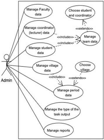
The final process is use case realization. Use case realization embodies the UCD based on the actors, use cases, and the relationships identified from the previous process. This process generates two UCDs and one diagram is a UCD with an additional scenario based on the updated process. Figure 6 and Figure 7 show the result of use case integration based on the relationships based on Table 2, Table 3, and Table 4.
Table 2. Event table generated from system behaviour and elaboration of system domain process (Admin)
|
Event |
General Source |
Special Source |
Action |
Object |
Includes 'Action' |
Extends 'Action' |
Specializes 'Action' |
Destination |
|
Admin manages coordinator data |
Admin |
- |
Manage coordinator data |
Coordinator data |
- |
- |
- |
Admin |
|
Admin manages faculty data |
Admin |
- |
Manage faculty data |
Faculty data |
- |
- |
- |
Admin |
|
Admin manages student data |
Admin |
- |
Manage student data |
Student data |
- |
- |
- |
Admin |
|
Admin manages the type of work program's output |
Admin |
- |
Manage the type of work program's output |
The type of work program's output |
- |
- |
- |
Admin |
|
Admin manages villages data |
Admin |
- |
Manage village data |
Village data |
- |
- |
- |
Admin |
|
Admin manages period of community service program |
Admin |
- |
Manage period |
Period |
Manage village data |
Choose village |
- |
Admin |
|
Admin classifies students as a team and identify team's coordinator |
Admin |
- |
Manage teams’ data |
Students and coordinator data |
Manage student and coordinator data |
Choose students and coordinator |
- |
Admin, student, Coord |
|
Admin manages the reports |
Admin |
- |
Manage reports |
Reports |
- |
- |
- |
Admin |
Table 3. Event table generated from system behaviour and elaboration of system domain process (Coordinator)
|
Event |
General Source |
Special Source |
Action |
Object |
Includes 'Action' |
Extends 'Action' |
Specializes 'Action' |
Destination |
|
Coordinator manage teams |
Coord |
- |
View team members |
Team members |
- |
- |
- |
Coord |
|
Coordinator views and approves the task output |
Coord |
- |
View the task output |
The task output |
Upload the task output |
Approval the task output |
- |
Coord, Student, Admin |
|
Coordinator views and approves the final report |
Coord |
- |
View the final report |
The final report |
Upload the final report |
Approval the final report |
- |
Coord, Student, Admin |
|
Coordinator grades the final reports |
Coord |
- |
Add student grades |
Student grades |
- |
Print student grades report |
- |
Coord, Admin, Student |
Table 4. Event table generated from system behavior and elaboration of system domain process (Students)
|
Event |
General Source |
Special Source |
Action |
Object |
Includes 'Action' |
Extends 'Action' |
Specializes 'Action' |
Destination |
|
Student makes a registration |
Student |
- |
Make a registration |
Registration |
Upload documents required |
- |
- |
Student |
|
Student makes a registration |
Student |
- |
Make a registration |
Registration |
Update profile |
- |
- |
Student |
|
Student views team members and coordinator |
Student |
- |
View team members and coordinator |
Team members |
- |
- |
- |
Student |
|
Student manages work program for their team |
Student |
- |
Manage work program data |
Work program |
Manage task in work program |
- |
- |
Student |
|
Student manages task for their team |
Student |
- |
Manage task in work program |
Task |
- |
- |
- |
Student |
|
Student manages village profile |
Student |
- |
Manage village profile |
Village profile |
- |
- |
- |
Student |
|
Student upload the task report |
Student |
- |
Upload the task report |
The task report |
- |
- |
- |
Student |
|
Student upload the final report |
Student |
- |
Upload the final report |
The final report |
- |
- |
- |
Student |
Table 5. Event table generated from new domain process (Community Service Division/Staff)
|
Event |
General Source |
Special Source |
Action |
Object |
Includes 'Action' |
Extends 'Action' |
Specializes 'Action' |
Destination |
|
CS staff view the task output |
CS Staff |
- |
Validation the task output |
The task output |
Upload the task output |
Validate the task output |
- |
Coordinator and Student |
|
CS staff view the final report |
CS Staff |
- |
Validation the final report |
The final report |
Upload the final report |
Validate the final report |
- |
Coordinator and Student |
Figure 6. UCD derived from the event table (admin)
Figure 7. UCD derived from the event table (student and coordinator) based on the existing system
Figure 8. Improved UCD by adding new process
This process also visualizes the areas of improvement to show the features required to be added to the UCSIS. Table 5 describes the scenario of the additional domain process into the event table. As shown in Figure 7, there is no CS staff (Community Service staff) in the UCD. The new use case is generated based on the additional domain process and the mapping on the Table 5 (Figure 8). Figure 8 Shows the areas of improvement (using red line) in the form of UCD. Visualizing the new UCD shows that there are requirements to add menu for CS staff to view the task output and final report to validate the task output and final report.
3.4 Discussion
The findings related to the reverse engineering approach were discussed and it was reported that there are three processes needed to be included in extracting UCD for the system that the source code is not available. A reverse engineering approach was presented by adding several processes and combining them with event table [15]. The processes are identifying the system domain process, elaborating system features, and use case realization.
Identifying the system domain process involves domain process descriptions. The domain process is considered as the initial process in this approach because it is a crucial aspect in software process [1-3]. Identifying the system domain process includes descriptions of the domain process. Furthermore, the domain process is considered as initial process in this approach because it is a crucial aspect in software process [2, 3]. Not all domain process of the software is well written and well understood. This study confirms that domain process in software engineering is associated with important knowledge in software development that can be reused [16, 17]. In addition, previous research has suggested that a reverse approach should be carried out directly and that the actors should be identified [15, 17].
This approach seems to work for generating UCD as well, but it can be difficult in specifying the details of the system behaviors when the domain process is not well understood. Adding domain process identification in the reverse engineering is useful as it is also an important aspect of the software development process [3, 18].
Elaborating system features process includes the process of creating an event table that consists of actors, use cases, the relationships between actors and the relationships between use cases identification. This process attempts to understand the higher-level abstraction of the system from the system behaviors. The addition of system features elaboration in the reverse engineering approach is in line with previous study [8]. As explained by Chikofsky & Cross [8], design recovery is part of the reverse engineering process, which focuses on observing the subject system from design documentation. The design recovery needs to produce all information related to details of system features and behaviors.
In the use case realization process, the output of the previous process is structured into UCD. This process is related to the restructuring sub-area in reverse engineering [8]. Restructuring is the transformation of software form to modelling form where the changes can be used as references for understanding the system or software modifications.
Previous studies focused on reverse engineering method, with little focus on how to extract UCD in reverse engineering approach for the software or system with no source code available. One of the key contributions of this work is to present a reverse engineering approach based on system behaviors without no access to the source code. The reverse engineering approach focuses on three processes and the integration of the event table into the processes.
In general, this study reiterates the idea that reverse engineering should be able to provide high level system abstraction even when the source code is not available. The proposed reverse engineering approach applied in this research integrates an extended event table and the process in the requirement engineering. As depicted in Figure 9, the proposed approach discussed in this research starts with identifying the domain process of the system, elaborating system features and use case realization. Identifying the domain process aims to specify the important processes of the existing system. By generating domain process descriptions, system features can be identified respectively.
The second stage of the reverse engineering approach is elaborating system features. Elaborating system features focuses on system details from the actors, use cases, and relationships. By having detail of the system, software developers can visualize the UCD. The UCD generated from the reverse engineering process would be useful for identifying areas for improvement of the system features.
Figure 9. Reverse engineering approach to extract UML use case diagram
This research implies that the results shows that the approach presents a new reverse engineering strategy to generate a UCD using system behaviors analysis. Software practitioners, such as software developers, business analysts, system analyst or software project managers, can use this approach to elaborate software requirement specifications without source code. In the future work, this approach can be further analyzed and extended to other UML diagrams, such as class, activity, sequence diagrams and their relationship.
This research is supported and funded by Lembaga Penelitian dan Pengabdian Masyarakat (LPPM) University of Riau with the contract number: 702/UN.19.5.1.3/PT.01.03/2021.
[1] Canfora, G., Di Penta, M., Cerulo, L. (2011). Achievements and challenges in software reverse engineering. Communications of the ACM, 54(4): 142-151. https://doi.org/10.1145/1924421.1924451
[2] Dingle, A. (2021). Object-Oriented Design Choices. First edition. | Boca Raton: CRC Press, Chapman and Hall/CRC, 2021. https://doi.org/10.1201/9781003013488
[3] O’Regan, G. (2018). Object-oriented paradigm. In the Innovation in Computing Companion, Cham: Springer International Publishing, 213-215. https://doi.org/10.1007/978-3-030-02619-6_45
[4] Sabir, U., Azam, F., Haq, S.U., Anwar, M.W., Butt, W.H., Amjad, A. (2019). A model driven reverse engineering framework for generating high level UML models from java source code. IEEE Access, 7: 158931-158950. https://doi.org/10.1109/ACCESS.2019.2950884
[5] Fowler, M. (2004). UML Distilled: A Brief Guide to The Standard Object Modeling Language. Addison-Wesley Professional, 2004.
[6] Čeponienė, L., Drungilas, V., Jurgelaitis, M., Čeponis, J. (2018). Method for reverse engineering UML use case model for websites. Inf. Technol. Control., 47(4): 623-638. https://doi.org/10.5755/j01.itc.47.4.21264
[7] Drungilas, V., Čeponienē, L., Jurgelaitis, M. (2018). Reverse engineering of UML use case model from website usage records. In International Conference on Information Technologies, IVUS., pp. 54-60.
[8] Chikofsky, E.J., Cross, J.H. (1990). Reverse engineering and design recovery: A taxonomy. IEEE Software, 7(1): 13-17. https://doi.org/10.1109/52.43044
[9] Wu, J., Zhang, X., Nichols, J., Bigham, J.P. (2021). Screen parsing: Towards reverse engineering of UI models from screenshots. In the 34th Annual ACM Symposium on User Interface Software and Technology, pp. 470-483. https://doi.org/10.1145/3472749.3474763
[10] Dayton, T., Mcfarland, A., Kramer, J. (2018). Bridging user needs to object oriented GUI prototype via task object design. In User Interface Design, CRC Press, 15-56.
[11] Abdelnabi, E.A., Maatuk, A.M., Abdelaziz, T.M., Elakeili, S.M. (2020). Generating UML class diagram using NLP techniques and heuristic rules. In International Conference on Sciences and Techniques of Automatic Control and Computer Engineering (STA), 130: 277-282. https://doi.org/10.1109/STA50679.2020.9329301
[12] Narawita, C.R., Vidanage, K. (2018). UML generator – use case and class diagram generation from text requirements. International Journal on Advances in ICT for Emerging Regions (ICTer), 10(1): 1. https://doi.org/10.4038/icter.v10i1.7182
[13] Di Lucca, G.A., Fasolino, A.R., Tramontana, P. (2004). Reverse engineering Web applications: the WARE approach. Journal of Software Maintenance and Evolution Research and Practice, 16(12): 71-101. https://doi.org/10.1002/smr.281
[14] Shiferaw, M.K., Jena, A.K. (2018). Code generator for model- driven software development using UML models. In Second International Conference on Electronics, Communication and Aerospace Technology (ICECA), pp. 1671-1678. https://doi.org/10.1109/ICECA.2018.8474690
[15] Muhairat, M.I., Al-Qutaish, R.E. (2009). An approach to derive the use case diagrams from an event table. Conference: Proceedings of the 8th International Conference on Software Engineering, Parallel and Distributed Systems (SEPADS'09). At: University of Cambridge, Cambridge, UK.
[16] Oveh, R.O., Egbokhare, F.A. (2019). Harvesting and informal representation of software process domain knowledge. In Intelligent Computing-Proceedings of the Computing Conference, 2019, pp. 936-947.
[17] Osis, J., Donins, U. (2017). Topological UML modeling: An improved approach for domain modeling and software development. Elsevier, 2017.
[18] Ivanova, L.S., Sokolov, D.A., Zmeev, O.A. (2021). UML representation of object-oriented design antipatterns. in 2021 International Conference on Information Technology (ICIT), pp. 98-103. https://doi.org/10.1109/ICIT52682.2021.9491660