OPEN ACCESS
The traditional camera calibration methods faces many problems, such as the need for manual operation and high-quality images as well as the heavy time consumption. To solve these problems, this paper puts forward an adaptive extraction and matching algorithm for checkerboard inner-corners for camera calibration. Firstly, the coordinates of all corner points of the checkerboard were derived by the Harris algorithm. Then, the four vertices of the checkerboard were acquired in the image coordinate system based on polygonal convexity. After that, the coordinates of the inner-corner points of the checkerboard image were obtained against the judgement rules that distinguish inner-corner points from other points on that image. On this basis, the matching relationship was established between the inner-corner points of the checkerboard image in the image coordinate system and those in the checkerboard coordinate system. Finally, the theoretical modelling, judgement rules and a mature camera calibration model were integrated for automatic camera calibration experiments. The results show that the automatic camera calibration method based on the proposed algorithm consumed 75% less time than the Matlab toolbox and controlled the error within ±0.3 pixels. This research provides a real-time, robust and accurate automatic camera calibration method for engineering applications.
computer vision, camera calibration, checkerboard, corner recognition, corner matching
Camera calibration is the key to the extraction of size, topography and other information from 2D images (Engel et al., 2016). The calibration accuracy directly bears on the measurement precision of the vision measurement system (Bushnevskiy et al., 2016). By the calibration principle, the existing methods for camera calibration can be divided into three categories, namely, self-calibration, active vision calibration and traditional camera calibration. Self-calibration (Baataoui et al., 2014) and active vision calibration are simple and flexible and need no calibration object. However, these two types of methods are suitable for online calibration only, due to the low precision (Jin and Li, 2013). By contrast, traditional camera calibration (Zhang, 2000; Huang et al., 2006)requires a calibration object and can achieve a high precision. With mature camera imaging models and optimization algorithms, the traditional camera calibration methods have been widely used in industrial applications which demand high accuracy and forbid post-calibration adjustment of camera parameters (Hou and Wang, 2012). As a result, traditional camera calibration methods, coupled with calibration object, are preferred for camera calibration in vision measurement systems.
The precision and efficiency of traditional camera calibration depend not only on the accuracy of the calibration object, but also the feature extraction and matching algorithms for the object. Most algorithms for traditional camera calibration are developed for machine vision industrial applications. For example, the checkerboard-based calibration algorithm enjoys good stability, but relies on manual assistance in many operations (e.g. selecting the inner corners). The accuracy of this algorithm can be improved using multiple images, but the improvement comes at the price of simplicity and timeliness (Krüger & Wöhler, 2011; Leal-Taixé et al., 2012). The calibration algorithms using the circular calibration plate can realize a high degree of automation (Wei and Ma, 1991; Shan et al., 2016), only if the images are of high quality. Otherwise, it is difficult for these algorithms to complete the task (Liu & Shang, 2013).
Recent years has seen the emergence of many other camera calibration methods, each of which has its merits and defects. Harris and Smith created an efficient and stable algorithm that can extract corner point coordinates of the checkerboard (Harris, 1988), but failing to extract the coordinates of the outer-corner point every accurately. The smallest univalue segment assimilating nucleus (SUSAN) algorithm cannot effectively distinguish the inner-corner (X-shaped corner) (Smith & Brady, 1997). Yang et al., (2010), (Hai et al., 2015)proposed a corner detection algorithm to solve the defect of the SUSAN algorithm. In Yang’s algorithm, the position of the X-shaped corner of the checkerboard is roughly determined by the small neighborhood gray-scale changes of ring template, and then the corner points are accurately positioned by Harris corner response function. However, this algorithm has a high false detection rate for corner points. Zhang (2014) designed a special detection template to identify or extract corner points according to the grayscale distribution or geometry of the checkerboard corner points. This template performs well in the detection of specific checkerboard corners, but only works for high quality images. Geiger et al., (2012) developed an integrated method for comprehensive detection of various diagonal feature points. Despite its good applicability, Geiger’s method is too complicated and often beats around the bush.
According to the above analysis, the existing extraction and matching methods for checkerboard features in camera calibration have many inadequacies. The robustness and accuracy of these methods need to be improved to realize efficient and automatic camera calibration. Therefore, this paper probes deep into checkerboard-based camera calibration, and realizes that the efficiency and automation of this calibration strategy hinges on the adaptive extraction of the exact corner points and the automatic matching of corner points between the image and the calibration object. In light of these, the author put forward an adaptive extraction and matching algorithm for checkerboard inner-corners for camera calibration through the following steps. First, the coordinates of all corner points of the checkerboard were derived by the Harris algorithm. Second, the four vertices of the checkerboard were acquired in the image coordinate system based on polygonal convexity. Third, the coordinates of the inner-corner points of the checkerboard image were obtained against the judgement rules that distinguish inner-corner points from other points on that image. Fourth, the matching relationship was established between the inner-corner points of the checkerboard image in the image coordinate system and those in the checkerboard coordinate system. After that, the theoretical modelling, judgement rules and a mature camera calibration model were integrated for automatic camera calibration experiments, aiming to verify the correctness of the proposed algorithm.
The remainder of this paper is organized as follows: Section 2 introduces the composition and mechanism of automatic camera calibration system; Section 3 explains the functions of the proposed algorithm, such as the extraction of checkerboard corners, the recognition of checkerboard outer vertices, the identification of inner-corners of the checkerboard, and the matching of the inner-corners; Section 4 verifies the proposed algorithm through contrastive experiments; Section 5 wraps up this research with several conclusions.
This section explains the checkerboard-based camera calibration process. Starting with the composition of the automatic camera calibration system, the author pointed out the problems in the extraction of checkerboard corners, and combined the proposed algorithm for automatic camera calibration with a mature camera calibration model.
2.1. Composition of automatic camera calibration system
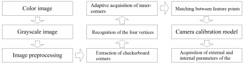
As shown in Figure 1, the automatic camera calibration system consists of a detection platform, a checkerboard, a camera, an image acquisition card, a computer and so on. During the automatic calibration, the checkerboard posture in the calibration plane is adjusted manually so that it always falls in the camera’s field of view. The images of checkerboard at different postures are acquired by the camera and sent to the computer, where they are processed by mathematic modelling and corresponding algorithms.
Figure 1. Composition of the automatic camera calibration system
2.2. Mechanism of automatic camera calibration system
The automatic camera calibration system mainly acquires the external and internal parameters of the camera. The external parameters depict the camera position and orientation in the 3D space, while the internal parameters reflect the distortion, mapping and error of the imaging process. The mapping relationship between the checkerboard coordinate system and the image coordinate system can be established based on the two types of camera parameters. Zhang et al. developed a camera calibration model based on the checkerboard, in which the camera shots multiple images of the checkerboard in different postures. Then, the mapping relationship between each feature point in checkerboard coordinate system and that in image coordinate system was established, and a single matrix of the single image was set up below for camera calibration:
$s\left[\begin{array}{l}{u} \\ {v} \\ {1}\end{array}\right]=A\left[\begin{array}{lll}{r_{1}} & {r_{2}} & {t}\end{array}\right]\left[\begin{array}{l}{X} \\ {Y} \\ {1}\end{array}\right]$ (1)
where A is the internal matrix; r1 and r2 are the column vectors of the rotation matrix; t is the translation matrix; (u, v) are the coordinates in image coordinate system; (X, Y) are the coordinates in checkerboard coordinate system. Zhang’s camera calibration method has a low accuracy in the recognition of inner-corners if all corners of the checkerboard are extracted by the traditional Harris algorithm (Figure 2). The inner-corners can be identified accurately by human-computer interaction in MATLAB calibration toolbox. However, the human-computer interaction is very inconvenient, because multiple images are often adopted to enhance the camera calibration accuracy.
Figure 2. Corner extraction results of Harris algorithm
Figure 3. Mechanism of checkerboard-based automatic camera calibration
In this paper, the checkerboard inner-corners are extracted in an intelligent and accuracy manner, before determining the mapping relationship between each feature point in checkerboard coordinate system and that in image coordinate system. This approach was combined with Zhang’s method into an automatic camera calibration method. The mechanism of our method is shown in Figure 3 below.
3.1. Extraction of checkerboard corners
It is widely accepted that checkerboard corners create sharp changes in brightness of grayscale images. The checkerboard corners can be identified by this law. The identification process is explained as follows [4,5].
(1) Let f (u, v) be the grayscale at the pixel whose coordinates are (u, v) in the image. Then, the grayscale at the pixel coordinates (u+Δu, v+Δv) in the image is f (u+Δu, v+Δv). The grayscale variation EΔu, Δv (u, v) can be expressed as:
$E \Delta u, \Delta v(u, v)=\sum_{\Delta u, \Delta v} w_{\Delta u, \Delta v} \times[\mathrm{f}(u+\Delta u, v+\Delta v)-\mathrm{f}(u, v)]^{2}$ (2)
where wΔu,Δv=exp(-0.5(u2+v2)/δ2) is a Gaussian operator to smooth the image and enhance the noise immunity of the algorithm.
(2) According to the above and the Taylor expansion, the grayscale variation EΔu, Δv (u, v) can be described by the differential operator:
$E \Delta u, \Delta v(u, v)=\sum_{\Delta t, \Delta v} w_{\Delta u, \Delta v}\left[\Delta u f_{u}+\Delta v f_{v}+o\left(\Delta u^{2}, \Delta v^{2}\right)\right]^{2}$
$\approx \sum_{\Delta u, \Delta v} w_{\Delta u, \Delta v}\left(\Delta u f_{u}+\Delta v f_{v}\right)^{2}$
$=\sum_{\Delta u, \Delta v}^{\Delta u, \Delta v} w_{\Delta u, \Delta v}\left(\Delta u^{2} f_{u}^{2}+\Delta v^{2} f_{v}^{2}+2 \Delta u \Delta v f_{u} f_{v}\right)$
$=\sum_{\Delta u, \Delta v} w_{\Delta u, \Delta v}\left((\Delta u, \Delta v)\left[\begin{array}{c}{f_{u}^{2} \quad f_{u} f_{v}} \\ {f_{u} f_{v} \quad f^2_v}\end{array}\right](\Delta u, \Delta v)^{T}\right)$ (3)
where fu, fv is the gradient of the primary grayscale.
(3) Let λ1and λ2 be the eigenvalues of matrix M=[fu2 fufv; fufv fv2]. If λ1and λ2 are small, then the target is a flat area; if only one of λ1and λ2 is small, then the target is an edge; if λ1and λ2 are equal, large integers, then the target is a checkerboard corner. Thus, the checkerboard corner extraction can be expressed as:
$H_{h a r i s}=\operatorname{det} M-k(\operatorname{tr} M)^{2}$ (4)
where detM=λ1λ2; trM=λ1+λ2; k is a positive constant (the general value is 0.4). The corresponding point is a corner when Hharris reaches the local maximum.
(4) The checkerboard corner extraction results of the above algorithm are presented in Figure 4, where the inner-corners are recognized more accurately than the outer-corners.
Figure 4. Corner extraction results
3.2. Identification of checkerboard vertices
Liu et al. proposed an extreme value theory to identify the vertices of simple polygons [4]: if the vertex value along the x-axis is small (large), the vertex must be the left (right) vertex of the simple polygon; if the vertex value along the y-axis is small (large), the vertex must be the top (down) vertex of the simple polygon. However, these rules cannot be applied easily when the checkerboard coordinate system is parallel to the image coordinate system. Considering the irregular posture changes of the checkerboard in the camera calibration process, the coordinates of the four outer-vertices in the image coordinate system were acquired adaptively through the following steps:
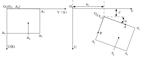
Step 1: The image coordinate system o1uvw was established assuming that the origin point o1 is the upper-left point in the image, the u-axis points to the horizontal direction, the v-axis points to the vertical direction, and the w-axis points to the normal of the u-v plane. The checkerboard coordinate system o2rst was established assuming that the origin point o2 is the upper-left corner of the checkerboard, the r-axis is along the straight line between the top-left corner and the top-right corner, the s-axis is along the straight line between the top-left corner and the lower-left corner, and the t-axis is along the normal of the r-s plane.
Step 2: If checkerboard coordinate system o2rst was completely coincided with the image coordinate system o1uvw (Figure 5(a)), then the coordinates of the four vertices in the image coordinate system o1uvw can be expressed as A′1(u1,v1), A′2(um,v1), A′3(um, vn) and A′4(u1,vn), respectively. Let A′ij(uij, vij) be the corner coordinates in the image coordinate system o1uvw. Note that i is the row number along the r-axis and j is the column number along the s-axis of the checkerboard; m is the maximum row number and n the maximum column number of the checkerboard; 1≤i≤m, 1≤j≤n; m, n, i and j∈Z. The checkerboard posture in this scenario was taken as the reference posture.
Step 3: If the checkerboard coordinate system o2rst was not coincided with the image coordinate system o1uvw and the checkerboard posture changed irregularly in the camera’s field of view (Figure 5(b)), then the real-time posture of the checkerboard relative to the reference posture can be described by the translation matrix T=[ax, ay, 0]T and the rotation matrix R=[0,0,θ]T, where 0≤ax, 0≤ay and -45≤θ≤45. Let εr and εs be the length of a square grid on the checkerboard along the r-axis and the s-axis in the checkerboard coordinate system o2rst, respectively. In this case, the coordinates of corner Aij(rij, sij) in the checkerboard coordinate system o2rst satisfy the following relationship:
$\left\{\begin{array}{l}{\mathbf{r}_{i j}=(i-1) \varepsilon_{r}=(i-1) \varepsilon} \\ {s_{i j}=(j-1) \varepsilon_{s}=(j-1) \varepsilon}\end{array}\right.$ (5)
Step 4: If the checkerboard coordinate system o2rst was not coincided with the image coordinate system o1uvw and the checkerboard posture changed regularly in the camera’s field of view, then the corner Aij(rij,sij) in the checkerboard coordinate system o2rst and the corresponding corner A´ij (uij,vij) in the image coordinate system o1uvw satisfy the following relationship:
$\left[\begin{array}{c}{u_{i j}} \\ {v_{i j}} \\ {1}\end{array}\right]=\left[\begin{array}{ccc}{1} & {0} & {a_{x}} \\ {0} & {1} & {a_{y}} \\ {0} & {0} & {1}\end{array}\right]\left(\left[\begin{array}{ccc}{\cos \theta} & {-\sin \theta} & {0} \\ {\sin \theta} & {\cos \theta} & {0} \\ {0} & {0} & {1}\end{array}\right]\left[\begin{array}{c}{r_{i j}} \\ {s_{i j}} \\ {1}\end{array}\right]\right)$ (6)
where
$\left\{\begin{array}{l}{u_{i j}=a_{x}+((j-1) \sin \theta+(i-1) \cos \theta) \varepsilon} \\ {v_{i j}=a_{y}+((j-1) \cos \theta-(i-1) \sin \theta) \varepsilon}\end{array}\right.$ (7)
The following can be derived from the above relationship:
$\left\{\begin{array}{l}{u_{i j}+v_{i j}=\left(a_{x}+a_{y}\right)+((\cos \theta-\sin \theta) i+(\sin \theta+\cos \theta) j-2 \cos \theta) \varepsilon} \\ {u_{i j}-v_{i j}=\left(a_{x}-a_{y}\right)+((\sin \theta+\cos \theta) i-(\cos \theta-\sin \theta) j-2 \sin \theta) \varepsilon}\end{array}\right.$ (8)
Since -45≤θ≤45, cosθ+sinθ≥0 and cosθ-sinθ≥0 and ax, ay, θ and ε are constant when the checkerboard is in a certain posture, we have:
(1) If i=1, j=1 and (uij+vij) reaches the minimum, then the corner A´ij(uij,vij) in the image coordinate system o2rst is the projection point of vertex A1 in the checkerboard coordinate system o1uvw;
(2) If i=m, j=n and (uij+vij) reaches the maximum, then the corner A´ij(uij,vij) in the image coordinate system o2rst is the projection point of vertex A3 in the checkerboard coordinate system o1uvw;
(3) If i=m, j=1and (uij-vij) reaches the maximum, then the corner A´ij(uij,vij) in image coordinate system o2rst is the projection point of vertex A4 in the checkerboard coordinate system o1uvw;
(4) If i=1, j=n and (uij-vij) reaches the maximum, then the corner A´ij(uij,vij) in image coordinate system o2rst is the projection point of vertex A2 in the checkerboard coordinate system o1uvw.
Figure 5. Identification of checkerboard vertices
The above analysis shows that the checkerboard vertices in the image coordinate system o1uvw satisfy the following rules:
$\mathrm{A}_{\mathrm{ij}}^{\prime}\left(\mathrm{u}_{\mathrm{ij}}, \mathrm{v}_{\mathrm{ij}}\right)=\left\{\begin{array}{ll}{A_{1},} & {\text {if} \quad\left(u_{i j}+v_{i j}\right)_{\min }} \\ {A_{2},} & {\text {if} \quad\left(u_{i j}-v_{i j}\right)_{\min }} \\ {A_{3},} & {\text {if} \quad\left(u_{i j}+v_{i j}\right)_{\max }} \\ {A_{4},} & {\text {if } \quad\left(u_{i j}-v_{i j}\right)_{\max }}\end{array}\right.$ (9)
According to equation (9), the checkerboard vertices were extracted in the image coordinate system o2rst by logical operation and recorded in Figure 6 below.
Figure 6. Extraction of checkerboard the vertices in image coordinate system o2rst
3.3. Recognition of inner-corner points of the checkerboard
After extracting the checkerboard vertices in the image coordinate system, the corner points of the checkerboard were extracted in image coordinate system o1uvw through the following steps.
Step 1: In the image coordinate system o1uvw, the four checkerboard vertices A´1, A´2, A´3 and A´4 were connected by two diagonal lines that intersects at point O. The two lines divide the checkerboard corners into four triangular areas: ΔOA´1A´2, ΔOA´2A´3, ΔOA´3A´4 and ΔOA´1A´4 (Figure 7).
Figure 7. Distribution of checkerboard vertices
Step 2: Let $\overrightarrow{A_{4} A_{3}}$ be the reference vector, $\overrightarrow{O A_{i}}$
is be the vector between corner point Ai and the intersecting point O and α be the angle between vector $\overrightarrow{O A_{i}}$ and vector $\overrightarrow{A_{4} A_{3}}$ . Then, the triangular area of the checkerboard inner-corner Ai can be determined as:$\mathrm{A}_{i} \in\left\{\begin{array}{ll}{\Delta O A_{2} A_{3}, \alpha} {\in\left(\alpha_{1}, \alpha_{2}\right)} \\ {\Delta O A_{1} A_{2}, \alpha} {\in\left(\alpha_{2}, \alpha_{3}\right)} \\ {\Delta O A_{1} A_{4}, \alpha \in\left(\alpha_{3},\right.} {\left.\alpha_{4}\right)} \\ {\Delta O A_{3} A_{4}, \alpha \in\left(\alpha_{4},\right.} {\left.\alpha_{5}\right)}\end{array}\right.$ (10)
where α1 is the angle between vector $\overrightarrow{O A_{3}}$ and vector $\overrightarrow{A_{4} A_{3}}$; α2 is the angle between vector $\overrightarrow{O A_{2}}$ and vector $\overrightarrow{A_{4} A_{3}}$; α3 is the angle between vector $\overrightarrow{O A_{1}}$ and vector $\overrightarrow{A_{4} A_{3}}$; α4 is the angle between vector $\overrightarrow{O A_{4}}$ and vector $\overrightarrow{A_{4} A_{3}}$; α5 is the angle between vector $\overrightarrow{O A_{3}}$ and vector $\overrightarrow{A_{4} A_{3}}$. These angles can be calculated as:
$ \left\{\begin{array}{rl}\alpha_{1}=\arctan \left(\frac{k_{\overline{O A_{3}}}-k_{\overline{A_{1} A_{3}}}}{1+k_{\overline{O A_{3}}} k_{\overline{A_{4} A_{3}}}}\right), k_{\overline{O A_{3}}}=\frac{v_{A_{3}}-v_{O}}{u_{A_{3}}-u_{O}}\\\alpha_{2}=\arctan \left(\frac{k_{\overline{O A_{2}}}-k_{\overline{A_{4} A_{3}}}}{1+k_{\overline{O A_{2}}} k_{\overline{A_{4} A_{3}}}}\right), k_{\overline{O A_{2}}}=\frac{v_{O}-v_{A_{2}}}{u_{A_{2}}-u_{O}}\\\alpha_{3}=\arctan \left(\frac{k_{\overline{O A_{1}}}-k_{\overline{A_{4} A_{3}}}}{1+k_{\overline{O A_{1}}} k_{\overline{A_{4} A_{3}}}}\right), k_{\overline{O A_{1}}}=\frac{v_{O}-v_{A_{1}}}{u_{O}-u_{A_{1}}}\\\alpha_{4}=\arctan \left(\frac{k_{\overline{O A_{1}}}-k_{\overline{A_{4} A_{3}}}}{1+k_{\overline{O A_{4}}} k_{\overline{A_{4} A_{3}}}}\right), k_{\overline{O A_{4}}}=\frac{v_{A_{4}}-v_{O}}{u_{O}-u_{A_{4}}}\\\alpha_{5}=\arctan \left(\frac{k_{\overline{A_{1} A_{3}}}-k_{\overline{O A_{3}}}}{1+k_{\overline{O A_{3}}} k_{\overline{A_{4} A_{3}}}}\right), \quad \alpha_{1}+360=\alpha_{5}\end{array} \right. $ (11)
where
$\left\{\begin{array}{l}{u_{o}=\frac{1}{4}\left(u_{A_{1}}+u_{A_{2}}+u_{A_{3}}+u_{A_{4}}\right)} \\ {v_{O}=\frac{1}{4}\left(v_{A_{1}}+v_{A_{2}}+v_{A_{3}}+v_{A_{4}}\right)}\end{array}\right.$ (12)
Step 3: The straight line equation Li0 was calculated according to points according to the two vertices of the local triangular area of corner Ai, as well as point O and point Ai. Let Ai0(uAi0, vAi0) be the intersecting point between straight lines Li and Li0 (Figure 7).
Step 4: The lengths of segments OAi0 and OAi were compared according to the coordinates of points O, Ai0 and Ai in the image coordinate system. The comparison results help to determine whether a corner is an inner-corner. Let R and L be the lengths of segments OAi and OAi0, respectively. The judgement rules can be expressed as: If When R<L-ξ, point Ai is an inner-corner; otherwise, point Ai is an outer-corner. Note that ξ is the tolerance (pixel). Previous experiment shows that the value of ξ is one-third the coordinates of the pixel corresponding to a square grid on checkerboard. Here, the value of ξ is set to 6 pixels.
Figure 8. Adaptive identification of inner-corners
Step 5: The coordinates of inner-corners B(u,v) were automatically determined by the above algorithm in the image coordinate system o1uvw. The determination process is illustrated in Figure 8 below.
3.4. Inner-corner matching
The inner-corners in the image coordinate system o1uvw and those in the checkerboard coordinate system o2rst should be marked before setting up the mapping relationship between the two coordinate systems. Therefore, the author established a local coordinate system o3u3v3w3 of inner-corners. Then, the matching algorithm between inner-corners in image coordinate system o1uvw and those in the checkerboard coordinate system o2rst was developed based on the positions of the four vertices on the checkerboard.
Step 1: Let Bp(u,v) (1≤p≤196; p∈z) be the inner-corners obtained by the above method. Then, the four outer vertices were automatically identified by the above checkerboard vertex recognition algorithm as B1′(upper-left corner), B2′(right-upper), B3′(right-lower) and B4′(lower-left). Taking B1′as the origin point o3, the local coordinate system o3u3v3w3 was established with the v3-axis along B1′B4′ and the u3-axis along B1′B2′.
Step 2: In the local coordinate system o3u3v3w3, the checkerboard inner-corners were numbered from left to right and from top to bottom.
Step 3: The coordinates of inner-corners Bp(u,v) in image coordinate system o1uvw were transformed into the local coordinate system o3u3v3w3, yielding the corresponding coordinates of inner-corners Cp(u,v). The mapping relationship between Bp(u,v) and Cp(u,v) can be expressed as:
$C_{p}=R_{3} T_{3} B_{p}$ (13)
where R3 is the rotation matrix; T3 is the translation matrix. The two matrices can be written as:
$\left\{\begin{aligned} R_{3}=&\left[\begin{array}{ccc}{\cos \theta_{3}} & {-\sin \theta_{3}} & {0} \\ {\sin \theta_{3}} & {\cos \theta_{3}} & {0} \\ {0} & {0} & {1}\end{array}\right] \\ T_{3}=\left[\begin{array}{ccc}{1} & {0} & {u_{B_{1}'}} \\ {0} & {1} & {v_{B_{1}'}} \\ {0} & {0} & {1}\end{array}\right] \end{aligned}\right.$ (14)
where
$\tan \theta_{3}=\left(u_{B_{2}^{\prime}}-u_{B_{1}^{\prime}}\right) /\left(v_{B_{2}^{\prime}}-v_{B_{1}^{\prime}}\right)$
Step 4: In the local coordinate system o3u3v3, the inner-corners Cp(u,v) were identified by rearranging inner-corners Bp(u,v) according to the coordinates along the u-axis and the v-axis. The rearranging rules are follows: (1) the inner-corners Bp(u,v) should be arranged into the same row if their coordinates along the u-axis are close or equal; (2) in this row, the inner-corners Bp(u,v) should be rearranged from left to right by the coordinates along the v-axis. The coordinates of rearranged inner-corners Cq(u,v) (1≤q≤196; q∈z) were determined in the local coordinate system o3u3v3w3.
Step 5: The inner-corners Cq(u,v) were re-numbered as Cq(q,u,v) from left to right and from top to bottom (Figure 9).
Figure 9. Principle of corner matching
Step 6: The corners on the image and those of the checkerboard were matched according to the correspondence between the corner number in the local coordinate system o3u3v3w3 and that in the checkerboard coordinate system o2rst.
After inner-corner extraction, the mathematical model between camera parameters and inner-corner coordinates was established according to Zhang’s model [9] to calibrate the camera.
4.1. Camera calibration experiment
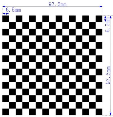
The proposed automatic camera calibration method was compared with the human-computer interaction in MATLAB calibration toolbox through a camera calibration experiment. Before the experiment, a 97.5cm×97.5cm checkerboard (Figure 10) was printed with 15×15 square grids. The checkboard is 1mm in thickness.
Figure 10. The experimental checkerboard
Next, the checkerboard was placed on a horizontal plane and imaged in the camera’s field of view. The camera image has a fixed relative posture. During the imaging process, the sampling parameters were set as follows: the sampling frequency is 0.05 sheets per second, the image size is 2,592 pixels by 1,944 pixels, the image is an 8-bit grayscale image, the checkerboard moving frequency is 0.05 times per second in the camera’s field of view. The checkerboard images were acquired at different postures. Some of these images are displayed in Figure 11 below.
Figure 11. Some checkerboard images
The folder containing the above images was loaded into our calibration program to calibrate the camera parameters. Then, the same images were used to calibrate the camera parameters by the human-machine interaction in MATLAB calibration toolbox. The results of the two calibration approaches were compared through analysis.
4.2. Results and error of the two methods
The internal and external parameters of the camera calibrated by our method are listed in Table 1 below.
Table 1. Results of our calibration method
|
Parameters |
Calibration results |
|
|
Internal parameters |
focal length(fc) |
[1684.953 1679.261]+[143.365 139.698] |
|
Coordinates of the main point (CC) |
[611.654, 577.265]+[4.592, 27.564] |
|
|
Distortion parameters (kc1,kc2,kc3,kc4,kc5) |
[-0.078 0.162 -0.003 -0.001 0]+[0.014 0.066 0.001 0 0] |
|
|
Pixel error (err) |
[0.196 0.265] |
|
|
External parameters (Relative to image I) |
Translation matrix |
[-459.522 -414.535 1656.251 ] |
|
Rotate vector |
[-2.126 -2.212 -0.103] |
|
|
Rotation matrix |
[-0.039 0.999 -0.005; 0.994 0.039 0.097; 0.097 -0.001 -0.995] |
|
|
error |
[0.212 0.260] |
|
Table 2. Results of the human-machine interaction in MATLAB calibration toolbox
|
Parameters |
Calibration results |
|
|
Internal parameters |
focal length (fc) |
[1684.311 1680.742]+[142.106 140.154] |
|
Coordinates of the main point (CC) |
[611.127 577.211]+[4.639 27.131] |
|
|
Distortion parameters (kc1, kc2, kc3, kc4, kc5) |
[-0.081 0.171 -0.003 -0.001 0]+[0.015 0.062 0 0 0] |
|
|
Pixel error (err) |
[0.201 0.271] |
|
|
External parameters (Relative to the first picture) |
Translation matrix |
[-459.522 -414.535 1656.251 ] |
|
Rotate vector |
[-2.119 -2.202 -0.112] |
|
|
Rotation matrix |
[-0.041 0.984 -0.005; 0.989 0.040 0.096; 0.098 -0.001 -0.989] |
|
|
error |
[ 0.236 0.274] |
|
The parameters of the MATLAB calibration tool box were configured according to the operation manual. One of the sample images was selected to identify all the corners in it. Then, the inner-corners were recognized by box selection. These steps were repeated until all images were processed. The internal and external parameters of the camera calibrated by this method are listed in Table 2 below.
4.3. Results analysis
It takes 400 seconds to sample 20 images for calibration. These images could be calibrated by our algorithm in 20 seconds. Thus, the entire calibration process of our algorithm lasts 420 seconds and does not require a professional operator. By contrast, the contrastive method needs to treat and save each image one by one. This method needs 60 seconds to select the inner-corner areas and complete the manual operation, and takes 20 seconds to process one image. Thus, the calibration of 20 images by this method lasts 1,620 seconds and requires a professional operator.
Comparing Tables 1 and 2, it is clear that the two calibration methods achieved roughly the same results, and both controlled the error within ± 0.3 pixel. The slight difference is attributable to the different ways to extract inner-corners of the two algorithms.
This paper presents an accurate and efficient way to automatically calibrate camera parameters based on checkerboard images. The proposed method can extract checkerboard corners without manual intervention, despite the poor quality of checkerboard images. The method also supports the matching between inner-corner points of the checkerboard in the image coordinate system and those in the checkerboard coordinate system when checkerboard is in any state of space. These advantages ensure that the calibrated camera can work satisfactoriness for a broader spectrum of measurement tasks. In addition, the calibration process of our method is robust and accurate (error< ± 0.3 pixel), eliminating the need for manual intervention, and consumes 75% less time than the existing method. No false positive points are observed during the application. The future research will introduce the circular calibration plate to this calibration technique.
Fund project: National Natural Science Foundation of Guangdong Province (2016A030310309), Guangdong Province Science and Technology Project (2017A010102009, 2017B010118004),Guangzhou City Science and Technology Project (201804010354,201707010187), Guangdong Applied Science and Technology Research and Development Special Fund Project (2016B020243012),Innovation and Entrepreneurship Education Project in Colleges and Universities in Guangzhou (201709P09).Guangdong Provincial Department of Transportation Science and Technology Project(Technology-2017-02-025).
Baataoui A., Akkad E. N., Saaidi A. (2016). Robust method for camera self-calibration by an unknown planar scene. Instytut Podstaw Informatyki Polskiej Akademii Nauk.
Bushnevskiy A., Sorgi L., Rosenhahn B. (2016). Multimode camera calibration. IEEE International Conference on Image Processing. IEEE, pp. 1165-1169. https://doi.org/10.1109/ICIP.2016.7532541
Engel J., Koltun V., Cremers D. (2016). Direct sparse odometry. IEEE Transactions on Pattern Analysis & Machine Intelligence, No. 99, pp. 1-1.
Geiger A., Moosmann F., Ömer C. (2012). Automatic camera and range sensor calibration using a single shot. IEEE International Conference on Robotics and Automation. IEEE, pp. 3936-3943. https://doi.org/10.1109/ICRA.2012.6224570
Hai L. I., Zhang X. M., Chen Z. (2015). Automatic corner detection of checkerboard based on LSD. Optics & Precision Engineering, Vol. 23, No. 12, pp. 3480-3489. https://doi.org/10.3788/OPE.20152312.3480
Harris C. (1988). A combined corner and edge detector. Proc. of Fourth Alvey Vision Conference. pp. 147-151.
Hou Z., Wang J. (2012). Study on traditional camera calibration. International Journal on Information, Vol. 15, No. 11, pp. 4393-4398.
Huang F. S., Liu S. G., Peng K. (2006). Self-calibration and simulation of the structure parameters in a light-pen vision measurement system. Journal of Optoelectronics Laser, Vol. 17, No. 6, pp. 705-708.
Jin J., Li X. (2013). Efficient camera self-calibration method based on the absolute dual quadric. Journal of the Optical Society of America A Optics Image Science & Vision, Vol. 30, No. 3, pp. 287-92.
Krüger L., Wöhler C. (2011). Accurate chequerboard corner localisation for camera calibration. Pattern Recognition Letters, Vol. 32, No. 10, pp. 1428-1435.
Leal-Taixé L., Pons-Moll G., Rosenhahn B. (2012). Branch-and-price global optimization for multi-view multi-target tracking. IEEE Conference on Computer Vision and Pattern Recognition. IEEE Computer Society, pp. 1987-1994. https://doi.org/10.1109/CVPR.2012.6247901
Liu Z., Shang Y. (2013). Novel calibration method for stereo vision sensor using flexible target. Acta Optica Sinica, Vol. 33, No. 3, pp. 0315001. https://doi.org/10.3788/AOS201333.0315001
Shan B., Yuan W., Liu Y. (2016). A calibration method for stereovision system based on solid circle target. Acta Optica Sinica, Vol. 36, No. 9, pp. 0915001. https://doi.org/10.3788/AOS201636.0915001
Smith S. M., Brady J. M. (1997). A new approach to low level image processing tech. International Journal of Computer Vision, Vol. 23, No. 1, pp. 45-78. https://doi.org/10.1023/a:1007963824710
Wei G. Q., Ma S. D. (1991). Two plane camera calibration: a unified model. Computer Vision and Pattern Recognition, 1991. Proceedings CVPR '91. IEEE Computer Society Conference on. IEEE, pp. 133-138. https://doi.org/10.1109/CVPR.1991.139675
Yang X., Huang Y., Li Y. (2010). Sub-pixel corner detection algorithm of chessboard image based on improved SUSAN operator. China Mechanical Engineering, Vol. 21, No. 21, pp. 2541-2545.
Zhang A. Y. (2014). Fast approach to checkerboard corner detection for calibration. Optical Engineering, Vol. 53, No. CCC, pp. 112203. https://doi.org/10.1117/1.OE.53.11.112203
Zhang Z. (2000). A flexible new technique for camera calibration. IEEE Computer Society, Vol. 22, No. 11, pp. 1330-1334. https://doi.org/10.1109/34.888718