Dinglong He![]() | Zhonghui Wei*
| Zhonghui Wei*![]()
© 2024 The authors. This article is published by IIETA and is licensed under the CC BY 4.0 license (http://creativecommons.org/licenses/by/4.0/).
OPEN ACCESS
When star sensors operate under near-Earth daytime conditions, the intense background radiation from the sky severely interferes with the energy of the star points in the imagery, resulting in a low signal-to-noise ratio (SNR) for the star points. This low SNR hinders target extraction and centroid positioning, thereby affecting the normal attitude measurement of star sensors. Addressing the challenge of attitude measurement under daytime conditions, this study first analyzes the mapping relationship of pixel positions in consecutive frames of star sensor imagery. A star image superposition algorithm based on attitude-related frames is proposed. On this foundation, an attitude measurement method based on star image superposition is employed for measuring the attitude of daytime star sensors. Furthermore, a fitting algorithm for the solar centroid is introduced, and a coarse measurement method based on solar position is applied to determine the optical axis orientation of daytime star sensors, enhancing their robustness in daylight conditions. The algorithm proposed in this study is validated through experiments. The results demonstrate that the multimodal attitude measurement method not only effectively improves the SNR of near-Earth daytime star sensor imagery through star image superposition, ensuring the accuracy of attitude measurements, but also ensures the robustness of attitude measurements through solar centroid fitting.
near-Earth, daytime star sensors, attitude measurement, star image superposition, centroid positioning
Star sensors, integrating optical systems, mechanical structures, and electronic systems, serve as attitude measurement devices [1]. When operating under near-Earth daytime conditions, these sensors face significant interference from strong background sky radiation, which severely affects the energy of star points [2]. This interference results in a low SNR of star points within the imagery, hindering target extraction and centroid positioning [3], and thereby impacting the normal functioning of star sensors. Ensuring that star sensors can perform accurate attitude measurements under the intense background radiation of daytime skies poses a major challenge and is a primary factor limiting their application in near-Earth daytime conditions [4].
The radiation energy of the night sky background is generally around 10-3cd/m2, whereas the daytime sky background radiation can range from 1×10³cd/m2 ~ 6×10³cd/m2, which is 106 times higher than at night [5]. Such intense background radiation during the day severely interferes with the energy of star points, leading to a low SNR in the imagery. This low SNR prevents effective target extraction and centroid positioning, thus affecting the attitude measurements of the star sensors [6]. From this analysis, it is clear that reducing or eliminating the impact of daytime sky background radiation on the energy of star points, and thereby increasing the SNR of star points, is crucial for enabling normal attitude measurements by star sensors during the day. Therefore, enhancing the SNR of star points is identified as the core issue for achieving daytime attitude measurement with star sensors. Currently, in the field of star sensor research [7], methods to improve the SNR of star points primarily include the following categories:
(a) Spectral filtering method
Daytime sky background radiation is predominantly short-wavelength, with peak energy occurring between wavelengths of 450 to 550 nm. A sharp decline in radiation energy is observed as the wavelength increases, becoming negligible when the wavelength exceeds 900 nm [8].
The temperature of a star's surface determines its radiation energy. Generally, stars can be categorized into seven types based on surface temperature variations: O, B, A, F, G, K, and M. Despite differences in surface temperatures among G, K, and M stars, their radiation energy distribution pattern is similar: weaker in the short-wavelength range and stronger in the long-wavelength range, with a peak around 700 nm [9].
Consequently, there is a significant difference in the distribution patterns of radiation energy between G, K, M stars and the daytime sky background. Additionally, it is noted that G, K, and M stars constitute over 90% of all stars, according to statistics. Theoretically, after selecting an optical system with an appropriate wavelength range, spectral filtering technology can be utilized to suppress daytime sky background radiation energy.
However, in practical applications, selecting an optimal wavelength range that both eliminates sky background radiation and preserves stellar radiation energy proves challenging. Once a wavelength range is chosen, it cannot be altered. An inappropriate selection would fail to achieve the desired filtering effect.
(b) Sky background noise filtering methods
Although spectral filtering methods can suppress most of the daytime sky background radiation, the strong irradiance from the sun during the day still results in residual sky background radiation entering the field of view of star sensors and forming background noise in the imagery on the image sensor. This noise continues to interfere with the energy of star points in the images. Therefore, if the sky background noise in the images captured by star sensors could be filtered, an improvement in the SNR of the star points would subsequently be observed [10].
Currently, the background noise filtering algorithms are primarily divided into two categories: spatial domain filtering and frequency domain filtering [11]. Spatial domain filtering algorithms include classical methods, such as threshold filtering, mean filtering, and median filtering, along with various improved algorithms [12]. Frequency domain filtering algorithms mainly comprise low-pass filtering, high-pass filtering, and band-stop filtering, along with various improved algorithms. However, due to the complexity of implementing frequency domain filtering, which involves Fourier transforming the image and then processing noise in the frequency domain, its practical application is challenging.
Despite the wide application of classical and improved algorithms of both spatial and frequency domain filtering in many professional fields, they may not achieve significant results in the application of daytime star sensors. The reason lies in the fact that when the background noise in the images of star sensors is strong, star points are almost drowned out by the background noise. Without knowing the position and gray values of the star points, using existing background noise filtering algorithms to filter out noise could also damage the energy of the star points, hindering the subsequent extraction of star points for target identification [13].
(c) Enhancement of star point energy
Currently, a commonly utilized method for enhancing the energy of star points is the star image superposition algorithm. The principle of this algorithm is as follows: the star sensor performs multiple exposures, and several frames of exposed star images are superimposed to enhance the SNR of star points within the star image [14]. Despite the reduction in the data update rate of star sensors following the application of the star image superposition algorithm, its low complexity and significant effectiveness have led to widespread application in engineering projects.
However, in practical applications, the star sensor is not stationary during the multiple exposures but is continuously moving due to external factors. Consequently, the positions of star points in adjacent frames are constantly changing. Although the star image superposition algorithm can enhance the SNR of star points to a certain extent, ignoring the changes in star point positions results in a limited improvement in SNR [15].
In response to the limitations of existing methods for enhancing the SNR of star points, this article proposes a multimodal attitude measurement method for daytime star sensors. Firstly, the mapping relationship of pixel positions in consecutive frames of imagery captured by star sensors is analyzed, and a star image superposition algorithm based on attitude-related frames is proposed, improving the SNR of star points within the imagery. On this basis, an attitude measurement method utilizing star image superposition is employed to measure the attitude of daytime star sensors. Furthermore, a fitting algorithm for the solar centroid is introduced, and on this foundation, a coarse measurement method based on the position of the sun is applied to determine the orientation of the optical axis of daytime star sensors, enhancing their robustness in daytime conditions.
As illustrated in Figure 1, once a star is imaged on the target surface of the star sensor's image sensor, the centroid coordinates of the star points can be obtained through target extraction and centroid positioning of the star points in the image. By utilizing the navigation star information from the star catalog to identify the star points in the image, the corresponding navigation stars in the star catalog can be identified. Based on the centroid coordinates of the star points in the image and the navigation star information from the star catalog, the attitude data of the star sensor relative to the inertial coordinate system can be calculated.
Figure 1. Working principle of a star sensor
In Figure 1, ws is the observed vector of the star point in the star sensor coordinate system, and uc is the reference vector of the navigation star in the celestial coordinate system. The relationship between them is as follows:
$w_s=A u_c$ (1)
where, A represents the attitude matrix of the star sensor.
The observed vector of star points in the k-1-th frame of a star image is denoted as $w_s^{k-1}$, with its reference vector being $u_c^{k-1}$. The attitude matrix of the star sensor for this frame is represented by $A_{k-1}$. Similarly, for the $k$-th frame of a star image, the observed vector of star points is denoted as $w_s^k$, with the reference vector being $u_c^k$, and the star sensor's attitude matrix for this frame is $A_k$. Consequently, the observed vectors of a star point in the $k-1$-th and $k$-th frames of the star images can be expressed as:
$\left\{\begin{array}{c}\boldsymbol{w}_s^{k-1}=\frac{1}{\sqrt{x_{k-1}^2+y_{k-1}^2+f^2}}\left[\begin{array}{c}-x_{k-1} \\ -y_{k-1} \\ f\end{array}\right] \\ \boldsymbol{w}_s^k=\frac{1}{\sqrt{x_k^2+y_k^2+f^2}}\left[\begin{array}{c}-x_k \\ -y_k \\ f\end{array}\right]\end{array}\right.$ (2)
In the k-1-th and k-th frames of the star images, the reference vector of the star points remains unchanged, i.e., $u_c^{k-1}=u_c^k$. However, due to the motion of the star sensor, the attitude matrices between these two frames are about to differ, as shown in:
$A_k=T_A A_{k-1}$ (3)
where, TA represents the attitude transition matrix of the star sensor between the k-1-th and k-th frames, which can be defined as:
$\boldsymbol{T}_A=\left[\begin{array}{lll}T_{11} & T_{12} & T_{13} \\ T_{21} & T_{22} & T_{23} \\ T_{31} & T_{32} & T_{33}\end{array}\right]$ (4)
Typically, the inertial navigation system (INS) and the star sensor are rigidly connected on the vehicle [16]. Assuming the installation matrix between the INS and the star sensor is matrix M, the relationship between the attitudes of the INS and the star sensor in the k-1-th and k-th frames of the star images is given by:
$\left\{\begin{array}{l}\boldsymbol{B}_{k-1}=\boldsymbol{A}_{k-1} \boldsymbol{M} \\ \boldsymbol{B}_k=\boldsymbol{A}_k \boldsymbol{M}\end{array}\right.$ (5)
where, Bk-1 and Bk respectively denote the attitude matrices of the INS in the k-1-th and k-th frames of the star images.
For the INS [17], the change in attitude matrices between the k-1-th and k -th star images can be represented by the following equation:
$\boldsymbol{B}_k=\boldsymbol{T}_B \boldsymbol{B}_{k-1}$ (6)
where, TB denotes the attitude transition matrix of the INS between the k-1-th and k-th frames.
Upon organizing Eqs. (5) and (6), it is obtained that AkM=TBAk-1M, which implies Ak=TBAk-1. Comparing this with Eq. (3), it is found that TA=TB, indicating that the attitude transition matrix TA of the star sensor between the k-1-th and k-th frames is identical to that (TB) of the INS [18]. Therefore, in the absence of known attitude transition matrix TA for the star sensor, the attitude data between two frames of star images captured by the INS can be utilized to calculate the attitude transition matrices TB and TA for both the INS and the star sensor.
From Eq. (1), it is understood that the observed vector of star points, the reference vector of the navigation star, and the attitude matrix of the star sensor between the k-1-th and k-th star images satisfy the following relationship:
$\left\{\begin{array}{l}\boldsymbol{w}_s^{k-1}=\boldsymbol{A}_{k-1} \boldsymbol{u}_{\boldsymbol{c}} \\ \boldsymbol{w}_s^k=\boldsymbol{A}_k \boldsymbol{u}_{\boldsymbol{c}}\end{array}\right.$ (7)
Thus, the relationship between the observed vector of star points, the reference vector of the navigation star, and the attitude matrix of the star sensor in the k-th star image can be further expressed as:
$\boldsymbol{w}_s^k=\boldsymbol{A}_k \boldsymbol{u}_{\boldsymbol{c}}=\boldsymbol{T}_A \boldsymbol{A}_{k-1} \boldsymbol{u}_{\boldsymbol{c}}=\boldsymbol{T}_A \boldsymbol{w}_s^{k-1}$ (8)
By combining Eqs. (2) and (8), the following equation is obtained:
$\begin{aligned} & \frac{1}{\sqrt{x_k^2+y_k^2+f^2}}\left[\begin{array}{c}-x_k \\ -y_k \\ f\end{array}\right] \\ & =\frac{1}{\sqrt{x_{k-1}^2+y_{k-1}^2+f^2}}\left[\begin{array}{l}-T_{11} x_{k-1}-T_{12} y_{k-1}+T_{13} f \\ -T_{21} x_{k-1}-T_{22} y_{k-1}+T_{23} f \\ -T_{31} x_{k-1}-T_{32} y_{k-1}+T_{33} f\end{array}\right]\end{aligned}$ (9)
After processing, Eq. (9) can be further expressed as:
$\left\{\begin{array}{l}x_k=f \frac{T_{13} f-T_{11} x_{k-1}-T_{12} y_{k-1}}{T_{31} x_{k-1}+T_{32} y_{k-1}-T_{33} f} \\ y_k=f \frac{T_{23} f-T_{21} x_{k-1}-T_{22} y_{k-1}}{T_{31} x_{k-1}+T_{32} y_{k-1}-T_{33} f}\end{array}\right.$ (10)
Eq. (10) represents the mapping relationship of pixel positions between the k-1-th and k -th frames of star images. Upon acquiring the k -th frame star image, the gray values of pixels (xk-1, yk-1) in the k-1-th frame are superimposed with those of pixels (xk, yk) in the k-th frame according to Eq. (10), thus accomplishing the superposition of star images between the k-1-th and k -th frames.
The SNR is an index that describes the relative magnitude of signal energy to noise energy within an image [19]. In star images, the SNR of star points can effectively assess whether the star points can be accurately extracted. In a star image disturbed by Gaussian noise with a variance of δ, the SNR of a star point with a total signal energy of S is defined as:
$S N R=\frac{S}{\delta}$ (11)
when, n-frame star images affected by Gaussian noise are superimposed, the variance of the superimposed star image becomes:
$\delta^{\prime}=\sqrt{\delta_1^2+\delta_2^2+\cdots+\delta_n^2}=\sqrt{n} \delta$ (12)
The total energy of star points in the superimposed star image is:
$S^{\prime}=n S$ (13)
Using Eqs. (12) and (13), the SNR of star points in the superimposed star image can be calculated to be:
$S N R^{\prime}=\frac{S^{\prime}}{\delta^{\prime}}=\sqrt{n} S N R$ (14)
Based on the calculation results from Eq. (14), it is known that after precisely superimposing the star point energy in n-frame star images using the method described in this section, the SNR of star points in the superimposed star image is improved by a factor of $\sqrt{n}$ compared to before superposition. When an appropriate number n of star image frames is chosen for superposition so that the SNR of star points meets the conditions for star point extraction, the star sensor can perform normal attitude measurements.
When star sensors operate in near-Earth daytime conditions and encounter situations where stars are obscured by clouds, measuring the attitude of the star sensor using star detection methods becomes unfeasible. To address this issue, this section proposes a fitting algorithm for the solar centroid. Based on this, a measurement method reliant on the solar position is employed to coarsely measure the orientation of the optical axis of daytime star sensors, enhancing their robustness in daytime conditions.
3.1 Edge point detection of a solar image
Upon imaging by the star sensor's image sensor, the sun appears as an approximate circle, with all pixels at its edge forming an irregular annulus. To detect the edge points of the solar image, this paper applies the Sobel operator to process the solar image.
Let the grayscale value of all pixels in the 8-neighborhood of a pixel point (x, y) in the solar image be denoted as r(x, y), which can be expressed as:
$r(x, y)=\left[\begin{array}{ccc}f(x-1, y-1) & f(x, y-1) & f(x+1, y-1) \\ f(x-1, y) & f(x, y) & f(x+1, y) \\ f(x-1, y+1) & f(x, y+1) & f(x+1, y+1)\end{array}\right]$ (15)
where, f(x, y) represents the grayscale value at the pixel location (x, y) in the image.
Let the Sobel operator in the x-direction be denoted as Sobelx, and in the y-direction as Sobely, then:
Sobel $_x=\left[\begin{array}{lll}-1 & 0 & 1 \\ -2 & 0 & 2 \\ -1 & 0 & 1\end{array}\right]$, Sobel $_y=\left[\begin{array}{ccc}-1 & -2 & -1 \\ 0 & 0 & 0 \\ 1 & 2 & 1\end{array}\right]$ (16)
Firstly, edge detection is conducted on the solar image f(x, y) in the x-direction by applying the Sobel operator Sobelx in the x-direction to perform convolution operations on f(x, y), resulting in a gradient image gx(x, y) of f(x, y) in the x-direction. The process is described as follows:
$g_x(x, y)=$ Sobel $_x \otimes f(x, y)$ (17)
Subsequently, edge detection is performed on the solar image f(x, y) in the y-direction, utilizing the Sobel operator Sobely in the y-direction for convolution operations on f(x, y) to obtain a gradient image gy(x, y) in the y-direction. This process is defined as:
$g_y(x, y)=$ Sobel $_y \otimes f(x, y)$ (18)
The gradient images gx(x, y) and gy(x, y) of f(x, y) in the x-direction and y-direction are then superimposed to produce a gradient image in both the x and y directions, represented by:
$f_{\text {mag }}(x, y)=|g(x)|+|g(y)|$ (19)
Utilizing the gradient image fmag(x, y), the solar image f(x, y) is processed through threshold filtering to obtain the solar edge image. The process involves setting a threshold value thmag for the gradient image fmag(x, y). If the value fmag(x, y) at the point (x, y) in the gradient image is less than the threshold thmag, the grayscale value f(x, y) at the corresponding point (x, y) in the solar image is set to 0; otherwise, the value remains unchanged, as follows:
$f(x, y)=\left\{\begin{array}{cc}0 & f_{\text {mag }}(x, y)<t h_{\text {mag }} \\ f(x, y) & f_{\text {mag }}(x, y)>t h_{\text {mag }}\end{array}\right.$ (20)
Using the method described in this section, all coordinate points of the solar edge image can be obtained. Sections 3.2 and 3.3 discuss the methods for locating the solar centroid under unobscured and obscured conditions, respectively.
3.2 Solar centroid positioning under unobscured conditions
The set of coordinate points of the solar edge image is denoted as {(x0,y0),⋯,(xn,yn)}. The centroid coordinates of the sun can be obtained through interpolation and subdivision positioning based on these coordinate points. Centroid method, thresholded centroid method, squared weighted centroid method, and surface fitting method are commonly utilized interpolation and subdivision positioning methods [20]. Among these, the thresholded centroid method is selected for calculating the solar centroid coordinates in this study due to its low computational complexity, high positioning accuracy, and insensitivity to image noise. The method is described as follows:
Let the coordinate range of the solar edge image coordinate points in the x-direction be x1≤x≤x2, and in the y-direction be y1≤y≤y2. Then, using the thresholded centroid method, the centroid coordinates $\left(\hat{x}_c, \hat{y}_c\right)$ of the sun are calculated as:
$\left\{\begin{array}{l}\hat{x}_c=\frac{\iint_{\Omega} x \cdot(I(x, y)-T) d x d y}{\iint_{\Omega} I(x, y) d x d y}=\frac{\sum_{x=x_1}^{x_2} \sum_{y=y_1}^{y_2} x \cdot(f(x, y)-T)}{\sum_{x=x_1}^{x_2} \sum_{y=y_1}^{y_2} f(x, y)} \\ \hat{y}_c=\frac{\iint_{\Omega} y \cdot(I(x, y)-T) d x d y}{\iint_{\Omega} I(x, y) d x d y}=\frac{\sum_{x=x_1}^{x_2} \sum_{y=y_1}^{y_2} y \cdot(f(x, y)-T)}{\sum_{x=x_1}^{x_2} \sum_{y=y_1}^{y_2} f(x, y)}\end{array}\right.$ (21)
where, T is the threshold, and f(x, y) is the grayscale value at the position (x, y).
3.3 Solar centroid fitting algorithm under obscured conditions
Typically, after obtaining solar images, star sensors can acquire complete solar edge images through the detection of solar edge image coordinate points. However, when the sun is obscured by clouds, the solar images captured by the star sensors are not clear, and the detection of solar edge image coordinate points may result in incomplete solar edge images. Directly calculating the solar centroid coordinates using these incomplete coordinate points can lead to significant positioning errors. To address this situation, this section proposes a fitting algorithm for the solar centroid under obscured conditions.
Let the coordinates obtained through solar edge image coordinate point detection under obscured conditions be denoted as $\left\{\left(x_0^{\prime}, y_0^{\prime}\right), \cdots,\left(x_n^{\prime}, y_n^{\prime}\right)\right\}$. A loss function is established as follows:
$J=\sum\left(\left(x_i^{\prime}-\hat{x}_c\right)^2+\left(y_i^{\prime}-\hat{y}_c\right)^2-R^2\right)^2$ (22)
where, $\left(x_i^{\prime}, y_i^{\prime}\right)$ represents the solar edge image coordinate points, and $\left(\hat{x}_c, \hat{y}_c\right)$ and $R$ respectively denote the centroid coordinates and radius of the sun in the image.
The least squares method is used to fit the solar centroid $\left(\hat{x}_c, \hat{y}_c\right)$, minimizing the loss function $J$. The process is detailed as follows:
Let $h\left(\hat{x}_c, \hat{y}_c, R\right)=\left(x_i^{\prime}-\hat{x}_c\right)^2+\left(y_i^{\prime}-\hat{y}_c\right)^2-R^2$, then $J=$ $\sum\left(h\left(\hat{x}_c, \hat{y}_c, R\right)\right)^2$. When the loss function $J$ is minimized, the following conditions should be satisfied:
$\left\{\begin{array}{l}\frac{\partial J}{\partial \hat{x}_c}=-4 \times \sum x_i^{\prime} h\left(\hat{x}_c, \hat{y}_c, R\right)=0 \\ \frac{\partial J}{\partial \hat{y}_c}=-4 \times \sum y_i^{\prime} h\left(\hat{x}_c, \hat{y}_c, R\right)=0\end{array}\right.$ (23)
Simplifying Eq. (23) yields the following set of equations:
$\left\{\begin{array}{l}\sum\left(x_i^{\prime 3}-2 x_i^{\prime 2} \hat{x}_c+x_i^{\prime} y_i^{\prime 2}-2 x_i^{\prime} y_i^{\prime} \hat{y}_c\right)=0 \\ \sum\left(y_i^{\prime 3}-2 y_i^{\prime 2} \hat{y}_c+x_i^{\prime 2} y_i^{\prime}-2 x_i^{\prime} y_i^{\prime} \hat{x}_c\right)=0\end{array}\right.$ (24)
Solving the set of equations in Eq. (24) provides the fitted results for the solar centroid coordinates:
$\left\{\begin{array}{l}\hat{x}_c=\frac{S_{x x y} S_{x y}-S_{x x x} S_{y y}-S_{x y y} S_{y y}+S_{x y} S_{y y y}}{2\left(S_{x y}^2-S_{x x} S_{y y}\right)} \\ \hat{y}_c=\frac{-S_{x x} S_{x x y}+S_{x x x} S_{x y}+S_{x y} S_{x y y}-S_{x x} S_{y y y}}{2\left(S_{x y}^2-S_{x x} S_{y y}\right)}\end{array}\right.$ (25)
where, $\begin{aligned} S_{x x x}=\sum x_i^{\prime 3}, S_{x x}=\sum x_i^{\prime 2}, S_{y y y}=\sum y_i^{\prime 3}, S_{y y}=\sum y_i^{\prime 2}, S_{x y}=\sum x_i^{\prime} y_i^{\prime}, S_{x x y}=\sum x_i^{\prime 2} y_i^{\prime}, \text { and } S_{x y y}=\sum x_i^{\prime} y_i^{\prime 2} .\end{aligned}$
3.4 Attitude measurement method based on solar position
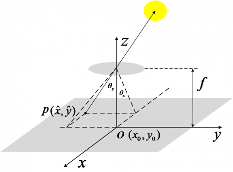
The attitude measurement model based on the solar position is illustrated in Figure 2, where the centroid coordinates $p\left(\hat{x}_c, \hat{y}_c\right)$ of the sun within the solar edge image represent the imaging location of the sun's center on the image sensor target surface of the star sensor.
With the principal point O(x0,y0) and focal length f of the imaging system known, the deviation of the star sensor's orientation relative to the position of the sun can be calculated. The calculation method is as follows:
$\left\{\begin{array}{l}\theta_x=\arctan \frac{\sqrt{\left(\hat{x}-x_0\right)^2}}{f} \\ \theta_y=\arctan \frac{\sqrt{\left(\hat{y}-y_0\right)^2}}{f}\end{array}\right.$ (26)
Since the position and motion pattern of the sun are known in astronomical navigation, upon obtaining the deviation of the star sensor's orientation relative to the sun's position, the optical axis orientation of the star sensor can be determined through angle transformation [21].
Figure 2. Attitude measuring model based on solar location
Images obtained from the star sensor, as specified in Table 1, were utilized to validate the algorithms proposed in this article through simulation experiments.
Table 1. Main technical parameters of the star sensor
|
No. |
Main Technical Parameters |
Value |
|
1 |
Field of view |
8º×8º |
|
2 |
Focal length |
95mm |
|
3 |
Image sensor |
2048×2048(CMOS) |
4.1 Experiment on the star image superposition algorithm based on attitude-related frames
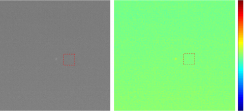
This section validates the proposed star image superposition algorithm based on attitude-related frames through a simulation experiment. Under near-Earth daytime conditions, multiple exposures were conducted using the star sensor to obtain multiple frames of star images. A star point image extracted from the first frame of the star image is shown in Figure 3.
Figure 3. Image detected by star sensor in the daytime
Table 2. SNR of star points in the superposed image
|
Number of Frames Superposed |
1 |
2 |
4 |
6 |
8 |
10 |
12 |
14 |
16 |
18 |
|
Reference [14] |
3.47 |
5.02 |
7.17 |
8.57 |
9.96 |
11.28 |
12.29 |
13.38 |
14.27 |
15.03 |
|
Measured SNR |
3.47 |
5.21 |
7.37 |
8.78 |
10.17 |
11.47 |
12.46 |
13.60 |
14.42 |
15.30 |
|
Theoretical SNR |
3.47 |
4.91 |
6.95 |
8.51 |
9.82 |
10.98 |
12.03 |
13.00 |
13.89 |
14.74 |
As observed from Figure 3, under near-Earth daytime conditions, the star image captured by the star sensor contains significant sky background noise. Compared to this, the energy of star points is weaker, resulting in a SNR of star points in the star image being calculated as 3.47. Based on experience, when the SNR of star points in an image exceeds 8.1, such star points can be accurately extracted. Therefore, it is not feasible to extract targets from the star points shown in Figure 3.
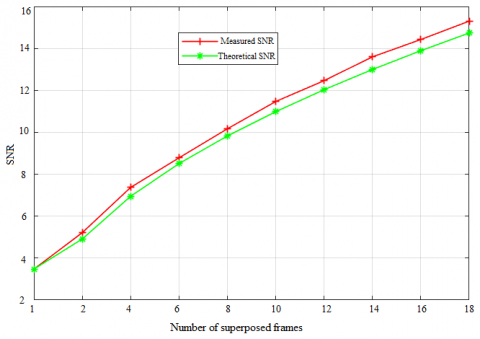
Using the star image superposition algorithm based on attitude-related frames proposed in this study, superposed star images were obtained for different numbers of frames n=2,4,6,8,10,12,14,16,18 as shown in Figure 4, and the SNR of star points in each superposed star image was calculated. Under the same experimental conditions, the algorithm proposed by Yu et al. [14] was used to obtain superposed star images, and the SNR of star points in these superposed images was calculated, as presented in Table 2.
From the experimental results shown in Figure 4 and Table 2, it is observed that as the number of superposed star image frames increases, the energy of star points in the superposed star image gradually intensifies, and the SNR of the star points also progressively increases. Further analysis of the experimental results in Table 2 reveals that under the same number of superposed star image frames, the SNR of star points in the superposed star images processed by the algorithm proposed in this study is higher compared to the algorithm proposed by Yu et al. [14]. The primary reason is that the proposed algorithm maps the pixel positions in adjacent frame star images during the superposition process, concentrating the energy of star points in the superposed images more effectively, thus resulting in a higher SNR for the star points.
Figure 4. Star image after superposition
According to the theoretical analysis in Section 2, the energy of star points in the superposed n-frame star images is expected to increase by n times, as does the energy of the sky background noise by $\sqrt{n}$ times, leading to an increase of $\sqrt{n}$ times in the SNR of star points in the superposed star images. Therefore, to further validate the relationship between the number of superposed star image frames and the SNR of star points in the superposed star images as per the proposed algorithm, data from Table 2 were used to establish the relationship between the measured SNR, theoretical SNR, and the number of superposed star image frames, as illustrated in Figure 5.
Figure 5. Relationship between SNR and the number of superposed frames
From the experimental results depicted in Figure 5, it is observed that as the number of superposed star image frames increases, the growth trend of the measured SNR and the theoretical SNR calculated by the algorithm proposed in this article are essentially consistent. This consistency validates the effectiveness of the proposed algorithm in enhancing the SNR of star points in the n-frame superposed star images by a factor of $\sqrt{n}$.
Based on the simulation experiment results discussed in this section, it can be concluded that when star sensors operate under near-Earth daytime conditions, the star image superposition algorithm based on attitude-related frames proposed in this article effectively improves the SNR of star points in images.
4.2 Experiment on solar centroid fitting
This section validates the proposed solar centroid fitting algorithm through a simulation experiment. Under near-Earth daytime conditions, the star sensor was mounted on a turntable, capturing images of the sun, as shown in Figure 6. Figure 6(a) presents the solar image at time a, where the solar image is very clear. By adjusting the azimuth and elevation angles of the turntable, the imaged sun was kept at a fixed position within the image. Figure 6(b) shows the solar image when obscured by clouds, at which time the solar image is not clear, and the edges of the sun are blurred.
Table 3. Calculation results of solar centroid coordinates
|
Solar Edge Image |
Obscuration Condition of the Sun |
Calculation Method |
Centroid Coordinate x |
Centroid Coordinate y |
|
Figure 7(a) |
Not obscured by clouds |
Thresholded centroid method |
747.14 |
1118.16 |
|
Figure 7(b) |
Obscured by clouds |
Thresholded centroid method |
748.45 |
1117.13 |
|
Figure 7(b) |
Obscured by clouds |
The algorithm proposed in this study |
747.36 |
1118.05 |
Figure 6. Solar images
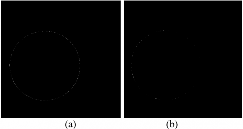
Figure 7. Edges of solar images
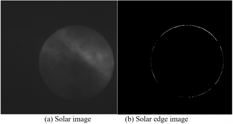
Edge detection was performed on the solar images in Figures 6(a) and 6(b), resulting in the solar edge images shown in Figure 7.
From the experimental results shown in Figure 7, it is observed that when the sun is not obscured by clouds, the integrity of the solar edge image after edge detection is good. However, when the sun is obscured by clouds, the solar edge image after edge detection lacks some edge point information.
The thresholded centroid method was applied to the solar edge images in Figures 7(a) and 7(b) to locate the centroid, obtaining the centroid coordinates of the sun in the images. Additionally, the solar centroid fitting algorithm proposed in this article was used to process the solar edge image in Figure 7(b), fitting the sun's centroid with the edge point information, resulting in an estimated value of the solar centroid coordinates. The experimental results are presented in Table 3.
As shown in Table 3, the solar centroid coordinates calculated from the solar edge image in Figure 7(a) are (747.14,1118.16). Using the thresholded centroid method and the algorithm of this study, the estimated solar centroid coordinates from the solar edge image in Figure 7(b) are (748.45,1117.13) and (747.36,1118.05), respectively. Taking the solar centroid coordinates calculated from the solar edge image in Figure 7(a) as the true value, the experimental results in Table 3 demonstrate that the solar centroid estimated by the algorithm of this article is closer to the true value, with an error within one pixel. Therefore, even under conditions where the sun is obscured by clouds during the day and only incomplete solar edge images are obtained through edge detection, the algorithm proposed in this study still achieves high accuracy in locating the sun's centroid.
Through an outfield star observation experiment, the performance of the algorithm proposed in this article was validated using the star sensor detailed in Table 1. The star sensor was mounted on a three-dimensional precision turntable, and the turntable was rotated to align the optical axis of the star sensor with a specific celestial region. After stabilizing the turntable, imaging was performed with the star sensor, as shown in Figure 8(a). The experimental results from the image indicate that the energy of the star points is weak, and the SNR is low, making it impossible to extract targets. Choosing a star image superposition frame number of 6, the image obtained using the star image superposition algorithm based on attitude-related frames proposed in this article is shown in Figure 8(b). The experimental results from the image demonstrate a significant enhancement in the energy of the star points. After performing target extraction, centroid positioning, and star image identification on the star points in the image, the information of star points and navigation stars obtained is detailed in Table 4. Based on the centroid coordinates of the star points and navigation star information, the attitude angles of the star sensor in yaw, pitch, and roll directions were calculated as 17.1576°, 57.9706°, and 84.9572°, respectively, with an attitude measurement error in the yaw and pitch directions of approximately 30″.
The aforementioned experiment further validates the star image superposition algorithm based on attitude-related frames proposed in this study, proving that the algorithm can effectively address the issue of low SNR of star points in images under daytime conditions, which complicates high-precision attitude measurement by the star sensor.
When the star sensor operates under near-Earth daytime conditions, encountering situations where stars are obscured by clouds can render the star detection method ineffective for measuring the attitude of the star sensor. To address this issue, this article employs a measurement method based on the position of the sun, and the following describes a star observation experiment to verify its performance.
The turntable was rotated to align the optical axis of the star sensor with the sun, and imaging was performed with the star sensor after stabilizing the turntable, as shown in Figure 9(a). At this time, the solar image is not clear, and the edges of the sun are blurred. As shown in Figure 9(b), after performing edge detection on the solar image, the solar edge image reveals missing edge point information when the sun is obscured by clouds.
Figure 8. Star images captured by the star sensor in daytime
Figure 9. Solar image captured by the star sensor in daytime
Table 4. Information on star points
|
Star Point No. |
Centroid Coordinates/Pixel |
Right Ascension/° |
Declination/° |
Magnitude/Mv |
|
1# |
(582.8147, 867.0975) |
12.2750 |
57.8158 |
3.44 |
|
2# |
(684.9058, 162.2785) |
23.4829 |
59.2319 |
4.71 |
|
3# |
(723.1270, 726.5469) |
14.1658 |
59.1811 |
4.63 |
|
4# |
(806.9134, 280.9575) |
21.4541 |
60.2352 |
2.68 |
|
5# |
(903.6324, 698.9649) |
14.1770 |
60.7166 |
2.47 |
The solar centroid fitting algorithm proposed in this study was applied to process the solar edge image in Figure 9(b), using edge point information to fit the sun's centroid. The estimated coordinates (1076.1608,1257.3512) of the solar centroid in the solar edge image were obtained. Given that the principal point of the star sensor is (1023.34,1023.73), the miss distance of the solar centroid position in the image was calculated to be ("52.8208","233.6212"). Consulting the StarMap software revealed the azimuth and elevation angles ("185.2696"°,45.0365°) of the sun at that time. Consequently, based on the miss distance of the solar centroid position, the azimuth and elevation angles of the star sensor were calculated to be (185.0622°,44.8291°), achieving an accuracy of 12' in the star sensor's optical axis orientation.
This experiment further validates the solar centroid fitting algorithm proposed in this study, demonstrating that under daytime conditions when stars are obscured by clouds, it is feasible to conduct a coarse measurement of the star sensor's optical axis orientation using a measurement method based on the sun's position, thus enhancing the robustness of the star sensor's operation in daytime conditions.
Addressing the challenge of high-precision attitude measurement by star sensors under near-Earth daytime conditions, this study has proposed a star image superposition algorithm based on attitude-related frames after analyzing the mapping relationship of pixel positions in consecutive frame images of star sensors. This algorithm improves the SNR of star points in images, and on this foundation, employs a star image superposition-based attitude measurement method to measure the attitude of daytime star sensors. The algorithm has been validated through simulation experiments and near-Earth daytime star observation experiments. Experimental results indicate that as the number of superposed star image frames increases, the energy of star points in the superposed star image gradually strengthens, and the SNR of star points also progressively increases, with the SNR of star points in the superposed star images growing by a factor of $\sqrt{n}$ with the increase in the number (n) of superposed star image frames.
To address the issue of inability to measure the attitude of star sensors by star detection methods under conditions where stars are obscured by clouds during near-Earth daytime, a solar centroid fitting algorithm is proposed. Based on this, a measurement method relying on the sun's position is utilized to coarsely measure the optical axis orientation of daytime star sensors, enhancing their robustness under daytime conditions. The algorithm has been validated through simulation experiments and near-Earth daytime star observation experiments, showing that under conditions where the sun is obscured by clouds during the day, although only incomplete solar edge images are obtained through edge detection, the algorithm proposed in this article still achieves high accuracy in locating the solar centroid, with a positioning error not exceeding one pixel.
In summary, the multimodal attitude measurement method proposed in this study not only effectively enhances the SNR of star sensor images under near-Earth daytime conditions through star image superposition, ensuring the accuracy of attitude measurement but also ensures the robustness of attitude measurement through solar centroid fitting.
[1] Cao, H., Zhan, H., Li, J., Rao, Q., Xing, F., You, Z. (2023). An all-day attitude sensor integrating stars and sun measurement based on extended pixel response of CMOS APS imager. IEEE Transactions on Instrumentation and Measurement, 72: 7003111. https://doi.org/10.1109/TIM.2023.3265092
[2] Liao, Z., Dong, Z., Wang, H., Mao, X., Wang, B., Wu, S., Zang, Y.Z., Lu, Y. (2022). Analysis of flow field aero-optical effects on the imaging by near-earth space all-time short-wave infrared star sensors. IEEE Sensors Journal, 22(15): 15044-15053. https://doi.org/10.1109/JSEN.2022.3187221
[3] Mahi, Z., Karoui, M.S., Keche, M. (2023). A new star detection approach for a satellite-onboard star tracker. Advances in Space Research, 72(6): 2336-2350. https://doi.org/10.1016/j.asr.2023.06.010
[4] Barbot, L., Ferrari, M., Montel, J., Roehlli, Y., Gach, J. L., Thuillot, W., Dohlen, K. (2022). Towards a daytime and low-altitude stellar positioning system: Challenges and first results. In Proceedings of the 2022 International Technical Meeting of The Institute of Navigation, Long Beach, California, pp. 1371-1379. https://doi.org/10.33012/2022.18263
[5] Vasilyuk, N.N., Nefedov, G.A., Sidorova, E.A., Shagimuratova, N.O. (2024). Calibration of the intrinsic parameters of the digital camera of a star tracker based on ground-based observations of stars, taking atmospheric refraction and aberration of light into account. Measurement Techniques, 1-17. https://doi.org/10.1007/s11018-023-02272-z
[6] Jian, D., Teng-fei, S., Yu, L. (2023). A review of daytime atmospheric optical turbulence profile detection technology. Chinese Astronomy and Astrophysics, 47(2): 257-284. https://doi.org/10.1016/j.chinastron.2023.06.001
[7] Zheng, X., Huang, Y., Mao, X., He, F., Ye, Z. (2020). Research status and key technologies of all-day star sensor. Journal of Physics: Conference Series, 1510(1): 012027. https://doi.org/10.1088/1742-6596/1510/1/012027
[8] Clermont, L., Michel, C., Stockman, Y. (2022). Stray light correction algorithm for high performance optical instruments: The case of Metop-3MI. Remote Sensing, 14(6): 1354. https://doi.org/10.3390/rs14061354
[9] Wang, B., Wang, H., Yan, Z., Liu, X., Kang, W., Ning, Q. (2021). A daytime sky analytical model of the degree of polarization for JHKs bands. Infrared Physics & Technology, 119: 103960. https://doi.org/10.1016/j.infrared.2021.103960
[10] Xu, Q., Zhao, C., Li, X. (2021). A strong background daytime star image processing method using improved morphology Top-Hat filter and pipeline filter. In Twelfth International Conference on Graphics and Image Processing (ICGIP 2020), pp. 517-527. https://doi.org/10.1117/12.2589443
[11] Xie, M., Zhang, Z., Zheng, W., Li, Y., Cao, K. (2020). Multi-frame star image denoising algorithm based on deep reinforcement learning and mixed poisson–Gaussian likelihood. Sensors, 20(21): 5983. https://doi.org/10.3390/s20215983
[12] Yugander, P., Tejaswini, C. H., Meenakshi, J., Varma, B. S., Jagannath, M. (2020). MR image enhancement using adaptive weighted mean filtering and homomorphic filtering. Procedia Computer Science, 167: 677-685. https://doi.org/10.1016/j.procs.2020.03.334
[13] Lu, K., Li, H., Lin, L., Zhao, R., Liu, E., Zhao, R. (2023,). A fast star-detection algorithm under stray-light interference. In Photonics, 10(8): 889. https://doi.org/10.3390/photonics10080889
[14] Yu, W., Qu, H., Zhang, Y. (2023). A high-accuracy star centroid extraction method based on kalman filter for multi-exposure imaging star sensors. Sensors, 23(18): 7823. https://doi.org/10.3390/s23187823
[15] Ni, Y., Wang, X., Dai, D., Tan, W., Qin, S. (2023). Limitations of daytime star tracker detection based on attitude-correlated frames adding. IEEE Sensors Journal, 23(22): 27450-27457. https://doi.org/10.1109/JSEN.2023.3317185
[16] Vasilyuk, N.N. (2024). Subpixel stacking and detection of blurred star images observed by an astroinertial attitude sensor against the background of the daytime sky. Computer Optics, 48(2): 303-311. https://doi.org/10.18287/2412-6179-CO-1309
[17] Vasilyuk, N.N. (2023). Correction of rotational blur in images of stars observed by an astroinertial attitude sensor against the background of the daytime sky. Computer Optics, 47(1): 79-91. https://doi.org/10.18287/2412-6179-CO-1141
[18] Vasilyuk, N.N. (2023). Accumulation of motion-blurred star images obtained by a strapdown astroinertial navigation system under daytime conditions. In 2023 30th Saint Petersburg International Conference on Integrated Navigation Systems (ICINS), Saint Petersburg, Russian Federation, pp. 1-5. https://doi.org/10.23919/ICINS51816.2023.10168426
[19] Liu, S., Zhang, J., Sun, G., Zhang, G., Chen, S., Chen, J. (2023). Research on evaluation index of stray light suppression ability of star sensor based on signal-to-noise ratio. Optics Communications, 530: 129175. https://doi.org/10.1016/j.optcom.2022.129175
[20] Zapevalin, P.R., Novoselov, A., Zharov, V.E. (2023). Artificial neural network for star tracker centroid computation. Advances in Space Research, 71(9): 3917-3925. https://doi.org/10.1016/j.asr.2022.11.023
[21] Izadmehr, M., Ghomi, M.K. (2020). An accuracy of better than 200 m in positioning using a portable star tracker. New Astronomy, 74: 101272. https://doi.org/10.1016/j.newast.2019.04.004