Paresh Chandra Sau*![]() | Purnima K. Sharma
| Purnima K. Sharma![]() | Tammireddy J V S Rao
| Tammireddy J V S Rao![]() | Emandi Kusuma Kumari
| Emandi Kusuma Kumari![]() | Thota V N L Aswini
| Thota V N L Aswini![]() | Shilpa Jindal
| Shilpa Jindal![]() | Dinesh Sharma
| Dinesh Sharma![]()
© 2023 IIETA. This article is published by IIETA and is licensed under the CC BY 4.0 license (http://creativecommons.org/licenses/by/4.0/).
OPEN ACCESS
The design of multiband antenna plays a vital role and enhances the functionality of mobile equipment for various wireless services over the last decade. This paper presents a sophisticated quad-band fractal microstrip patch circular monopole antenna with a star shaped slot. The proposed structure is iterated two times to have a Kagome crest fractal antenna. In the paper, optimization of quad band antenna using the Quasi newton Optimizer (QNO) is also presented. Optimizing various design parameters for the proposed antenna in HFSS is simulated. The antenna dimensions are 100mmx100mmx1.6mm occupying an area of 100cm2. Model simulation and experimental validation is done for three frequency ranges, 2.8-3.5GHz, 4.8-7.5GHz and 8.1-9.4GHz, resonating at 3.1GHz, 5.2GHz, 6.8GHz and 8.7GHz respectively. The proposed antenna operates for several wireless applications including RF Energy harvesting, dedicated short range communication, Satellite communication, wireless power transfer to a micro aerial vehicle, etc. can be covered with these band of frequencies. VSWR, return loss, radiation pattern, gain is some of the parameters considered to prove the performance of the fabricated design prototype.
microstrip patch antenna, return loss, RF energy harvesting, fractal, QNO, optimization, Kagome crest
The rapid increase of wireless services and applications, antenna designers are very much interested in combining different wireless communication protocols into a single device. Moreover, multiband antennas are extensively used in smart portable devices, mobile communications, WLAN, WiMAX operate with multiple bands of frequencies. In general, WLAN operates with 2.4, 5.2, 5.4, and 5.8 GHz and 3.3-3.8 GHz for WiMAX. Printed technology proved at its best place in designing the antennas providing reduction in hardware complexity with better performance. The fabrication of these antennas is very simple with compact size. These antennas are made up of a solid dielectric substrate with a conducting material (thin sheet of metal) produced on both sides. Patch refers to the metallic sheet placed on top of the substrate which is connected with the ground plane via a feed network [1]. Patch is the radiating part of antenna and ground plane provides increased bandwidth [2]. The performance of antenna can be enhanced with increase in thickness of the substrate or by decreasing its dielectric constant. Some of the advantages of these antennas are smaller size, low weight, cost effective, easy to integrate on the substrate etc. whereas the limitations include low gain, low efficiency, low power handling capacity [3, 4]. To overcome these limitations, Fractal antenna geometry can be used. The primary benefit of fractal antennas is multiband application with higher gain and reduced size [5-8]. The use of fractals also helps in the improvement of antenna features.
Various multiple-band antennas are proposed for RF energy harvesting using CPW, microstrip line and coaxial feeding techniques [9-12]. Table 1 compares the proposed antenna's size, operational bands, and average peak gain to antennas mentioned in the literature [13-22]. The proposed quad band antenna is proven to be effective at 2.8-3.5GHz, 4.8-7.5GHz and 8.1-9.4GHz frequency bands resonating at 3.1GHz, 5.2GHz and 6.8GHz and 8.7GHz respectively. The most attractive application for the designed antenna can be seen at RF energy harvesting and short range communication. These multiband antennas are also used in MIMO and OFDM [23, 24].
The gain of these antenna should be precisely large so that the reduction in power requirements would ultimately increase the battery life. This can be achieved by using optimization techniques. Basically, they are classified into two types: evolutionary and gradient based algorithms to update the antenna design parameters. Some of the evolutionary algorithms include Genetic algorithm, Simulated annealing, PSO (Particle Swam Optimization) which optimize the antenna using natural or collective behavior of the variables. They are not frequently used as they are inefficient with the increase of design variables [25-29]. However, gradient based algorithms such as Quasi Newton Optimizer can handle for large no. of design variables. They converge fast to the local optima with low computational cost. Solving the objective function is a little complex, hence can be computed using first order methods. In the paper, QNO based optimization is performed and analyzed in the next sections.
Table 1. Comparison of different parameters for various applications
|
Ref |
Size (mm3) & Area(cm2) |
Substrate Material & Its Dielectric Constant |
Feed Type |
Bandwidth/ Frequency Range |
Application |
|
[13] |
20.1x16.6x1.58 &3.3366cm2 |
RT duroid 5880,2.2 |
Inset feed |
5.8-5.95 GHz |
DSRC |
|
[14] |
37x40x1.6 &14.8 cm2 |
Neltec NX9240,2.4 |
Coaxial feed line |
2.39-2.43 GHz |
RF Energy Harvesting |
|
[15] |
53.038x46.676x1.6 & 4.576cm2 |
FR4 Epoxy, 4.4 |
MS line feed with inset feed |
60 & 200 MHz at 2.45 GHz & 5.8GHz |
RF Energy Harvesting |
|
[16] |
23.2x31x1.6 &7.192 cm2 |
FR4 Epoxy, 4.4 |
MS feed line |
5.69-5.89 GHz |
Wireless power transfer to a MAV |
|
[17] |
100x100x1.6 &100 cm2 |
FR4 Epoxy, 4.4 |
CPW |
0.88-8.45 GHz |
RF Energy Harvesting |
|
[18] |
25x40x1.6 |
FR4 Epoxy, 4.4 |
MS line feed |
2.27 GHz–2.6GHz and 3.0 GHz-20 GHz |
WLAN/ WiMAX and UWB |
|
[19] |
70x70x1.6 & 49 cm2 |
FR4 Epoxy, 4.4 |
Inset feed |
2.35 & 3.7 GHz |
RF Energy Harvesting |
|
[20] |
205x275x1.6 &563.75 cm2 |
3 layers: FR4-air-FR4,4.4 |
MS line feed |
1.526-1.626 GHz |
RF Energy Harvesting |
|
[21] |
28x28x1.6 &5.76 cm2 |
FR4 Epoxy, 4.4 |
Co-axial probe feed |
3.3, 4.7 and 6.7GHz |
Wi-Max |
|
[22] |
123.39x83.6x1.6 & 103.154cm2 |
FR4 Epoxy, 4.4 |
MS line feed with inset feed |
6.85-7.15 GHz |
Satellite Communication |
The proposed antenna design and geometrical structure of various iterations of the antenna are discussed here. The Kagome crest is a star shaped design. It is generally viewed as a six coned star or as an eight coned star. The iterations are based on the fractal design keeping all the other parameters same such as substrate height, material and feeding technique. The performance of the antenna largely depends upon its geometrical parameters and dielectric constant of substrate. The recommended antenna uses the substrate of FR4 epoxy having dielectric constant of 4.4.
The substrate has 0.02 dielectric loss tangents with 1.6 mm thickness. Also, the type of feeding used and the feeding point are important parameters to decide the overall performance of antenna. Feed used in the design is provided with 50-ohm microstrip transmission line. The antenna size considered is 100mm x 100mm x 1.6mm along with the ground plane.
The 0th- iteration of the proposed antenna is depicted in Figure 1 (a), in which there is a circular patch with star pattern is slotted on it [19]. To be precise, there are 2 concentric equilateral triangles of same size and opposite direction that are slotted from the circular patch.
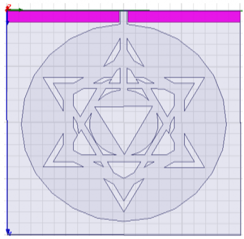
The first iteration of the antenna is obtained as shown in Figure 1 (b), where the notch (rectangular strip connected to the feed) is expanded and connected to another star shaped strip in which a circle is added in the middle and a small equilateral triangle is slotted from that circle. It is to be noted that all the triangles and circle are concentric. To obtain the second iteration proposed antenna, a hexagonal strip is added [28]. The dimensions are given along with the geometrical structure in Figure 1(c). Thus, the Kagome crest fractal antenna is designed which exhibits better radiation and gain. Figure 2 clearly depicts the bottom view (ground plane) of the design for all iterations.
Figure 1. Geometrical structure of the antenna: (a) 0-iteration, (b) 1-iteration, (c) 2-iteration
Figure 2. Bottom view of the proposed antenna with ground plane
Figure 3. Fabricated proposed antenna (a) Kagome crest star shaped patch for radiation (b) Ground substrate
The radius of the circle in the middle is updated using an optimization method. Quasi Newton optimizer (QNO) is one of the gradient based algorithms [29]. The objective function is optimized to the local minima. It finds the updated variables of the given function. The objective function is related to the design parameters of the antenna including thickness, radius, power or force, etc. The QNO is used to find the zeros or local maxima or minima values of the design variables using first order method. This has the advantage of antenna having large number of variables to optimize the design. The function is Hessian matrix which is asymmetric matrix calculated by a quadratic method and solved for zeros. This matrix is updated by computing successive gradients of the variables. In the optimization process, the gradients and Hessian are calculated as
$\nabla g\left(x_k+\Delta x\right)=\nabla g\left(x_k\right)+H \Delta x$ (1)
where, $\nabla g$ is the gradient and H is the Hessian matrix. The unknown variable $x_k$ is updated using the current approximate Hessian matrix at each iteration. Thus, the optimization is done by varying the radius of the circle from 41mm to 42.51mm. Figure 3 shows the fabricated antenna after optimization.
The proposed antenna's properties, such as return loss, VSWR, radiation pattern, and gain, are defined and performance at various iterations are discussed in this section. An antenna's return loss is a percentage of the total amount of power transmitted to the antenna. The lower the return loss, the more power transmitted, and the more efficient the antenna can be. For microstrip antennas, return loss must be less than -10dB, which implies that 90% of the available power is delivered to antenna. Figure 4 clearly depicts the return loss for various iterations. The 0th iteration has 4 resonant frequencies at 3.1, 5.2, 6.8 and 8.7GHz respectively, with lowest return loss value of -23.48dB occurring at 5.2 GHz. The 1st iteration has better impedance matching property than the 0th iteration as inferred from the graph. Although, it also has 4 frequency bands around similar frequencies but there is an improvement in return loss which is -38.42dB at 5.3GHz. Hence more power is delivered to the antenna making it more efficient. The 1st iteration has return loss value around -15dB at other 3 resonant frequencies and hence is not much useful at these frequencies. The 2nd iteration, which is the proposed antenna design overcomes this with significant return losses at all the 4 bands. The parameter analysis of resonant frequencies, bandwidth obtained and the simulated return loss at the resonant frequencies for the proposed design is given in Table 2. The proposed antenna's simulated and measured return loss using a network analyzer demonstrated in Figure 5. Manufacturing tolerances, thickness uncertainty, FR4 substrate dielectric constant, and SMA connector quality all contribute to the variance between simulated and measured values.
The impedance matching among the antenna and connected transmission line is signified by VSWR. The VSWR value between 1 and 2 is considered good for patch antenna performance. VSWR values obtained for the optimized antenna are 1.2893, 1.1160, 1.1056 and 1.1250 at resonant frequencies of 3.1GHz, 5.2GHz, 6.8GHz and 8.7GHz respectively. The VSWR is depicted in Figure 6 with different markers showing the value of the VSWR at the resonant frequencies.
Figure 7 demonstrates the strength of radio waves radiated by the antenna in different directions. The proposed optimized antenna measured radiation pattern at four resonant frequencies indicates the efficiency of the antenna for various 5G applications. The optimized quad-band antenna's radiation patterns are predicted with E-plane and H-plane under HFSS environment. Also measured in an anechoic chamber with in-house antenna measuring equipment. The patterns are measured with a reference antenna generally horn antenna. Radiation patterns in the E-plane are bidirectional, but those in the H-plane are omni directional (dumb bell shaped). Furthermore, the measured and simulated results are nearly identical, with slight differences due to measurement and alignment problems.
Figure 4. Performance of the antenna in terms of return loss curves at various iteration
Figure 5. Analysis of simulated and measured return loss of proposed antenna
Figure 6. Simulated VSWR at multiband frequencies of the antenna
Table 2. Parameter analysis of the proposed antenna at multiband frequencies
|
Frequency |
Bandwidth |
Resonant Frequency |
Percentage Bandwidth |
Return Loss |
|
2.8-3.5GHz |
700MHz |
3.1GHz |
22.58% |
-17.96dB |
|
4.8-7.5GHz |
2700MHz |
5.2GHz &6.8GHz |
51.92% &39.7% |
-25.21dB &-26dB |
|
8.1-9.4GHz |
1300MHz |
8.7GHz |
14.94% |
-24.6dB |
Figure 7. Stable radiation patterns of the proposed quad-band antenna at resonating frequencies of a)3.1GHz, b) 5.2GHz, c) 6.8GHz and d) 8.7GHz
The simulated and measured radiation patterns of the proposed quad-band fractal antenna is represented in Figure 7. E-plane and H-plane patterns at different resonating frequencies of 3.1GHz, 5.2GHz, 6.8GHz and 8.7GHz proved the performance antenna. Figure 8 illustrates the antenna's total gain at the four resonant frequencies where it is found to be the highest. The CPW feeding technique is an effective technique achieves wide frequency ranges. The feeder is connected with both sides of the ground plane. At 50-ohm, CPW is found to be more lossy than Microstrip line and the coupling efficiency along with the quality factor (Q) is less. Therefore, impedance bandwidth is more in CPW feed. In this work, microstrip line feed is employed and hence this antenna incurs reduced losses.
Table 3 compares the proposed antenna with [18-22] for substrate type, antenna size, number of frequency bands, bandwidth and return loss. As the optimized antenna achieves highest number of frequency bands are obtained with return loss less than -10dB and hence it can be used for variety of applications such as RF energy harvesting, satellite communication etc. The proposed optimized antenna performance in terms of reflection coefficient is depicted in Figure 9. It was observed that Kagome Crest Fractal antenna has low losses and wide bandwidth when it was optimized with the Quasi newton algorithm. Figure 10 represents the parametric analysis of the proposed antenna with variation in radius of the patch. After optimization, it achieves better performance at 44mm of radius.
Figure 9. Proposed antenna using optimization
Figure 10. Optimization results by varying the patch radius
Table 3. Comparative analysis of different parameters of the proposed antenna
|
Ref |
Type of Substrate |
Size (mm3) |
Frequency Bands (GHz) |
Bandwidth (MHz) |
Return Loss(dB) |
Antenna Purpose |
|
Proposed Antenna |
FR4 Epoxy |
100x100x1.6 |
2.8-3.5 4.8-7.5 8.1-9.4 |
700 2700 1300 |
-17.96 at 3.1 -25.21 at 5.2 -26 at 6.8 -24.6 at 8.7 |
RF Energy harvesting, DSRC, Satellite comm. |
|
[18] |
FR4 Epoxy |
25x40x1.6 |
2.27 GHz–2.6GHz and 3.0 GHz-20 GHz |
7500 |
-18 at 2.4 |
WLAN/WiMAX & UWB |
|
[19] |
FR4 Epoxy |
70x70x1.6 |
2.35 and 3.7 |
- |
-23.23 at 2.35 -21.6 at 3.7 |
RF Energy harvesting |
|
[20] |
FR4-air-FR4 |
205x275x1.6 |
1.526-1.626 |
100 |
-13.449 at 1.575 |
RF Energy harvesting |
|
[21] |
FR4 Epoxy |
28x28x1.6 |
3.3, 4.7 and 6.7 |
- |
-15.68 at 3.3 -17.71 at 4.7 -33.82 at 6.7 |
WiMAX |
|
[22] |
FR4 Epoxy |
123.39x83.6x1.6 |
6.85-7.15 |
300 |
-27.533 at 7 |
Satellite comm. |
In this paper, a novel design of Kagome crest quad band fractal geometry antenna including a star shaped slot is proposed and it is optimized using a gradient based algorithm of Quasi Newton optimizer. Antenna design at various iterations is examined and optimization improved the operational performances of the designed antenna. This antenna is simulated and fabricated prototype was analyzed with the network analyzer. It resonates at quad frequencies of 3.1, 5.2, 6.8 and 8.7GHz. The antenna offers a bandwidth of 51.92% (4.8-7.5GHz) & a peak gain of 7.78dB providing better impedance matching and stable radiation characteristics. The optimized antenna improved the return loss at frequencies 2.8-3.5GHz, 4.8-7.5GHz & at 8.1-9.4GHz. The proposed antenna has multiple bands with high bandwidth was observed with the maximum gain of 7.7896dBi. The simulations and practical measured results proved that the antenna is preferable for WLAN, RF Energy harvesting, mobile and wireless applications.
[1] Sarkar, M., Mishra, S., Daniel, A., Dwari, S. (2019). Design of a variable depth axially corrugated horn antenna at X-band for low cross-polarization applications. Wireless Personal Communications, 108: 269-280. https://doi.org/10.1007/s11277-019-06402-1
[2] Sharma, M. (2020). Design and analysis of multiband antenna for wireless communication. Wireless Personal Communications, 114(2): 1389-1402. https://doi.org/10.1007/s11277-020-07425-9
[3] Gupta, N., Saxena, J., Bhatia, K.S. (2019). Design of wideband flower-shaped microstrip patch antenna for portable applications. Wireless Personal Communications, 109(1): 17-30. https://doi.org/10.1007/s11277-019-06547-z
[4] Kumar, M.V., Sharma, D. (2022). Enhancement of gain and reduction of backward radiation using metasurface antenna for energy harvesting applications. Traitement du Signal, 39(2): 755-762. https://doi.org/10.18280/ts.390241
[5] Desai, A., Upadhyaya, T.K., Patel, R., Bhatt, S., Mankodi, P. (2018). Wideband high gain fractal antenna for wireless applications. Progress In Electromagnetics Research Letters, 74: 125-130.http://dx.doi.org/10.2528/PIERL18011504
[6] Chouhan, S., Panda, D.K., Gupta, M., Singhal, S. (2018). Multiport MIMO antennas with mutual coupling reduction techniques for modern wireless transreceive operations: A review. International Journal of RF and Microwave Computer‐Aided Engineering, 28(2).
[7] Chouhan, S., Panda, D.K., Gupta, M., Singhal, S. (2018). Meander line MIMO antenna for 5.8GHz WLAN application. International Journal of RF and Microwave Computer‐Aided Engineering, 28(4): e21222. https://doi.org/10.1002/mmce.21222
[8] Wang, L., Yu, J., Xie, T., Bi, K. (2021). A novel multiband fractal antenna for wireless application. International Journal of Antennas and Propagation, 2021: 1-9. https://doi.org/10.1155/2021/9926753
[9] Bhatia, S.S., Sivia, J.S. (2016). A novel design of circular monopole antenna for wireless applications. Wireless Personal Communications, 91: 1153-1161. https://doi.org/10.1007/s11277-016-3518-z
[10] Roy, C., Khan, T. (2019). Single-feed dual-polarized high gain microstrip antenna. Wireless Personal Communications, 108(3): 1417-1430. https://doi.org/10.1007/s11277-019-06476
[11] Sharma, S., Kanaujia, B.K., Khandelwal, M.K. (2020). Theoretical analysis and design of high-stable-gain antenna with ultrawide band capabilities and suppressed back radiations. Wireless Personal Communications, 112(1): 1-19. https://doi.org/10.1007/s11277-019-07012-7
[12] Bejan, A. (2016). Constructal thermodynamics. International Journal of Heat and Technology, 34: S1-S8. http://dx.doi.org/10.18280/ijht.34S101
[13] Tiwari, N., Kumar, S. (2014). Microstrip patch antenna for 5.9 GHz dedicated short range communication system. International Journal of Advance Electrical and Electronic Engineering, 3(4): 1-4.
[14] Kaur, S., Kakkar, S., Rani, S. (2018). Design and analysis of microstrip patch antenna for RF energy harvesting. International Journal of Electrical Electronics & Computer Science Engineering, 5(2): 4.
[15] Shrestha, S., Lee, S.R., Choi, D.Y. (2014). A new fractal-based miniaturized dual band patch antenna for RF energy harvesting. International Journal of Antennas and Propagation, 2014. https://doi.org/10.1155/2014/805052
[16] Almorabeti, S., Hanaoui, M., Rifi, M., Terchoune, H. (2017). Microstrip patch antennas at 5.8 GHz for wireless power transfer system to a MAV. In Proceedings of the 2nd International Conference on Computing and Wireless Communication Systems, pp. 1-8. https://doi.org/10.1145/3167486.3167499
[17] Bai, X., Zhang, J.W., Xu, L.J. (2017). A broadband CPW fractal antenna for RF energy harvesting. In 2017 International Applied Computational Electromagnetics Society Symposium (ACES) IEEE, pp. 1-2.
[18] Naidu, P.V., Sharma, D., Kumar, A., Rohini, R., Sharma, P. (2018). Semi Circular Printed Monopole Antenna with ℧ Shaped Slot for UWB Applications. In 2018 Progress in Electromagnetics Research Symposium (PIERS-Toyama), IEEE, pp. 833-837. https://doi.org/10.23919/PIERS.2018.8598201
[19] Sudeep, D.K., Kumaraswamy, H.V. (2019). A dual band microstrip patch antenna for RF energy harvesting. International Journal of Engineering Research and Technology, 8(6). https://doi.org/10.17577/IJERTV8IS060055
[20] Savitri, I., Anwar, R., Amrullah, Y.S., Nurmantris, D.A. (2018). Development of large aperture microstrip antenna for radio wave energy harvesting. Progress In Electromagnetics Research Letters, 74: 137-143. http://dx.doi.org/10.2528/PIERL18030305
[21] Singh, A., Singh, J. (2016). Slotted rectangular microstrip patch antenna for Wi-Max applications. An International Journal of Engineering Sciences, 17: 520-524.
[22] Das, S., Gokhroo, S. (2015). Microstrip patch antenna at 7 GHz for satellite communication. International Journal of Engineering Technology Science and Research IJETSR, 2(11): 9-11.
[23] Agrawal, N., Gupta, M., Chouhan, S. (2022). Modified ground and slotted MIMO antennas for 5G sub-6 GHz frequency bands. International Journal of Microwave and Wireless Technologies, 1-9. https://doi.org/10.1017/S1759078722000770
[24] Chaturvedi, A., Kumar, M., Meena, R.S., Sharma, G.K. (2021). Wideband ring mixer for band﹟1 of MB-OFDM systems in 180 nm CMOS technology. Journal of Electrical Engineering, 72(5): 323-329. https://doi.org/10.2478/jee-2021-0045
[25] Chaturvedi, D., Raghavan, S. (2019). A compact metamaterial-inspired antenna for WBAN application. Wireless Personal Communications, 105: 1449-1460. https://doi.org/10.1007/s11277-019-06153-z
[26] Alami, A., Bennani, S.D., Bekkali, M., Benbassou, A. (2013). Design, analysis and optimization of a microstrip patch antenna at frequency 3.55GHZ for wimax application. Journal of Theoretical and Applied Information Technology, 53(2): 157-162.
[27] Koteswara Rao Devana, V.N., Kusuma Kumari, E., Chakradhar, K.S., Kadali Sharma, P., Rama Devi, D., Manohar Kumar, C., Raj V.D., Prasad, D.R. (2022). A novel foot‐shaped elliptically embedded patch‐ultra wide band antenna with quadruple band notch characteristics verified by characteristic mode analysis. International Journal of Communication Systems, 35(15): e5284. https://doi.org/10.1002/dac.5284
[28] Sowmya, M., Nagaraju, P., Totad, S.B., Rakesh, K.S. (2017). Design and simulation of multiband fractal antenna with various geometries. In 2017 International Conference on Intelligent Computing and Control (I2C2) IEEE, pp. 1-5. https://doi.org/10.1109/I2C2.2017.8321867
[29] Al-Baali, M., Khalfan, H. (2007). An overview of some practical quasi-Newton methods for unconstrained optimization. Sultan Qaboos University Journal for Science (SQUJS), 12(2): 199-209. https://doi.org/10.24200/squjs.vol12iss2pp199-209