Weiming Luo* | Jianhu Sun | Yu Liao | Zhenyu Zhang
© 2022 IIETA. This article is published by IIETA and is licensed under the CC BY 4.0 license (http://creativecommons.org/licenses/by/4.0/).
OPEN ACCESS
Early discovery of civil structure crack facilitates timely treatment, such as repair, reinforcement and grouting. The image processing – based rapid and accurate detection method for civil structure crack brings important research value. In view of complicated construction site of civil project and complex and diversified civil structure, existing method cannot realize crack detection and geometric measurement accurately. Therefore, this article researches the real-time image processing-based detection method for civil structure crack. Bilateral filtering algorithm was used to finish smoothing processing. Crack edge of civil structure was extracted with interpolation calculation – based subpixel edge detection algorithm, to obtain more accurate crack edge position. Civil structure crack was detected based on end-to-end object detection network YOLO. The effectiveness of the model built was verified according to experimental results.
image processing, civil structure crack, crack detection
Hazard of crack is enormous [1-5] for civil projects. The reasons for cracks in civil structure mainly include load, temperature change, poor quality of construction materials and poor construction process quality. The problem breaks the original mechanical structure of civil project, affects durability of civil structure directly and further causes project safety quality problem. Therefore, the earlier the crack of civil structure is discovered, the better it will be, so that we could make repair, reinforcement and grouting timely [6-11]. With rapid development of image processing technology over the past several years, image processing-based crack detection for civil structure became a focus among scholars both at home and broad [12-14]. The research on rapid and accurate civil structure crack detection method has important research value.
A kind of high-calculation efficiency deep learning (DL) model for crack/non-crack real-time classification was discussed in Geetha and Sim [15], where scalable AI (XAI) was used to study “black box” nature of DL model raised. Integrated with image binarization and Fourier-based 1D DL model, the framework is used to detect and classify concrete crack/non-crack characteristics quickly. A weak supervision network to segment and detect asphalt concrete bridge deck crack was developed in Zhu and Song [16]. First, data was distinguished through encoder and unmarked data characteristics were highlighted, so as to make original data generate weakly supervised convergence starting point. Second, characteristics were classified through K-means cluster (KMC). Then, semantic segmentation was implemented against crack in bridge deck defect image under weak supervision. According to experiment results, the method proposed could yield remarkable and better segmentation effect in all six types of defects, in comparison to other methods reported in references. A kind of DL object detection framework was proposed in Zhou et al. [17] by combining texture characteristics and concrete crack data. Texture characteristics and pre-processed concrete data were combined to increase quantity of characteristic channels, so as to lower demand for model training model and improve training speed. With this framework, concrete crack detection can be realized even if there are a limited number of samples available. A kind of analysis method was proposed in Xu et al. [18] to check crack development of glass fiber reinforced polymer (GFRP) - sea sand concrete composite material. The method is exported by analyzing strain dissipation and shear lag behavior and crack can be recognized quantitatively by the proposed Fourier transform analysis model. As shown by result, forecast error is less than 10%.
In view of complicated construction site of civil project and complex and diversified civil structure, existing method cannot realize crack detection and geometric measurement accurately. The main reason lies in the failure to pre-process civil structure crack through image processing technology and to extract crack intersection point steadily. For complicated and diversified civil structure, overfitting or underfitting problem easily occurs once the existing method is used, resulting in the failure to extract effective crack characteristic information. Therefore, this article researches the image processing-based real-time detection method for civil structure. The civil structure crack image was smoothed with bilateral filtering algorithm in Chapter 2 of this article. In Chapter 3, civil structure crack edge was extracted with interpolation calculation – based subpixel edge detection algorithm, so as to obtain more accurate crack edge position. After finishing pre-processing and edge extraction of civil structure crack image, civil structure crack was detected based on end-to-end object detection network YOLO in Chapter 4. The effectiveness of the model built was verified according to experimental results.
In reality, the acquired civil structure crack image contains many noisy points owing to multiple influence factors of light, temperature and acquisition equipment and these noisy points are unfavorable to classification of subsequent images and detection of civil structure crack. Therefore, civil structure crack image should be denoised prior to detection. In this article, bilateral filtering algorithm was used to smooth civil structure crack image.
Bilateral filtering means processing image through two gaussian filters. Suppose the gray information of crack image TX of civil structure in coordinate e=(i, j) is expressed as TXe, image obtained after filtration as TXS, gray value of image after filtration as TXYE, set of pixels in the neighborhood of filtered area as R, normalizing factor as QE and neighborhood pixel as w=(v, u), expression formula of bilateral filtering can be expressed as:
$T X_E^Y=\frac{1}{Q_E} \sum_{w \in R} H_{\rho_c}\left(\left\|\begin{array}{c}e \\ -w\end{array}\right\|\right) H_{\rho_s}\left(\left\|\begin{array}{l}T X_e \\ -T X_w\end{array}\right\|\right) T X_w$ (1)
$Q_E=\sum_{w \in R} H_{\rho_c}(\|e-w\|) H_{\rho_s}\left(\left\|T X_p-T X_w\right\|\right)$ (2)
Suppose the distance standard deviation and gray standard deviation are expressed as ρc and ρs,, spatial proximity factor as Hρc and gray similarity factor as Hρs, the calculation formula can be expressed as:
$H_{\rho_c}(\|e-w\|)=p^{-\left[(a-v)^2+(b-u)^2\right] / 2 \rho_c^2}$ (3)
$H_{\rho_s}\left(\left\|T X_e-T X_w\right\|\right)=p^{-\left[T X_e-T X_w\right] / 2 \rho_s^2}$ (4)
The weighted value of TX pixel of civil structure can be adjusted through two parameters, i.e. relative spatial space and gray variation range, of which, the former is used to control pixel position. Crack image of civil structure can be pre-processed by setting the two parameters.
In actual construction site of civil project, light-sensitive face of image acquisition equipment is easily disturbed by lighting or lights on its own light-sensitive unit. Since response signal of significant object edge in image varies gradually and the part with most significant change in gradual variation can be believed the accurate crack edge of civil structure. In this article, interpolation calculation - based subpixel edge detection algorithm was used to extract the crack edge of civil construction in order to obtain the position of crack edge more accurately.
Suppose the distance among upper photosensitive units at A direction is expressed as q and that among upper photosensitive units at B direction as f, it can be believed that crack detection precision of civil structure is affected by q and f. According to the interpolation calculation - based subpixel edge detection algorithm, the first step is to obtain an integer pixel level edge of civil structure. The second step is to implement interpolation calculation for each edge pixel of civil structure crack to obtain information of its sub-pixel edge. Suppose the interpolation point is expressed as a1 and discrete function value as b1, Formula 5 shows the expression formula of polynomial interpolating function as below:
$g(a)=\sum_{\substack{l=0 \\ m \neq l}}^m \frac{\left(a-a_0\right) \cdots\left(a-a_{m-1}\right)\left(a-a_m\right)}{\left(a_l-a_0\right) \cdots\left(a_l-a_{m-1}\right)\left(a_l-a_m\right)}\quad b_l$ $=\sum_{l=0}^m \prod_{\substack{i=0 \\ i \neq l}}^m \frac{a-a_i}{a_l-a_i} b_l$ (5)
Sobel operator was used to detect and determine the edge point (ai, bj) by taking the three points ai-q, ai and ai+q as interpolation points, so as to further obtain position of sub-pixel edge E. Suppose the gradient function value is expressed as O(i, j), take the three points O(i-1, j), O(i, j) and O(i+1, j) successively in A direction of civil structure crack gradient and put information of various points into above formula, to generate the difference function E(a) in A direction, which can be expressed as:
$E(a)$$=\frac{\left(a-a_i\right)\left[a-\left(a_i+q\right)\right]}{\left[\left(a_i-q\right)-a_i\right]\left[\left(a_i-q\right)-\left(a_i+q\right)\right]} \quad O_{(i-1, j)}$ $+\frac{\left[a-\left(a_i-q\right)\right]\left[a-\left(a_i+q\right)\right]}{\left[a_i-\left(a_i-q\right)\right]\left[a_i-\left(a_i+q\right)\right]} \quad O_{(i, j)}$ $+\frac{\left(a-a_i\right)\left[a-\left(a_i-q\right)\right]}{\left[\left(a_i+q\right)-\left(a_i-q\right)\right]\left[\left(a_i+q\right)-a_i\right\rceil} \quad O_{(i+1, j)}$ (6)
Derive E(a), to make sure d(e(a))/da=0. Suppose the pixel width in A direction is expressed as q and the condition O(i, j)>O(i-1, j), O (i, j)>O(i+1, j) is satisfied, coordinate of sub-pixel A direction in the form of discrete difference can be obtained further through the formula below:
$A=a_i+\frac{O_{(i-1, j)}-O_{(i+1, j)}}{O_{(i-1 . j)}-2 O_{(i, j)}\quad+O_{(i+1, j)}} \times \frac{q}{2}$ (7)
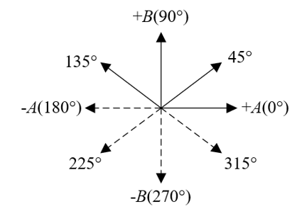
Figure 1. Direction diagram of civil structure crack edge
Similarly, take three points O(i-1, j), O(i, j) and O(i+1, j) in B direction and put them into Formula 5, to obtain the expression formula of interpolation function E(b) in B direction as shown in the formula below:
$E(b)=\frac{\left(b-b_i\right)\left[b-\left(b_i+q\right)\right]}{\left[\left(b_i-q\right)-b_i\right]\left[\left(b_i-q\right)-\left(b_i+q\right)\right]} \quad O_{(i-1, j)}$$+\frac{\left[b-\left(b_i-q\right)\right]\left[b-\left(b_i+q\right)\right]}{\left[b_i-\left(b_i-q\right)\right]\left[b_i-\left(b_i+q\right)\right]} \quad O_{(i, j)}$$+\frac{\left(b-b_i\right)\left[b-\left(b_i-q\right)\right]}{\left[\left(b_i+q\right)-\left(b_i-q\right)\right]\left[\left(b_i+q\right)-b_i\right]} \quad O_{(i+1, j)}$ (8)
Derive E(b), to make sure d(e(b))/db=0. Suppose the pixel in B direction is expressed as f and the condition O(i, j)>O(i-1, j), O (i, j)>O(i+1, j) is satisfied, coordinate of sub-pixel B direction in the form of discrete difference can be obtained further through the formula below:
$B=b_i+\frac{O_{(i-1, j)}\quad-O_{(i+1, j)}}{O_{(i-1 . j)}-2 O_{(i, j)}\quad+O_{(i+1, j)}} \times \frac{f}{2}$ (9)
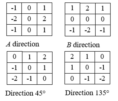
Figure 2. Sobel operator template
Since the sub-pixel position of civil structure crack edge is obtained through derivation and calculation, gradient direction of civil structure crack edge is indefinite. Figure 1 shows the direction diagram of civil structure crack edge. To obtain gradient direction of civil structure crack edge point, Sobel operator was used in this article to roughly extract civil structure crack edge, and gradient direction of known edge pixel was used to approximately substitute gradient direction of unknown sub-pixel. Through interpolation in this direction, accurate sub-pixel position of civil structure crack edge was calculated and obtained. The specific algorithm implementation steps are as below:
STEP1: By combining the four Sobel operator orientation templates (see Figure 2), implement convolution calculation based on pixel-level edge point E0 in civil structure crack image extracted via Sobel operator. Convolution calculation result is expressed as Bi;
STEP2: Take absolute value of Bi. Suppose template in the ith direction is expressed as Oi. 3×3 field of edge point E0 is expressed as E'0, i.e. gradient value of edge point E0 in the ithdirection of Bi and gradient magnitude of 3×3 domain center point of E0 are expressed as Bmax, gradient magnitude for the maximum value E0 can be obtained as per the formula below:
$\left\{\begin{array}{l}B_i=O_i \cdot E_0^{\prime} \\ B \max \left(\left|B_i\right|\right)_{\max }\end{array}\right.$ (10)
STEP3: Judge the gradient direction of this edge point based on plus or minus of corresponding Bi of Bmax. If it is plus, it can be believed that gradient direction of this edge point is the same with template direction. If it is minus, it can be believed that gradient direction of edge point is inverse to template direction.
STEP4: Approximatively substitute gradient direction of unknown sub-pixel with gradient direction of edge point coarsely extracted and implement interpolation calculation in this direction. Suppose the adjacent two points of E0 point in gradient direction are expressed as E-1 and E+1, gradient values are O-1(O(i-1, j), O(i。j-1) and O+1(O(i+1, j), O(i。j+1) and included angle between gradient direction and A-axis is expressed as β, the sub-pixel coordinate of civil structure crack edge point is expressed as:
$A=a_i+\frac{O_{(i-1, j)}\quad-O_{(i+1, j)}}{O_{(i-1, j)}-2 O_{(i, j)}\quad+O_{(i+1, j)}} \times \frac{q}{2} \sin \beta$ (11)
$B=b_i+\frac{O_{(i-1, j)}\quad-O_{(i+1, j)}}{O_{(i-1, j)}\quad-2 O_{(i, j)}+O_{(i+1, j)}} \times \frac{f}{2} \cos \beta$ (12)
The equation above satisfies O(i, j)>O(i, j-1), O(i, j)>O(i, j+1).
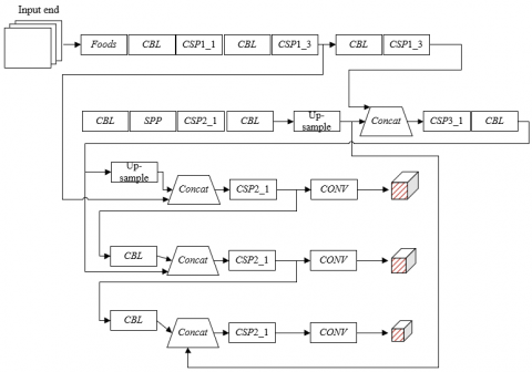
After finishing pre-processing and edge extraction of civil structure crack image, civil structure crack was detected in this article based on end-to-end object detection network YOLO. The used YOLO model is composed of backbone layer and detection layer. See Figure 3 for network structure. Civil structure crack image is segmented into several square grid cells through YOLO model, each of which is used to detect internal object crack. There are M bounding boxes able to be forecast, each of which is attached with coordinates of box size (f, q) and box center (a, b) and therefore a total of 5+D forecasts are made in confidence score and Class D probability. Suppose the probability of object in bounding box is expressed as Es(BO) and intersection-over-union (IoU) of real and predicated boxes as Γ(TB, PB), the formula of confidence score representing correctness probability of bounding box is expressed as:
$B B C=E_s(B O)^* \Gamma\left(\begin{array}{c}T B \\ P B\end{array}\right)$ (13)
The specific expression formula of Γ(TB, PB) is shown as below:
$\operatorname{IoV}\left(\begin{array}{l}T R \\ P R\end{array}\right)=\frac{\left(B O_{P R} \quad\cap B O_{T R}\quad\right)}{\left(B O_{P R} \quad\cup B O_{T R}\quad\right)}$ (14)
Loss function of YOLO model includes coordinate prediction error, intersection-over-union (IoU) error and classification error, which are respectively used to represent positioning accuracy of bounding box and overlapping degree and classification accuracy of edge and prediction box of grid cell. Suppose the weight of coordinate error is expressed as μCO, the number of grid cells of each detection layer as r2, the number of bounding boxes as Y, as for the issue on whether the target is in the jth bounding box of the ith grid cell and represented as LJBOij, the equation of definition of coordinate forecast error can be expressed as:
$E R_{C O}=\mu_{C O} \sum_{i=1}^{r^2} \sum_{j=1}^Y L J_{i j}^{B O}\left[\left(a_i-\overline{a_i}\right)^2+\left(b_i-\overline{b_i}\right)^2\right]$$+\mu_{C O} \sum_{i=1}^{r^2} \sum_{j=1}^Y L J_{i j}^{B O}\left[\left(q_i-\overline{q_i}\right)^2\left(f_i-\bar{f}_i\right)^2\right]$ (15)
Figure 3. Network structure of YOLO model
Suppose GT of each grid cell is expressed as (xi, yi, hi, wi), center coordinate, height and width of prediction box are respectively expressed as (ai*, bi*, hi*, wi*), object confidence penalty excluded in prediction box as μPU and authenticity confidence and prediction confidence are respectively expressed as Di and Di*, the equation of definition of intersection-over-union (IoU) error can be expressed as:
$E R_{\Gamma}=\sum_{i=1}^{r^2} \sum_{j=1}^Y L J_{i j}^{B O}\left[\left(D_i-D_i{ }^*\right)^2\right]$$+\mu_{P U} \sum_{i=1}^{r^2} \sum_{i=1}^Y L J_{i j}^{P U}\left[\left(D_i-D_i^*\right)^2\right]$ (16)
Suppose the detected class to which civil structural crack object belongs is expressed as D, and authenticity probability and prediction value of object as ei(d) and e'i(d), the equation of definition of classification error can be expressed as:
$E R_{C L}=\mu_{n o o b j} \sum_{i=1}^{r^2} \sum_{j=1}^Y L J_{i j}^{B O} \sum_{d \in \text { classes }}\left(e_i(d)-e_i^{\prime}(d)\right)^2$ (17)
By combining above error, the loss function of used YOLO model can be expressed as:
$L O S S=E R_{C O}+E R_{I o V}+E R_{d k r}$ (18)
Dataset of civil structure crack image used in this article includes 11,529 pictures. See Figure 1 for the number and proportion of images of specific transverse crack (Category 1), longitudinal crack (Category 2), irregular crack (Category 3), block crack (Category 4) and spray paint crack (Category 5) (Table 1).
Table 1. Number and proportion of civil structure crack attributes
|
Crack Category |
Number of Crack Images |
Proportion (%) |
|
Category 1 |
2147 |
18.62% |
|
Category 2 |
2063 |
17.89% |
|
Category 3 |
2581 |
22.38% |
|
Category 4 |
2697 |
23.39% |
|
Category 5 |
2041 |
17.70% |
Table 2. Experimental result comparison of crack edge detection
|
Sample |
Detection Method |
1# Crack Width |
2# Crack Width |
3# Crack Width |
4# Crack Width |
5# Crack Width |
|
1 |
Method 1 |
4.15 |
4.38 |
4.13 |
4.39 |
4.15 |
|
Method 2 |
5.36 |
5.69 |
5.24 |
5.27 |
5.12 |
|
|
2 |
Method 1 |
4.27 |
4.27 |
4.69 |
4.17 |
4.91 |
|
Method 2 |
4.16 |
4.03 |
4.17 |
4.93 |
4.28 |
|
|
3 |
Method 1 |
5.92 |
5.61 |
5.12 |
5.28 |
5.34 |
|
Method 2 |
5.71 |
5.48 |
5.37 |
5.47 |
5.61 |
|
|
4 |
Method 1 |
6.25 |
6.29 |
6.29 |
6.11 |
6.94 |
|
Method 2 |
6.48 |
6.74 |
6.57 |
6.93 |
6.28 |
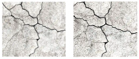
Figure 4 shows the pictures about crack image comparison after bidirectional filtration processing. After finishing image pre-processing, this article designs comparison experiment in order to check validity of the raised extraction algorithm for civil structure crack edge. The test method could improve subpixel edge detection algorithm (Method 1) and Sobel edge detection algorithm (Method 2). The experimental results are shown in Table 2, from which it can be learnt that the result fluctuation is greater when measuring geometric quantity of crack width with crack edge obtained as per Method 2, while measurement with crack edge obtained as per Method 1 is more accurate and deviation amplitude is smaller in case of crack width measurement for civil structure sample crack, meeting the requirements for construction accuracy.
Figure 4. Comparison picture of crack images after bidirectional filtration processing
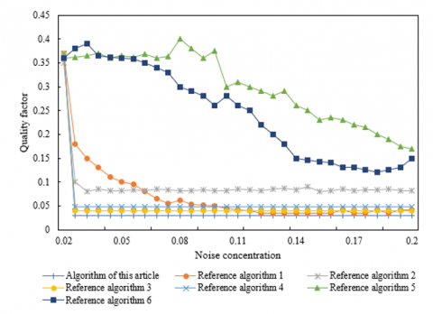
Figure 5. Influence of noise on crack edge detection performance
Figure 5 shows the results of comparison with other classic edge detections, including differential edge detection method (reference algorithm 1), Roberts operator (reference algorithm 2), Prewitt operator (reference algorithm 3), Lapras operator (reference algorithm 4), LoG operator (reference algorithm 5) and Canny operator ((reference algorithm 6). As shown by the figure, algorithm proposed in this article reaches its optimal status, when noise concentration is relatively low; in the meantime, with increase of noise concentration, the algorithm is always kept at high quality factor FOM and peak SNR (signal to noise ratio). It shows that lager non-maximum value area has stronger restraint against gaussian noise. For Sobel operator, peak SNR under gaussian noise and mean square error have better performance, but the quality factor FOM value isn’t as ideal as expected.
Reference models for performance comparison of civil structure crack detection model include Faster R-CNN, VGG-Unet, SCNN and SSD. See Table 3 for experimental results of all these algorithms. As shown in Table 3, model of this article will have higher detection accuracy rate and faster speed in self-made image dataset of civil structure crack. It was learnt through algorithm performance comparison, in comparison with other algorithms that are unsuitable for minor goal segmentation and have magnification operation oriented to characteristic pattern covered by candidate box, calculation quantity of model in this article is less, FPS is relatively high, accuracy rate reaches 95.42% and FPS value reaches 02, reaching the expected effect with respect to real-time detection task for civil structure crack in this article.
Table 3. Experimental result summary of different algorithms
|
Network Model |
Accuracy Ratio |
FPS |
|
Model of This Article |
95.42% |
92 |
|
Faster R-CNN[ |
91.04% |
42 |
|
VGG-Unet |
85.26% |
64 |
|
SCNN |
85.24% |
13.8 |
|
SSD |
71.48% |
42 |
|
Traditional image processing method |
63.92% |
-- |
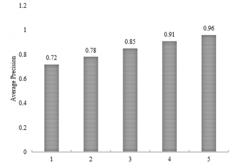
Figure 6. MAP result
Figure 6 shows the indicator MAP value of detection accuracy ratio of civil structure crack detection model established in this article. The indicator is mean value of area AP value under accuracy rate – recall rate curve of various crack categories. Compared with AP value, description of MAP for image dataset range is more accurate. According to Figure 6, AP value both of Category 4 and 5 exceeds 0.9, AP value of Category 3 crack reaches 0.85 and AP value of the another two categories is lower than 0.8. The main reason is that these two kinds of cracks are usually attached with discontinuous and irregular distribution characteristics and length of part of cracks is very short. By combining AP value of existing different categories of caracks, MAP value of the whole dataset is obtained as 0.844, relatively ideal.
This article is focused on the research on the image processing - based real-time detection method for civil structure crack. Bilateral filtration algorithm was used to smooth civil structure crack image. Interpolation calculation-based sub-pixel edge detection algorithm was used to extract civil structure crack edge, in order to obtain more accurate crack edge position. Civil structure crack was detected based on end-to-end object detection network YOLO. Experimental result shows the picture of crack image comparison after bidirectional filtration processing. The experimental result comparison of crack edge detection was completed, the influence of different noises on crack edge detection algorithm performance was analyzed and validity of the proposed extraction algorithm for civil structure crack edge was checked. Experimental result summary was given for civil structure crack recognition with different algorithms and MAP result distribution, to further verify real-time detection task for civil structure crack in this article reaches expected effect.
[1] Nuguzhinov, Z., Khabidolda, O., Bakirov, Z., Zholmagambetov, S., Kurokhtin, A., Tokanov, D. (2022). Regression dependences in bending reinforced concrete beam with cracks. Curved and Layered Structures, 9(1): 442-451. https://doi.org/10.1515/cls-2022-0182
[2] Li, D.S., Liao, G., Liu, Y., Luo, M., Wang, J., Dai, K. (2020). Concrete beam assessment based on fractal information of cracks. Proceedings of the fib Symposium 2020: Concrete Structures for Resilient Society, pp. 2062-2069,
[3] Wang, J., Li, L., Zhang, X.G., Zhao, Y. (2020). A Prediction Model for Concrete Cracks due to Chloride-Induced Corrosion. Advances in Materials Science and Engineering. https://doi.org/10.1155/2020/1049258
[4] Kuwabara, R., Kitamura, F., Obara, T., Kono, S., Mukai, T., Watanabe, H. (2020). Cracks observed in loading detection on five-story reinforced concrete building specimens and their numerical simulation. Journal of Structural and Construction Engineering, 85(771): 737-747. https://doi.org/10.3130/aijs.85.737
[5] Xie, X., Cai, J., Wang, H., Wang, Q., Xu, J., Zhou, Y., Zhou, B. (2022). Sparse-sensing and superpixel-based segmentation model for concrete cracks. Computer-Aided Civil and Infrastructure Engineering, 37(13): 1769-1784. https://doi.org/10.1111/mice.12903
[6] Singh, A., Kumar, R., Goel, P. (2022). Experimental Study on MOC Cement Based Micro Concrete for Repairing of Wide Cracks in Concrete Pavement Slabs. In Road and Airfield Pavement Technology, pp. 141-149. https://doi.org/10.1007/978-3-030-87379-0_10
[7] Zeng, Y., Zuo, Q., Jiang, S., Guo, M. Z., Wang, T., Chu, H. (2022). Effect of CTAB on the healing of concrete cracks repaired by electrodeposition and the durability of repaired concrete. Construction and Building Materials, 326: 126757. https://doi.org/10.1016/j.conbuildmat.2022.126757
[8] Kannan, U., Gafoor, S.A., Srivastava, S., Nithyadharan, M., Gupta, S.S., Maliyekkal, S.M. (2022). A waste-derived nanocomposite sealant for repairing micro-cracks in concrete. Journal of Building Engineering, 48: 103965. https://doi.org/10.1016/j.jobe.2021.103965
[9] Woo, H. J., Seo, D.M., Kim, M.S., Park, M.S., Hong, W.H., Baek, S.C. (2022). Localization of Cracks in Concrete Structures Using an Unmanned Aerial Vehicle. Sensors, 22(17): 6711. https://doi.org/10.3390/s22176711
[10] Mengel, L., Krauss, H.W., Lowke, D. (2020). Water transport through cracks in plain and reinforced concrete–Influencing factors and open questions. Construction and Building Materials, 254: 118990. https://doi.org/10.1016/j.conbuildmat.2020.118990
[11] Chen, E., Berrocal, C.G., Löfgren, I., Lundgren, K. (2020). Correlation between concrete cracks and corrosion characteristics of steel reinforcement in pre-cracked plain and fibre-reinforced concrete beams. Materials and Structures, 53(2): 1-22. https://doi.org/10.1617/s11527-020-01466-z
[12] Wang, X., Xu, J., Wang, Z., Yao, W. (2022). Use of recycled concrete aggregates as carriers for self-healing of concrete cracks by bacteria with high urease activity. Construction and Building Materials, 337: 127581. https://doi.org/10.1016/j.conbuildmat.2022.127581
[13] Cao, X., Li, T., Bai, J., Wei, Z. (2020). Identification and classification of surface cracks on concrete members based on image processing. Traitement du Signal, 37(3): 519-525. https://doi.org/10.18280/ts.370320
[14] Fu, R., Xu, H., Wang, Z., Shen, L., Cao, M., Liu, T., Novak, D. (2020). Enhanced intelligent identification of concrete cracks using multi-layered image preprocessing-aided convolutional neural networks. Sensors, 20(7): 2021. https://doi.org/10.3390/s20072021
[15] Geetha, G.K., Sim, S.H. (2022). Fast identification of concrete cracks using 1D deep learning and explainable artificial intelligence-based analysis. Automation in Construction, 143: 104572. https://doi.org/10.1016/j.autcon.2022.104572
[16] Zhu, J., Song, J. (2020). Weakly supervised network based intelligent identification of cracks in asphalt concrete bridge deck. Alexandria Engineering Journal, 59(3): 1307-1317. https://doi.org/10.1016/j.aej.2020.02.027
[17] Zhou, S., Pan, Y., Huang, X., Yang, D., Ding, Y., Duan, R. (2022). Crack Texture Feature Identification of Fiber Reinforced Concrete Based on Deep Learning. Materials, 15(11): 3940. https://doi.org/10.3390/ma15113940
[18] Xu, D., Liu, Q., Qin, Y., Chen, B. (2020). Analytical approach for crack identification of glass fiber reinforced polymer–sea sand concrete composite structures based on strain dissipations. Structural Health Monitoring, 20(5). https://doi.org/10.1177/1475921720974290