Pavel Egorov | Sergei Esin | Mikhail Gotovsky | Vitaly Lychakov* | Vladimir Mikhaylov | Ekaterina Sukhorukova | Yury Sukhorukov
OPEN ACCESS
Reheaters (LPR-3 and LPR-4). Heat exchange surfaces were made of welded or all-welded tubes of 08Х18Н10Т stainless steel (AISI 321) with a diameter of 16х1mm. LPR-3 and LPR-4 have identical design. The heating steam moves horizontally between the seven horizontal partitions and crossing successively vertical tubes of the second running and then the main condensate first running, condenses on the vertical heat exchange tubes and flows down along the tubes surface. The pressure in the tubes is about 1.2 MPa, and the pressure of the heating steam is 0.3 MPa. After the ban on the use of copper-containing materials in the second circuit of nuclear power plants, their gradual replacement began with steel ones. After a relatively recent installation of stainless steel tubes in LPR-3, significant damages of the tubes occurred with a violation of their tightness. Overwhelming majority of the damaged tubes were along the first running of the heated water and inside the three lower horizontal sections. The form of the damages appeared to be of a cavitation character, although the distribution of temperature and pressure did not completely satisfy this statement. It was shown that the presence of such effects can be explained using the model of internal non-stationary nature of two-phase flows proposed in the NPO CKTI JSC. Relative values of local pressure fluctuations correspond to the maximum of the density (or quality) fluctuations and can be about 0.03-0.05 MPa. Thus, the pulsations of local saturation temperature can reach 5-7°C and cause the effects of steam bubbles formation and their collapse in the condensate near the partitions. At the same time, it is possible to explain the location of the injuries and formulate some proposals for weakening or even elimination the observed effects. Although the described effects were found at NPP, but they, of course, can occur at conventional Power Plants.
low-pressure reheater, low-pressure regeneration system, perforating tube damage, cavitation damage, pulsation of void fraction
To ensure the reliability and service life of steam generators, increase the reliability and efficiency of the II circuit of the power units of NPP with VVER-1000, Rosenergoatom Concern decided not to use copper-containing materials in the heat-exchange equipment of this circuit. At present, the K-1000-60 / 1500 turbine units of Kalinin NPP and Balakovo NPP have low pressure heaters. The tube system was made of welded or seamless tubes of 08X18H10T steel with a diameter of 16x1 mm.
During the MM-2014 at the power unit No. 1 and the MM-2015 at the power unit No. 2 of Balakovo NPP, defects of 252 and 158 heat-exchange tubes were detected, respectively. Replacement of the HDPE-3 tube system at the power unit No. 2 was performed during the implementation of the PPR-2014.
This paper presents the results of a qualitative analysis of the causes of such multiple occurrences of defects in heat-exchanging tubes.
Low-pressure regeneration system of low-speed turbines К-1000 -60/1500, used at NPPs with VVER-1000 reactors, includes four low-pressure reheaters (LPR) - three-case LPR1-1, two-case LPR-2 and single-hull LPR-3 and LPR - 4. Heat exchange surfaces were made of welded or seamless tubes of 08Х18Н10Т steel with a diameter of 16х1 mm.
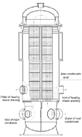
These LPRs have a lower location of the distribution and collection chamber of feedwater. All tube systems are similar and consist of straight vertical tubes with upper and lower tube boards and seven horizontal partitions. On the outside of LPR casing a special cover is installed, distributing the heating steam over the surface of the tube bundle and preventing drip erosion by throw water droplets onto the heat exchange tubes.
LPR-3 and LPR-4 have identical design (Figure 1). In the case on the side of the second stroke of the heated water, a window is located along the entire height of the tube bundle. The steam moves horizontally, passing successively firstly the second and then the first stroke of the main condensate, and condenses on the heat exchange tubes and flows downward. The pressure in the tubes is ~ 1.2 MPa, and the pressure of the heating steam is ~ 0.3 MPa.
The results obtained were described by formula (1), the terms entering into it are rather cumbersome and are not given here. The first term corresponds to the average heat transfer in the frontal part of the tubes and the second term corresponds to the aft part
$\alpha_{a v}=\alpha_{f r}\left(\varphi_{a v} / \pi\right)+\alpha_{a f t}\left(1-\varphi_{a v} / \pi\right)$ (1)
In the process of PM - 2014 at the Power Unit No. 1 and PM - 2015 at the Power Unit No. 2 of Balakovo NPP, defects of 252 and 158 heat exchange tubes were detected. Such a scale of damage was somewhat unexpected.
Reheaters LPR-3 and LPR-4 have identical geometrical sizes, quantity of heat exchange tubes, partitions and surfaces. However, the damage to the heat exchange tubes was detected only on LPR-3.
Figure 2 shows a map of the location of leaky, damaged and undamaged tubes. Damaged tubes are divided into two groups - tubes that have a leak and tubes that have a visual defect that was not detected by hydrotestings. But, as can be seen from the explanatory illustrations in the right part of Figure 3, the tubes of the second group have a distortion of the wall surface, characteristic for the loss of stability of the tubes under axial loads.
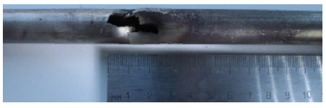
The nature of the damage that led to the violation of the density of the tubes was almost identical for all LPR-3 (Figure 3, 4). Damage was found in the zone of passage of the heat exchange tubes through the fifth, sixth and seventh partitions above the lower tube plate in the first (cold) stroke of the main condensate. They are oval dents 5-12 mm long and 2-4 mm deep with holes having various shapes and overall dimensions in the interval 1-3 mm with adjacent cracks. One of the assumptions was the hypothesis of their cavitation character [1].
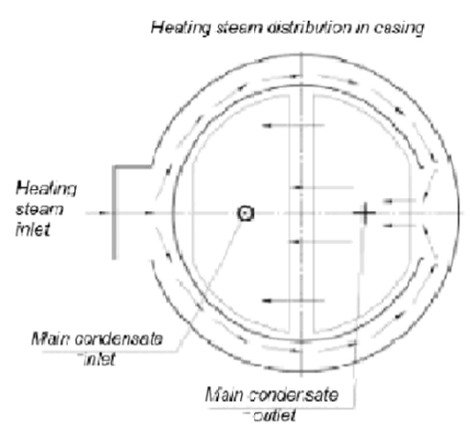
Figure 1. General view of the LPR – 3 construction and flow diagram of heated water and heating steam flows
Figure 2. Arrangement of damaged and undamaged tubes
However, as will be shown below, such a hypothesis is not supported by any specific considerations related to the nature of the motion of the vapor-liquid flow in the annular space.
The report of the chief engineer of the station gives the following statement of the detected phenomenon.
The view expressed by the NPP representative that the design of LPR-3 does not ensure the reliability of the heat exchange tubes in the central part of the "cold stroke" under the conditions of real operating parameters is confirmed by the cartogram shown in Figure 5. The location of the damage along the beam height and their character. We note that defects of the first type are located in the region of the fifth partition, and all the defective tubes are actually grouped in the central part of the "cold stroke".
It is known that cavitation processes are mainly manifested in the presence of significant fluctuations of pressures and velocities. This enables the formation of cavitation bubbles and their collapse. To implement the cavitation scenario, it is necessary to have a sufficiently thick layer of liquid on the surface of the tube.
Figure 3. The location of damage in height and their nature
Figure 4. Photos of fragments of a tube with perforating damage (Balakovo NPP)
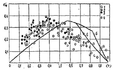
Figure 5. Dependence of the heat transfer coefficient upon condensation on the vapor pressure at q is 100 kW/m2 according to the experiments of Shilov, 1992. ○, ●, □, ■, ∆ - experimental points for the first (Ws=70 m/s), the third (Ws =40 m/s), fifth (Ws=30 m/s), the seventh (Ws - 25 m/s), the ninth (W> 20 m / s) row in the direction of travel of a condensing vapor calculation by formula (1)
Figure 6. The damages of the cavitation character, described in Schwartz [2]
This layer is just formed on the partitions. A similar type of damage is described and is shown in Figure 6. It was observed with periodic accumulation of steam in hard-to-reach places of the shell space.
Now, let us try to analyze qualitatively the possible formation of conditions for the appearance of cavitation in the apparatus under consideration. Why does such a problem arise? Heating steam transversely flows around a bundle of tubes and condenses on them, forming a film on the surface.
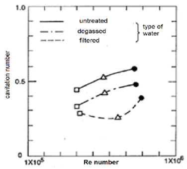
But the heating steam is practically at the pressure on the saturation line. When flowing through the tubes of each row, the flow accelerates, but the pressure drop is small at that. Another possibility of instantaneous local pressure reduction is the vibrations of the tubes, which always occur in the case of transverse flow around the bundles. For single-phase flows, this problem is discussed in detail in the monograph by AA Zhukauskas et al. and Plotnikov, Shishkin [3-5]. It is important to note that the boundary of the onset of cavitation essentially depends on the purity of the liquid (Figure 7).
Figure 7. An example of the effect of water purity on the probability of cavitation
Let us now consider the qualitative nature of the evolution of the flow of steam as it moves across a bundle of tubes with heated feed water. Note first that the beam forming the condensation surface is very dense. The relative pitch of the hexagonal package is 1.37. Naturally, as a result of condensation, the steam flow rate and its speed are decreased. Essential vibrations can occur in beams with a small transverse pitch ("dense bundles"). However, in our case this factor cannot be regarded as predominant. Even taking into account additional local pressure pulsations caused by vibration cannot change this conclusion. By the way, the damage should have a fatigue character.
Therefore, the idea arose to address the consideration of specific vibrations caused by the internal non-stationarity of two-phase flows (this term was introduced by Fokin in the 1980s and 1990s [1, 6]. The results of these studies were proved in assessing the vibrations of steam generating tubes in large-scale models of vertical steam generators of nuclear power plants, which were experimentally investigated in Polzunov institute in the 1980s. In these studies, it was shown that the intensity of pressure and vapor content pulsations depends on the flow regime of the two-phase mixture, and its maximum value is observed near the transition zone from intermittent to ring mode (see Figure 8). This Figure does not give a 100% clear idea of the position of the maximum density ripple due to an unsuccessful choice of the variable, plotted along the abscissa axis. However, the presence of a maximum shifted to a high humidity region is obvious. We will see below that this concept is in an agreement with the data on the tube damage shown in Fig 4. It also should be noted that the values of the amplitude of pulsations of volumetric vapor content given in Figure 8 are attributed to its mean value. This makes it possible to expect significant pulsations of pressure.
Figure 8. Dependence of rms amplitude of pulsations of gas or vapor void fraction from its average value. Experimental data: 1 – Polzunov institute, air-water, D=10 mm, W0=0.4,…8 m/s; p=0.1,…0.2MPa; 2 – physics-power institute air-water, D=18 mm, W0=0.2,…2 m/s; p=0.1MPa; 3 – physics-power institute steam-water, D=21 mm, W0=0.3,…2.7 m/s; p=0.1 …7 MPa; 4 – Polzunov institute, air-water, D=20 mm, W0=0.4,…1.8 m/s; p=0.15MPa; 5, 6 – non-stationary model calculation Г0=800, 20 respectively
The amount of liquid in flat planar horizontal tracts with condensing steam gradually grows when passing to the lower tracts. Due to the mechanical interaction of the steam with the condensate during flow through the gaps between the tubes in the shell space, a two-phase mixture with the largest moisture content near the partitions is formed. Thus, as the steam velocity decreases, we enter the zone of the intermittent regime, which for the structure under consideration is located in the part of the bundle heating the water in the first stroke of the main condensate. The maximum temperature head between the heating steam and the heated main condensate takes place in the lower part of the first stroke, as a result of which the accumulation of the condensate of the heating steam takes place here most intensively and contributes to the formation of this zone. Its exact location is difficult to determine, but, at any rate, it should be markedly shifted to the side opposite to the input of the heating steam. The values of local pressure fluctuations in relative values will correspond to the steam-water density (or steam quality) pulsations and, according to Figure 7, taking into account the level of pressure in the annular space, can be of the order of 0.03-0.05 MPa. In this case, the pulsations of the local saturation temperature can reach 5-7 °C
One can express an idea, that the appearance of through damage is the second stage of deformation of the tubes after the appearance of a wavy surface.
It is important to note that with such low overheating it would be difficult to determine the specific position of the defective tubes, but in this case their compact arrangement proves the correctness of the adopted process approximate model.
In the lower Figure channel, the effects indicated here can be somewhat strengthened due to the effect of the cascade drain of the steam condensate from the LPR-4.
We note that the estimates, which results are given in Trifonov et al. show that about 60% of the total heating of the condensate occurs on 40% of the surface along the course of the main condensate [7]. That is, much more than half of the total amount of heat is transferred to the lift site. Given that the temperature head is at its maximum, there is nothing surprising in this. but in the same paper it is mentioned that LPR-3 is somewhat overloaded in terms of thermal load in comparison with other LPRs.
Since some of the devices having a similar design did not show such significant damage and the results obtained with some not too large changes in the mode parameters, then a detuning from the mode in question is possible.
Therefore, if practical design conditions lead to the need of similar design usage, then a thorough experimental study of the operation of the apparatus is necessary in order to choose a safe mode of operation. In particular, this leads to the idea that when the direction of movement of the main condensate changes, it is possible to eliminate, or at least significantly reduce the damage to heat exchange tubes. Since the temperature of the heating medium is practically unchanged, such a correction will not lead to a significant change in the amount of transferred heat.
Thus, the results show that when choosing the design of feedwater heaters in the form of vertical bundles of tubes that are transversely flowing through the condensing vapor, a careful evaluation of the thickness of the condensate layer on the lower horizontal partitions is necessary to avoid damage to the heat exchange tubes described in the paper.
[1] Fedorovich, E.D., Fokin, B.S., Axelrod, A.F., Goldberg, E.N. (1989). Vibration of NPP equipment elements. Moscow: Energoatomizdat.
[2] Schwartz, M.P. (1982). Four types of heat exchanger failures. ITT Bell & Gosset.
[3] Zhukauskas, A.A. (1982). Convective transfer in heat exchangers. Moscow: Nauka.
[4] Plotnikov, P.N. (2004). Providing and increasing the reliability of shell-and-tube heat exchangers for steam turbine installations. Doct. diss.,Thesis, Ekaterinburg.
[5] Shishkin, B.V. (2013). Strength and vibration of shell-and-tube heat exchangers. Komsomolsk-on-Amur.
[6] Fokin, B.S. (1992). Development of methods for calculating the pulsational and averaged characteristics of a two-phase flow based on the principle of minimum energy dissipation. Doct. Diss. Thesis, SPb
[7] Trifonov, N.N, Esin, S.B, Nikolaenkova, E.K, Sukhorukov, Y.G., Svyatkin, F.A, Sintsova, T.G., Modestov, V.S. (2017). Probable causes of damage to heat exchanging tubes of LPR-3 and ways of their elimination. Thermal engineering, 64(8): 268-273.