Rabie Hamidane*![]() | Leila Hayet Mouss
| Leila Hayet Mouss![]() | Rafik Mahdaoui
| Rafik Mahdaoui![]() | Toufik Bentrcia
| Toufik Bentrcia![]()
© 2024 The authors. This article is published by IIETA and is licensed under the CC BY 4.0 license (http://creativecommons.org/licenses/by/4.0/).
OPEN ACCESS
Maintenance, storage and warehousing are complex processes required in many industries such as automotive, aerospace, manufacturing and logistic companies. These processes, often, involve moving objects in crowded environments using robots or human operators. Particularly, replacement and assembly of machine parts in crowded environments when performed by a human being require high technical skills. These tasks may be performed using robots to reduce costs due to human errors and execution time. However, robots under open world assumptions could neither operate in all environments nor perform tasks not modeled by the designer. In this paper, we introduce a mixed reality system to assist human operators in moving objects in crowded environments for maintenance tasks such as: parts assembly or replacement, and storage of objects. The introduced system consists of a mobile application exploited through a hands-free VR box. The proposed Mixed Reality for Industrial Maintenance (MRIM) system enhances the perception of a human operator by overlaying 3D real world visual information and virtual objects, such as: orientation guidelines including rotating angles, moving direction and displacement of carried objects. These guidelines allow for gaining execution time, and reducing human errors that might cause industrial parts damage. The proposed work brings two main contributions. First, it makes use of a new algorithm based on recasting, named R star (R*) that allows for optimizing pathfinding in 3D space. This later outperforms the two commonly used baseline 3D pathfinding algorithms of at least 87.5% in terms of execution time. Second, MRIM provides an easy-to-use interface that exploits information provided by the R* algorithm. The experiments, conducted in real condition for the task of part replacement in a crowded environment, show that MRIM reduces considerably execution time and human errors.
industrial maintenance, mixed reality, pathfinding, 3D interaction
The industrial sector often requires automation of many tasks such as: maintenance, storage and warehousing. These later, generally, represent complex processes needed in many industries including automotive, aerospace, manufacturing and logistics. These processes involve moving objects in different types of environments using robots or highly trained manpower. Specifically, in the domain of maintenance, for instance, General Electric company makes use of robotic systems for predictive maintenance of its power plants and aircraft engines [1]. Robots are helpful in sectors where continuous and constant monitoring and maintenance are needed such as: manufacturing and electricity generation (https://www.industryweek.com/). Unfortunately, even though, robots are efficient at doing repetitive tasks; they fail to deal with unforeseen environments or jobs that may involve creativity [2]. Moreover, implementing robotic systems involves significant upfront costs, including their purchase, setting up the necessary infrastructure, and training personnel which may be an insupportable burden for small and medium-sized companies.
Moreover, using manpower, for multiple tasks may lead to execution constraints, specifically, for maintenance beginner technicians; which may eventually yield frequent procedural errors and thus increases maintenance costs and time waste. Effectively, a research conducted by the International Society of Automation (ISA) revealed that over 23% of unplanned downtime in industrial settings is caused by human error. Downtime might cost $260,000 per hour on average in the manufacturing sector (https://www.isa.org/). This is mainly due to personnel lack of experience. For instance, novice technicians could unintentionally increase this downtime by installing parts incorrectly or failing to follow the right procedures. Therefore, technicians must be well trained on their respective given tasks. Moreover, another problem that requires a lot of experience and precision is noble parts placement in crowded places. Effectively, this process becomes harder when it requires following only limited paths to set up parts in target places.
These issues need to be addressed, specifically by integrating new technologies to provide human technicians with assistance tools to perform tasks where a robot would fail, particularly, in crowded places and for unseen circumstances. Besides, in the context of high global competition, the manufacturers need to enhance personnel productivity by providing technical assistance efficiency.
We believe that Mixed Reality (MR) when leveraged for the aforementioned processes, specifically for maintenance tasks including parts assembly or replacement, and storage of objects that involve objects moving, may allow human technicians gaining in performances. Effectively, this technology could enhance the perception of a human operator by overlaying 3D real world visual information and virtual objects such as: orientation instructions including rotating angles, moving direction and displacement of carried objects. The proposed Mixed Reality for Industrial Maintenance (MRIM) is a MR based applications for smartphones that can be used through a hands-free VR box. In addition to an easy-to-use interface, MRIM uses a newly proposed algorithm for pathfinding in 3D space to allow adding distance information and orientation instructions to the users precepted mixed environment. In the literature, few pathfinding in 3D space algorithms were proposed [3-14]. However, these later present some drawbacks, particularly, they explore systematically all paths to target which affects the performances and needs to be improved. To this purpose, we introduce a new pathfinding algorithm in 3D space named R*. The proposed algorithm is based on ray casting; it consists of following a permanent ray from source to target, if the target is not reachable by mean of this ray, other rays are created following an optimized criterion. The new algorithm R* uses object dimensions to find a path even in a crowded situation, it is also deterministic since it finds the same path using the same initial conditions, and it speeds up motion planning process. The experiments show that the proposed R* algorithm outperforms the existing algorithms, which is essentially due to the restriction on the explored paths, allowed by a gradual prospection of a crossing space for the object, in contrast with the state-of-the-art algorithms that explore systematically all paths to target.
To the best of our knowledge, MRIM is the first proposed mixed reality system that optimizes tasks that involve objects moving such as: parts assembling in crowded environments. Basically, MRIM allows multiple functionalities such as: assisting and supporting modern monitoring via mixed reality, reducing manipulation and maintenance burdens, preventing systems from failure, calculating the path in 3D space in real-time, and inserting objects in a mixed reality that indicates the path to the target.
This manuscript is organized as follows. Section 2 introduces the state-of-the-art; it treats maintenance systems based on MR and pathfinding algorithms in 3D space. Section 3 presents our proposed system. Section 4 describes MRIM implementation and tests in real conditions. Section 5 is devoted to system evaluation and comparison. Finally, section 6 concludes the present paper.
Nowadays, companies aim at optimizing cost, quality and time. Hence, maintenance, despite its high cost, is one of the essential solutions. The integration of new technologies in the field of maintenance led to several research works based on intelligent vision techniques that exploit mixed reality and pathfinding in 3D space for some specific applications. These techniques can be categorized as AR-based (terms AR and MR are used interchangeably) general maintenance systems, or AR-based collaborative and remote systems.
2.1 AR-based general maintenance systems
Augmented reality (AR) was used as a new technology for maintenance; systems such as STARMATE [15] were developed for assisting technicians to perform their tasks in complex mechanical systems. In the same optic, Didier [10] introduced a maintenance system to guide users by adopting mobile AR. The proposed system was developed to describe steps of scenarios to facilitate the maintenance of industrial equipments, and to offer a tool for remote guided collaborative maintenance. In 2006, Riess and Stricker [16] developed ULTRA, a portable software architecture that supports on-site maintenance and provides AR manuals for users. In the same year, Platonov et al. [17] proposed for BMW company a new augmented-reality-based automotive maintenance prototype using a transparent system. Later, Zenati contributes to the design and the implementation of an
AR system for maintenance [18]. Benbelkacem et al. [19] introduced an AR system to train and assist maintenance technicians in the maintenance of industrial equipments. In 2011, the ARMAR project [11] was initiated to study and explore the effects of AR technology on increasing the productivity, accuracy and safety of maintenance personnel. Recently, Malta et al. proposed a system based on a deep learning neural network for recognizing some of the constituent parts of an automobile [20]. Later, Ortega et al proposed a new system of maintenance called AR-MANTRA that combines both AR and infrared thermography technologies [21].
2.2 Based-AR collaborative and remote systems
Some works were proposed in the literature for collaborative and remote systems maintenance, such supervision of collaborative industrial maintenance task proposed by authors in the study [6]. In the study [22], a collaborative, real-time remote assistance system was proposed. This latter is based on hand gestures-dependent mobile AR and can be exploited by a distant user. Later, Zenati et al. [23] integrated electronic maintenance into the later system for better usability. In the same context, Mourtzis et al. [24] presented a typical application for remote maintenance support, where the technicians are capable of performing maintenance operations by manipulating a robotic arm with the use of AR-projected instructions. Later, in 2018, Mourtzis et al. [25] covered another aspect of AR-based remote maintenance under the framework of Product Service Systems (PSS). Therefore, the AR tools developed enable manufacturers to add value to their product line by switching to the PSS concept. In 2019, Bottani et al. conducted a study to analyze and review the scientific literature related to AR-technology applications in industry [5]. Later, Mourtzis et al. [26] proposed a real-time remote maintenance support based on AR using cloud computing. Later, Runji et al. [27] presented a study on user-requirements analysis for AR-based maintenance. In the same context, Marques et al. [28] presented an analytical study to determine the extent to which AR technology can be used in Remote Collaboration in Maintenance.
2.3 Pathfinding in 3D space
Research projects that focus on finding 3D spatial trajectories can be categorized into two main classes, namely deterministic and probabilistic methods. The first class ensures finding the same path given the same initial conditions [7, 14]. Where, the second class includes probabilistic methods that are not complete in resolution, but offers a solution if it exists. These methods said to be complete in probability, do not necessarily find the same path for each execution, even with similar initial conditions. Probabilistic methods can be divided into two sub-groups, sampling methods and dissemination methods. The former seeks to approximate the environment of the object to be moved, to build a reusable map in the same way as a roadmap. The second performs a random search in the environment, until the desired final configuration is found. In the literature, some well-known algorithms were developed; such as, breadcrumb algorithm, probabilistic roadmap (PRM) for sampling methods, and rapidly exploring random trees (RRT) for dissemination methods.
Some works were proposed in the literature for pathfinding in 2D and 3D spaces. A cooperation method between human and automatic motion planners is proposed in the study [13]. This method exploits haptic devices to guide, control and improve the interaction between the moved object and the obstacles [4, 9, 12, 29,]. Traditionally, the motion-planning problem concerns an object movement in an empty space or workspace from the source to the target including obstacle avoidance strategies. Specifically, some other works aim to plan the displacement on the surface of obstacles [30-32]. In this context, Blin et al [3] implemented a RRT interactive contact algorithm (I-RRT-C). This work introduces a real-time interactive layout, where a computer and a human operator collaborate to explore the workspace simultaneously. To this purpose, authors combined two techniques, the use of the RRT algorithm and human interaction to minimize unnecessary time and paths; leading to a semi-automatic system which performances are affected by the operator gesture. More recently, Cailhol et al. [7] proposed an original multilayer interactive solution based on two steps. First, the proposed system seeks for a topological path in the environment, and then it uses geometric information to control a targeted object. Both stages are managed based on semantic information. In this work, the authors consider the workspace as a 3D grid, and use the Dijkstra algorithm to find a path. However, this technique presents some drawbacks. Effectively, first, the information characterizing the object (position and rotation) remains the same during its movement from the source to the target, second this technique is very slow [7]. Table 1 shows the comparison features between RRT and I-RRT-C algorithms.
Table 1. Comparison features between RRT and I-RRT-C algorithms
|
Feature |
RRT |
I-RRT-C |
|
Algorithm type |
Deterministic |
Probabilistic with human Interactive |
|
Time of execution |
Slow |
Fast |
|
User interaction |
None |
Yes (for path correction) |
|
Complexity of computation |
Lower (Automated process) |
Higher (Requires human interaction) |
|
Avoiding obstacles |
Automatic but can create unnecessary paths |
Improved with human input to avoid obstacles better |
|
Real-time application |
Restricted, better suited for prearranged routes |
Appropriate for real-time route planning and modification |
|
Flexibility |
Less flexible, depends heavily on initial conditions |
More flexible due to adaptive human adjustments |
Most of the approaches presented in the field of movement planning, whether deterministic or probabilistic algorithms are relatively time-consuming, especially in complex spaces like congested and narrow passages. Effectively, the algorithms used in these approaches create unnecessary paths even with the involvement of a human operator to determine the plan. Due to the drawbacks of the aforementioned approaches, it becomes necessary to introduce a new automatic motion-planning algorithm that minimizes useless paths, and takes into consideration object dimensions to optimize pathfinding process.
The lack of systems that combine both pathfinding in 3D space and mixed reality, and the drawbacks of pathfinding algorithms, motivate the proposed new system called MRIM introduced in this manuscript. This latter is based on mixed reality and pathfinding to optimize industrial parts movement in 3D space.
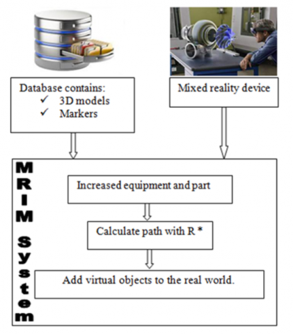
The proposed mixed reality system called MRIM consists of a combination a friendly user interface and a new pathfinding algorithm in 3D space named R*. As shown in Figure 1 that depicts the full process of the proposed approach, MRIM is mainly composed of three modules. The first module augments the environment by inserting virtual objects from the real word using the pre-created database that contains virtual objects, and markers such as directional rows. The second module finds the best path necessary for objects movement, and finally the last module adds the virtual indications to the best path.
The proposed mixed reality system MRIM, is introduced to assist technicians in the task of mounting a replacement part in a crowded place which requires when executed manually a lot of experience. The system MRIM requires to operate a 3D model as a working environment and a 3D model of the part to be moved. To develop MRIM, the well-known Augmented Reality Toolkit ARToolkit v5.3.2r1 was used (Wagner and Schmalstieg, 2007) for the augmentation of the work environment and the part, and to ensure a good tracking through the interaction with users. After running R*, the output vector V, containing information about the path to follow to target, is used by MRIM to add virtual objects (3D annotations and indications) in the real world that assists the technician to put the part in their corresponding positions.
The proposed system MRIM is based upon a new pathfinding in 3D space algorithm that optimizes path search. This latter called R* uses rays that points from source to target to find the path and avoid obstacles. Experiments indicate that the proposed R* algorithm performs better than the current algorithms. This is mainly because it restricts the explored paths, which is made possible by gradually prospecting a crossing space for the object. In contrast, state-of-the-art algorithms systematically explore all paths to the target. The algorithm R* consists of several steps, First, object initial position and rotation are collected in a matrix M represented in Eq. (1).
$M_{i j}=\left[\begin{array}{ll}P_x & R_x \\ P_y & R_y \\ P_z & R_z\end{array}\right]$ (1)
where, M represents a node in the path from source to target. As a second step, a permanent ray from the object to target is created. Then, if this later hits the target, the object is moved directly to its position, as shown in Figure 2(a). If the ray hits an object other than the target considered as an obstacle (Figure 2(b)), the distance L from the object to the hit point is saved. Then, a surrounding circle of points of a radius R is created around the hit point as shown in Figure 2(c). If all the points of this circle rely on the hit object, then the size of radius R should be increased until some points of the circle go beyond the obstacle edges; which will indicate an eventual crossing space. Radius R size is updated according to the object dimension selected by the user interacting with MRIM system, and its properties are specified by Eq. (2) and Eq. (3).
$R<=D D$ (2)
$R=\frac{d}{2} \times j$ (3)
where, DD is the width of workspace, d stands for the size of the object dimension selected by user, and index j is a multiplier that is initialized to 1. Intuitively, equation 3 means that the radius R is chosen as a multiple of the dimension size of the object to be moved. The number Nbp of points of the circle is fixed according to the object dimension, such as the distance between each two points of the circle equals the object dimension d, as indicated by Eq. (4) and Eq. (5).
$N b p=360 / \Theta$ (4)
$\Theta=2 \times \sin ^{-1} \frac{d}{4 \times R}$ (5)
Once the virtual circle created, a ray is projected from the object to be moved to each point of the circle, if the ray hits an obstacle then the next point is checked. If all rays hit the obstacle, then the radius R is increased according to equation 3 (see Figure 2(d)). Finally, if a ray does not hit the constraint; then the length and the width of the detected eventual crossing space are calculated to check if the object fits and which object rotation should be applied to allow its movement as shown in Figure 2(e). Then, the object is moved by a distance L into the center of this eventual crossing space (see Figure 2(f)). The new position and rotation of each movement step k will constitute the kth-component of a vector V representing the path from source to target. The algorithm will reiterate until the object reaches the target. Algorithms below describes in more details R*.
Figure 1. Proposed approach and MRIM architecture
Figure 2. Description R* algorithm (a) Movement of the object to target, (b) Ray hit an obstacle, (c) System creates a circle of points, (d) Circle is enlarged, (e) Verify if the object fits, (f) Object moves to the new position
Input:
O: 3D object with Op the object position centroid (center of object).
T: the target with Tp the target position centroid (center of target).
DD is the width of workspace.
d = dimension of object/2
l = length of object
w = width of object
h = height of object
R =d
i =1, j =1, a = 0
Output:
Mij represents a matrix of six elements saving the position and the rotation of object,
Vi vector of matrix Mij saving the position and the rotation of object for each movement (path information).
Ci vector of 3D points for saving the information of the position of point created on the circle.
Algorithm 1
|
Begin
i++; j = 1; $a$ = 0; go to 4
|
Verify_if_object_fit (Px,Py,Pz): Boolean
Algorithm 2
|
Begin
if the object fit then begin Save the new position and rotation in the matrix Mij. Vi: = Mij Return true End else Return false End. |
The proposed system MRIM was implemented using Unity3D, Visual Studio C 2015 and ARToolKit package version 5.0. The experiments were conducted on a PC with a I7-2670QM CPU 2.20GHz Intel® Core™ and 8GB of RAM. We implemented two versions of this system, a Windows version to be used on Windows 10 Tablets and an Android version, to be used on a Smartphone mounted on cardboard. For the following tests, the Smartphone version was used to allow technicians to operate hands free.
4.1 Test protocol
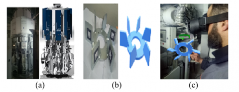
The proposed system was evaluated in real conditions, in a Cement Factory situated in Elma-Labiod city located in the eastern border of Algeria, administratively attached to the wilaya of Tébessa. This plant, built by the Danish Factory FLS in nineties and equipped with a single line of production, has a production capacity about six hundred thousand tons per year. The tests were performed on the Cement Packer Machine called HAVER BOECKER ROTO-PACKER. This machine is used to fill bags with cement (see Figure 3(a)), it uses a complex rotating mechanical system. This latter breaks down frequently which leads to a frequent maintenance that requires expert intervention.
Twenty technicians from the factory were involved during the test to use MRIM system for replacing a spare part that include mounting a fan, that represents a spare part, in a sensitive environment due to the crowded path. For this specific task, the selected part of the conducted test is depicted in Figure 3(b). Figure 3(c) shows the technician following the system 3D virtual indications for changing the worn part. The accuracy of the execution of the task represents how effectively the task was executed properly. This is evaluated by measuring automatically, by the proposed system, the distance between the centers of both the targeted emplacement and the spare part. As a limitation of using MRIM, the virtualization of the environment needs specifics tools to scan the 3D objects; if these later do not present size constraints, otherwise the virtualized object should be provided by specialized designers. Fortunately, in our specific case the 3D model of the aforementioned machine was provided by the manufacturer.
Figure 3. Real and virtual model, (a) haver boecker roto-packer, (b) spare part, (c) technician using the system
4.2 Hypothesis test
To compare the time and accuracy needed to conduct the task of replacing spare parts in a congested place with and without the use of the proposed MRIM system, we conducted a hypotheses test based on two variables namely Execution time and Accuracy. We defined the following two hypotheses.
1. H0: the execution time of a given task with the system is less (better) than without the system;
2. H1: accuracy of performing a given task with the use of the system is better than without the system.
Two groups of 20 participants were considered in this test, each group includes 8 females and 12 males with ages ranging from 22 to 50 years. The participants belong to different domains of expertise, 10 persons are employees of the Cement Factory and three of them are operators on the machine used for tests. The remaining participants do not have any skills in maintenance field. It should also be noted that all participants do not present any health problems.
The participants with and without skills were familiarized with the device manipulations and system operation. The participants were organized into two groups to perform the test alternately with and without the proposed system twice. Each participant was equipped with a AR headset combined to a Smartphone including an android version of MRIM system.
For each experiment, the execution time was recorded as well as the accuracy representing the discrepancy in millimeters when setting up the part in its place.
4.2.1 Objective evaluation
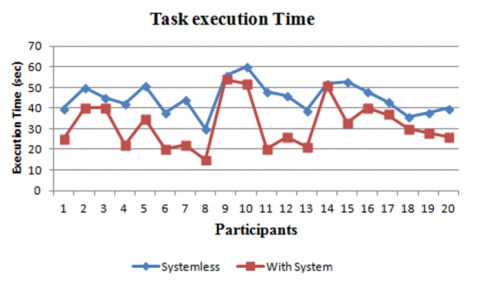
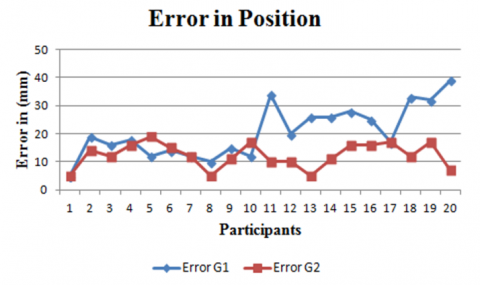
A Paired-Samples t-test was conducted on the collected data using IBM SPSS Statistics version 20 to study the behavior of MRIM system in terms of execution time and accuracy. The results obtained for the first group are (T=8.012, p<0.007) for the time-to-completion task and (T=6.724, p<0.002) for the precision task. This reveals a significant impact of our system on the indicators of time and precision. Overall, as shown in Figures 4 and 5, most of the participants completed the tasks faster and more accurately while using MRIM system.
Hypothesis H0 is accepted since p-value is less than 5%. Therefore, there are statistical differences in the effectiveness of using the system compared to not using it on the level of execution time and accuracy. Table 2 shows the results of the comparison of the mean execution time and the mean error in both cases. These results suggest that the two metrics values in case of using MRIM system are less than when performing the task manually.
Figure 4. Mean execution time per participant for the first group
Figure 5. Mean error per participant for the first group
Table 2. Mean execution time and mean error in both cases for the first group
|
|
Mean Execution Time |
Mean Error |
Standard Deviation |
|
Systemless |
44.95 |
27.30 |
7.409 |
|
with system |
31.85 |
20.05 |
11.495 |
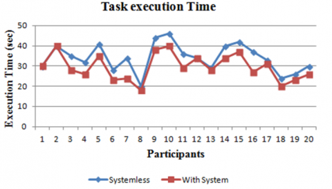
Through this analysis, we conclude that for the first group, using the system led to better results compared to the case without the system. The results obtained for the second group are (T=6.669, p<0.004) for task completion time and (T=4.042, p<0.001) for the precision task. As shown Figures 6 and 7, the use of MRIM system has an important impact of on execution time and precision. It can be noticed that, overall, most participants performed tasks more accurately and with less time consuming while using the system.
Similarly, the first group, hypothesis H1 is accepted since p-value is less than 5%. Therefore, for the second group, there are significant increase in performances in terms time execution and accuracy when MRIM is used to perform the desired task. The results shown in Table 3 suggest that mean execution time and mean error in the case of using the system were optimized when using MRIM system.
Figure 6. Mean execution time per participant for the second group
Figure 7. Mean error per participant for the second group
Figure 8. Mean execution time per participant for both groups
Table 3. Mean execution time and mean error in both cases for the second group
|
|
Mean Execution Time |
Mean Error |
Standard Deviation |
|
Systemless |
34.05 |
15.25 |
6.886 |
|
with system |
29.55 |
13.00 |
6.468 |
In order to determine which group performances were optimized when using MRIM system, we performed an Independent-Sample t-test on data collected using IBM SPSS Statistics Version 20 to study. To this purpose, we defined the following two hypotheses for each variable namely Execution time and Accuracy.
1. H0: the execution time of the task with our system in the first group is different than the execution time in the second group;
2. H1: accuracy of performing a given task with the use of the system is different for the first group than for the second group.
The results obtained for this test are (T=0.780, p<0.440) for completion time and (T=3.402, p<0.002) for accuracy. Figures 8 and 9 illustrate the obtained results that suggest a significant impact on performances when using MRIM to perform the desired task for both groups.
Figure 9. Mean error per participant for both groups
Hypotheses H0 is rejected since p-value of execution time is higher than 5%, consequently, there are no statistically significant differences between execution time associated to both groups. Conversely, hypothesis H1 is accepted for the accuracy given that the p-value is less than 5%. Hence, there are statistically significant differences between the accuracy for both groups. Moreover, the comparison of mean error for both groups suggests that participants of the second group performed better those of the first group in terms of precision. Therefore, the error rate in the second group is minimal compared to the first group. Thus, we can find any difference between the two groups in execution time or error using the Coefficient of Variation (CV) using the following formula:
$C V=\frac{S}{\bar{x}} \times 100$
S represents the standard deviation and $\bar{x}$ denotes the mean.
CV for execution time
First group: $C V=\frac{11.495}{31.85} \times 100=36.1 \%$
Second group: $\mathrm{CV}=\frac{6.468}{29.55} \times 100=21.9 \%$
CV for accuracy
First group: $C V=\frac{11.495}{20.05} \times 100=57.33 \%$
Second group: $C V=\frac{6.468}{13.00} \times 100=49.75 \%$
We notice that the coefficient of variation of the second group is less than that of the first, so the second group gains more advantages from the exploitation of our system.
4.2.2 Subjective evaluation
Immediately after the completion of all experiments, participants from both groups were given a questionnaire to rank the two methods. To achieve this purpose, we used the Utility, Satisfaction and Ease (USE) questionnaire [33].
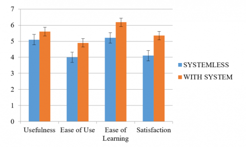
According to the results of the questionnaires, most of the participants estimated the simplicity of our system and usability see Figure 10. For utility questions, we noticed that the responses of the participants in each group were globally identical when using the system. In addition, they mentioned the ease and efficiency of our system.
Figure 10. Usability evaluation for both systemless and with system
Besides, the participants were asked to give their opinion about physical exertion and psychological pressure. The majority of respondents found that using the system makes them less stressful, compared with no system. In addition, participants rated our system as an indispensable tool for maintenance and assembly tasks, they also classified the system as a learning tool for beginners.
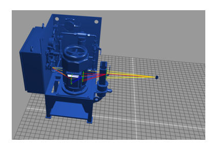
To assess the performances of our proposed algorithm R*, designed for pathfinding in 3D space used in our system MRIM, we conducted an experiment that consists of moving a mechanical part from a source to a given target place in a simple virtual work space of a cubical form. Figure 11 depicts the experimental environment where an engine is moved to its final emplacement to be assembled to a machine represented in blue. Yellow and red rays indicate paths provided by R* algorithm and colours indicate the algorithm steps.
Figure 11. Work space
Figure 12. (a) Algorithm RRT, (b) Algorithm I-RRTC, (c) Algorithm R*
Besides, we considered the commonly used algorithms as baselines for performances comparison, namely, RRT [13] and I-RRT-C [2]. Our algorithm R* and the baselines where compared in terms of execution time, and number of generated nodes (represented by the angular points of edges) and edges, these later represent the moving steps of the tested paths as shown in Figure 12. The results reported in Table 4 show clearly that our proposed algorithm R* outperforms all baselines in terms of all metrics. Effectively, R* performs at least 87.5%, 93.46%, 93.54% respectively in terms of time, number of generated nodes and edges better that all baselines. Besides, Figure 12 visualizes the extent to which the performances of R* are better than baselines ones in terms of nodes and edges numbers, that is clearly highlighted by the density of edges.
Table 4. Results of experiences
|
Scenario |
Time |
Nodes |
Edges |
|
Simple RRT |
1h8m |
4670 |
9338 |
|
I-RRT-C |
12m |
1224 |
2446 |
|
R* |
13s |
20 |
38 |
The proposed system MRIM for mixed-reality based maintenance shows good performances in terms of usefulness, ease of use and satisfaction. Moreover, it exploits the proposed pathfinding algorithm R* that outperforms all baseline in terms of all metrics. However, MRIM presents some drawbacks, it requires a virtual 3D model of the workspace and it is effective only if parts to be moved are of cubic shape. To overcome these latter, we suggest to enclose parts of unrecognized forms in a cube or a cuboid.
The introduced system MRIM can be used for several complex tasks, involving moving objects in crowded environments, including Maintenance, storage and warehousing required in many industries such as automotive, aerospace, manufacturing and logistic companies. Effectively, it can reduce considerably the costs related to unexperimented manpower and gaining execution time.
In this paper, we introduced MRIM a new mixed reality system to assist maintenance technicians for placing replacement parts in a crowded place. This system makes use of a proposed new algorithm, for pathfinding in 3D space, called R*. Experimental works show clearly the effectiveness of MRIM and the high performances of R*. As future work, we intend to implement an algorithm capable of finding the path of parts with irregular shapes, and to operate even in an irregular environment. Moreover, we work on embedding the proposed algorithm to an autonomous robot capable of finding paths in complex 3D environments.
The authors extend their gratitude to the workers of the cement company, headed by the general manager. Who provided us with all the facilities to conduct the necessary experiments, and we also thank all the workers of the maintenance department, especially FETNI Faycal and ABDALLAH Amine, as well as all members of the Industrial Security Department for their help in providing all means of security and protection in the factory.
[1] Zonta, T., Da Costa, C.A., da Rosa Righi, R., de Lima, M.J., da Trindade, E.S., Li, G.P. (2020). Predictive maintenance in the industry 4.0: A systematic literature review. Computers & Industrial Engineering, 150: 106889. https://doi.org/10.1016/j.cie.2020.106889
[2] Buerkle, A., Eaton, W., Al-Yacoub, A., et al. (2023). Towards industrial robots as a service (IRaaS): Flexibility, usability, safety and business models. Robotics and Computer-Integrated Manufacturing, 81: 102484. https://doi.org/10.1016/j.rcim.2022.102484
[3] Blin, N., Taïix, M., Fillatreau, P., Fourquet, J.Y. (2016). I-RRT-C: Interactive motion planning with contact. In 2016 IEEE/RSJ International Conference on Intelligent Robots and Systems (IROS), Daejeon, Korea (South), pp. 4244-4249. https://doi.org/10.1109/IROS.2016.7759625
[4] Bohlin, R., Kavraki, L.E. (2000). Path planning using lazy PRM. In Proceedings 2000 ICRA. Millennium Conference. IEEE International Conference on Robotics and Automation. Symposia Proceedings (Cat. No.00CH37065), San Francisco, CA, USA, pp. 521-528. https://doi.org/10.1109/ROBOT.2000.844107
[5] Bottani, E., Vignali, G. (2019). Augmented reality technology in the manufacturing industry: A review of the last decade. IISE Transactions, 51(3): 284-310. https://doi.org/10.1080/24725854.2018.1493244
[6] Bottecchia, S., Cieutat, J.M., Jessel, J.P. (2010). TAC: augmented reality system for collaborative tele-assistance in the field of maintenance through internet. In Proceedings of the 1st Augmented Human International Conference, Megève, France, p. 14. https://doi.org/10.1145/1785455.1785469
[7] Cailhol, S., Fillatreau, P., Zhao, Y., Fourquet, J.Y. (2019). Multi-layer path planning control for the simulation of manipulation tasks: Involving semantics and topology. Robotics and Computer-Integrated Manufacturing, 57: 17-28. https://doi.org/10.1016/j.rcim.2018.10.010
[8] Canny, J. (1988). The Complexity of Robot Motion Planning, The MIT Press. Cambridge, Massachusetts.
[9] Cortés, J., Siméon, T., Laumond, J.P. (2002). A random loop generator for planning the motions of closed kinematic chains using PRM methods. In Proceedings 2002 IEEE International Conference on Robotics and Automation (Cat. No.02CH37292), Washington, DC, USA, pp. 2141-2146. https://doi.org/10.1109/ROBOT.2002.1014856
[10] Didier, J.Y. (2005). Contributions à la dextérité d'un système de réalité augmentée mobile appliqué à la maintenance industrielle. Doctoral dissertation, Université d'Evry-Val d'Essonne.
[11] Henderson, S., Feiner, S. (2010). Exploring the benefits of augmented reality documentation for maintenance and repair. IEEE Transactions on Visualization and Computer Graphics, 17(10): 1355-1368. https://doi.org/10.1109/TVCG.2010.245
[12] Hsu, D., Sánchez-Ante, G., Sun, Z. (2005). Hybrid PRM sampling with a cost-sensitive adaptive strategy. In Proceedings of the 2005 IEEE International Conference on Robotics and Automation, Barcelona, Spain, pp. 3874-3880. https://doi.org/10.1109/ROBOT.2005.1570712
[13] Kavraki, L.E., Svestka, P., Latombe, J.C., Overmars, M.H. (1996). Probabilistic roadmaps for path planning in high-dimensional configuration spaces. IEEE transactions on Robotics and Automation, 12(4): 566-580. https://doi.org/10.1109/70.508439
[14] Kuffner, J.J., LaValle, S.M. (2000). RRT-connect: An efficient approach to single-query path planning. In Proceedings 2000 ICRA. Millennium Conference. IEEE International Conference on Robotics and Automation. Symposia Proceedings (Cat. No.00CH37065), San Francisco, CA, USA, pp. 995-1001. https://doi.org/10.1109/ROBOT.2000.844730
[15] Schwald, B., Figue, J., Chauvineau, E., et al. (2001). STARMATE: Using Augmented Reality technology for computer guided maintenance of complex mechanical elements. In eBusiness and eWork Conference (e2001), Venice, Italy.
[16] Riess, P., Stricker, D. (2006). AR on-demand: A practicable solution for augmented reality on low-end handheld devices. In Gesellschaft für Informatik, Fachgruppe Virtuelle Realität und Augmented Reality (Workshop), Aachen, Germany.
[17] Platonov, J., Heibel, H., Meier, P., Grollmann, B. (2006). A mobile markerless AR system for maintenance and repair. In 2006 IEEE/ACM International Symposium on Mixed and Augmented Reality, Santa Barbara, CA, USA, pp. 105-108. https://doi.org/10.1109/ISMAR.2006.297800
[18] Zenati-Henda, N. (2008). Contribution à la conception et à la réalisation d'un système de réalité augmentée pour la maintenance. Doctoral dissertation, Université de Franche-Comté.
[19] Benbelkacem, S., Zenati-Henda, N., Belhocine, M., Bellarbi, A., Tadjine, M., Malek, S. (2010). Augmented reality platform for solar systems maintenance assistance. In Proceedings of International Symposium on Environment Friendly Energies in Electrical Applications. Ghardaia, Algeria.
[20] Malta, A., Mendes, M., Farinha, T. (2021). Augmented reality maintenance assistant using yolov5. Applied Sciences, 11(11): 4758. https://doi.org/10.3390/app11114758
[21] Ortega, M., Ivorra, E., Juan, A., Venegas, P., Martínez, J., Alcañiz, M. (2021). Mantra: An effective system based on augmented reality and infrared thermography for industrial maintenance. Applied Sciences, 11(1): 385. https://doi.org/10.3390/app11010385
[22] Zenati-Henda, N., Bellarbi, A., Benbelkacem, S., Belhocine, M. (2014). Augmented reality system based on hand gestures for remote maintenance. In 2014 International Conference on Multimedia Computing and Systems (ICMCS), Marrakech, Morocco, pp. 5-8. https://doi.org/10.1109/ICMCS.2014.6911258
[23] Zenati, N., Hamidia, M., Bellarbi, A., Benbelkacem, S. (2015). E-maintenance for photovoltaic power system in Algeria. In 2015 IEEE International Conference on Industrial Technology (ICIT), Seville, Spain, pp. 2594-2599. https://doi.org/10.1109/ICIT.2015.7125480
[24] Mourtzis, D., Zogopoulos, V., Vlachou, E. (2017). Augmented reality application to support remote maintenance as a service in the robotics industry. Procedia Cirp, 63: 46-51. https://doi.org/10.1016/j.procir.2017.03.154
[25] Mourtzis, D., Vlachou, E., Zogopoulos, V. (2018). Mobile apps for providing product-service systems and retrieving feedback throughout their lifecycle: A robotics use case. International Journal of Product Lifecycle Management, 11(2): 116-130. https://doi.org/10.1504/IJPLM.2018.092821
[26] Mourtzis, D., Siatras, V., Angelopoulos, J. (2020). Real-time remote maintenance support based on augmented reality (AR). Applied Sciences, 10(5): 1855. https://doi.org/10.3390/app10051855
[27] Runji, J.M., Lee, Y.J., Chu, C.H. (2022). User requirements analysis on augmented reality-based maintenance in manufacturing. Journal of Computing and Information Science in Engineering, 22(5): 050901. https://doi.org/10.1115/1.4053410
[28] Marques, B., Silva, S., Alves, J., Rocha, A., Dias, P., Santos, B.S. (2022). Remote collaboration in maintenance contexts using augmented reality: Insights from a participatory process. International Journal on Interactive Design and Manufacturing (IJIDeM), 1-20.
[29] Sanchez, A., Arenas, J.A., Zapata, R. (2002). Non-holonomic path planning using a quasi-random PRM approach. In IEEE/RSJ International Conference on Intelligent Robots and Systems, Lausanne, Switzerland, pp. 2305-2310. https://doi.org/10.1109/IRDS.2002.1041611
[30] Yan, Y., Poirson, E., Bennis, F. (2013). Integrating user to minimize assembly path planning time in PLM. In Product Lifecycle Management for Society: 10th IFIP WG 5.1 International Conference, PLM 2013, Nantes, France, pp. 471-480. https://doi.org/10.1007/978-3-642-41501-2_47
[31] Rodriguez, S., Tang, X., Lien, J.M., Amato, N.M. (2006). An obstacle-based rapidly-exploring random tree. In Proceedings 2006 IEEE International Conference on Robotics and Automation, Orlando, FL, USA, pp. 895-900. https://doi.org/10.1109/ROBOT.2006.1641823
[32] Redon, S., Lin, M.C. (2005). Practical local planning in the contact space. In Proceedings of the 2005 IEEE International Conference on Robotics and Automation, Barcelona, Spain, pp. 4200-4205. https://doi.org/10.1109/ROBOT.2005.1570765
[33] Lund, A.M. (2001). Measuring usability with the use questionnaire12. Usability Interface, 8(2): 3-6.