Sangam Malla*![]() | Prabhat Kumar Sahu
| Prabhat Kumar Sahu![]() | Srikanta Patnaik
| Srikanta Patnaik![]() | Anil Kumar Biswal
| Anil Kumar Biswal![]()
© 2023 IIETA. This article is published by IIETA and is licensed under the CC BY 4.0 license (http://creativecommons.org/licenses/by/4.0/).
OPEN ACCESS
As technological advancements permeate various aspects of life, they offer renewed hope for individuals grappling with disabilities. This paper focuses on the visually impaired population, who face considerable challenges in mobility due to physiological or neurological conditions causing blindness. Despite a reliance on external aid, a growing preference for self-sufficiency is observed among these individuals. In response to this, a pioneering tool, the Smart Blind Stick (SBS), is proposed to alleviate their mobility-related difficulties. The SBS is an advanced adaptive tool, designed to address daily navigation challenges faced by visually impaired individuals. The device operates by identifying obstacles and accurately calculating their distances using an integrated system of an Arduino UNO controller, Viola Jones algorithm, ultrasonic and water sensors. The SBS is equipped with a camera and advanced ultrasonic sensors, along with enhanced coding systems, enabling users to detect objects and navigate through challenging terrains. The SBS distinguishes itself from conventional aids by serving as an autonomous navigation companion, alerting the user of potential hazards such as water bodies, walls, staircases, or uneven surfaces via a headset connected to their phone. This paper elaborates on the development, functionality, and anticipated impact of the SBS in fostering greater autonomy among visually impaired individuals.
Smart Blind Stick (SBS), ultrasonic sensor, water sensor, obstacle detection, Internet of Thing (IoT), visually impaired, Arduino UNO
Interacting and feeling environment is difficult for visually disable persons. Visually disable person faces difficulties to contact with their surroundings, in physical movement and to identify obstacles coming in their way [1]. So, it’s a challenge moving from source to destination at different locations. Visually impaired persons could not move freely from one place to another place without their family’s or friend’s support [2, 3]. So they are dependent on their family in every way like physically as well as financially. For helping visually challenged persons, many systems have been developed, but with many limitations. From many decades the Researchers are trying to understand their need and spending time to develop a helping tool for them [4]. Later on, “Smart Stick” is found very essential to assist the visually impaired persons to alert them about obstacles, informing about locations and guiding them to avoid danger places [5, 6]. Traditionally, the cane used by the blind was constructed of wood; however, the aluminum cane has since supplanted it. As we get farther into the modern day and the age of automation, however, this walking blind stick will become increasingly ineffective in allowing the visually handicapped to maintain their freedom. So that, the proposed SBS able to detect potential obstructions, ultrasonic sensors are installed at strategic positions. Additionally, it features sensors that can detect obstacles in the user's route. The aforementioned sensors connect with the alarm system by sending a signal to an Arduino-programmed microcontroller. The alarm system alerts the user of impediments in the form of a buzzer and a vibrator. The battery-powered gadget is portable and easy to carry everywhere. The equipment can be relied on to provide accurate results because of how it was built.
Smart stick helps the blind persons to navigate freely, participating in social activities and make self-sufficient. It alerts the person with a voice enabled automatic switch both in public as well as private places [7]. The proposed system aims in supplying a real time electronic device for visually impaired persons using Vilo Jones algorithm and arduino. Viola Jones is a cutting-edge method for fast object identification that can run at a rate of 15 frames per second. It was the first system that could detect objects in real time. This tool or device contains a camera through which it will detect the obstacles images present in outdoor and indoor [8]. Ultrasonic Sensor that has been fitted on the smart blind stick calculates the distances from different objects and the stick [9]. If the obstacle object present in front of the stick is in range, then the name of the object will be played by the speaker or the ear phone that has been fitted to the micro controller of the smart blind stick.
The smart blind stick proves really helpful to detect the objects on the way and easy to carry as it is light in weight [10]. But there is limitation in its range because of its own size. The tool provides mobility to the visually challenged person, make their travelling easy and make them independent physically as well as financially [11]. So, easy navigating tool is like an informer about environment and surroundings to visual impaired people. The tool is equipped with many pre-existing algorithms and programs that will inform the state of the surrounding or object nearby i.e. whether there are any solid objects or objects in fluid state along with its distance from the user [12]. The proposed system provides a complete sense of vision with help of some devices like ultrasonic sensor, water sensor, voice playback board, raspberry pi and speaker.
This paper proposes a new well known technology BLE which is popularly known as Bluetooth Low Energy to measure surface distance that lies among different IoT devices and mobile devices with some minimal errors. In this paper, we have taken the help of BLE which is suitable for connectivity with very low power consumption and proximity. Some IoT devices have facilities of self -correcting parts in order to rectify some errors collected from different environmental factors. When it comes to wireless connections, Bluetooth Low Energy (BLE) is your best bet for keeping in touch over relatively short distances. To an extent, BLE's ability to facilitate inter-device communication is analogous to that of Wi-Fi. Battery life is prioritized over fast data transfer speeds in BLE's intended use cases. Bluetooth LE compliant beacons get the job done swiftly without depleting the battery because the quantity of data you need to transfer to a visitor's smartphone is small. In order to conserve power and increase data transfer rates, the Bluetooth BLE communication system as a whole uses 40 frequency channels, each of which is 2MHz apart.
In our surrounding we may have different types of tools and techniques which are either fixed or portable. Smart phones, wearable devices like smart watches are portable and easy to carry at home, office, street, etc. where sensors, appliances, smart TV, etc. are fixed either at home or office [7, 13]. BLE is one of the most trusted technologies among the IoT devices because of its very low consumption of power, that proves very less than a new version Bluetooth, and proximity can be provided between transmitter and receiver [8, 14]. Even nowadays it’s also used in our smart phones as a popular technology.
1.1 Motivation
The rapid development of technology has made it possible for people to simplify and improve their way of life. Blind people have trouble with simple things like getting around town, seeing friends and family, and completing other routine errands. In light of this serious problem, we propose the use of "smart sticks," which enable their users to stroll without worrying about bumping into other people or stationary objects. It's an upgrade on the standard blind stick, as it serves as a walking companion by alerting the blind person, via a headset attached to his phone, of impending dangers including water, walls, stairs, or muddy terrain. This method helps the visually impaired navigate their environment by acting as a guide, much like a white cane. A water sensor and ultrasonic sensor will be attached to a white cane to monitor environmental conditions. Water detection sensors can tell if there is a puddle, while ultrasonic sensors use the reflected ultrasonic waves to identify obstructions in its path.
1.2 Problem Statement
The previously designed smart blind sticks have a number of limitations like it may not detect the state of an object like whether the object is in solid or liquid state. Some blind sticks were unable to give the accurate distance of the object from the visually impaired person using PIC16F690 microcontroller and Electronic Travelling Aid (ETA). So by considering the above issues, the blind stick is updated to the enhanced versions by giving the state of the object with the accurate distance calculation through versatile IoT devices and Viola Jones algorithm. The blind stick is equipped with an Arduino UNO, Bluetooth, a soil moisture indicator, and three ultrasonic sensors. The Smart Blind Stick is equipped with sensors that can automatically detect obstacles in the user's path, and it also monitor environmental conditions.
1.3 Contributions of this work
This paper reviews the advanced technologies used to enhance the working of a smart blind stick. New methods are used to bring accuracy in calculating the distance as well as the size of the objects, the visually impaired person will be going to face. IoT peripherals are used to improve the hardware capability. The wireless sensors of IoT plays a vital role in sensing, collecting and processing the data collected. The data collected are filtered and necessary actions being taken based on the codes given. An updated a stick with cutting-edge innovation and a fresh approach to implementation have been created as an affordable interface for the visually impaired.
The ultrasonic sensor is built into the walking cane to help the visually impaired avoid collisions. of ensure people may travel freely and safely, the system will inform the blind person of potential dangers in the form of a speech module on a daily basis. Confidence in one's footing is increased when using this blind stick. The microcontroller (an Arduino Uno R3) will take the raw sensor data and convert it into the brief pulses needed to power the speech module. This tool will be invaluable in helping people get past their obstacles and into a better life.
The paper has been organized as follows. Section 2 gives the literature review of the paper which broadly describes the methodologies followed by existing systems. Section 3 elaborates the overall study of the paper and the proposed system. Section 4 describes the methodologies followed in this paper. Section 5 gives the result analysis of the implemented system. Finally, the paper is concluded in Section 6.
In the study, authors [15, 16] discusses the most important and used application of Internet of things is Wearable health monitoring system. Among all the IoT devices, Sensor assisted stick for blind is discussed here. This wearable equipment is consisting of light weight stick with a sensor for obstacle detection. The main aim of this aid is to make the blind person independent by helping them to move freely without taking others support. It informs the persons about the obstacles and dangers to avoid accidents while moving from one place to another. The infra-red sensor which is the main component in the circuit scans a predetermined area and detects all moving as well as fixed objects that are found surrounding the blind person and this is possible because of its power of emitting the infra-red reflecting waves.
In the study, authors [17] provide the major purpose of this article is to illustrate proper guidelines and direction to blind people by conveying them about different obstacles or objects like pits and holes found on the ground. The tool contains the microcontroller which helps to receive the reflected signals from object which is helpful to determine the distance as well as the direction of objects that surrounds the visually impaired person. So the blind persons can move freely to anywhere.
In the study, authors [18] implements the use of Smart home, Television, smart mobile phones as well as some smart gadgets has taken over a great demand nowadays. Location information is essential to collect as context information. The major problem encountered with those IoT devices are the accurate calculation and position of the objects surrounding the user. By resolving these problems can lead to a better working of fully automated smart home, smart robots, sharing of same screen everywhere by knowing the perfect position of the objects found nearby.
In the study, authors [19] design the important and popular application of Internet of things (IoT) is wearable health monitoring system which includes a number of portable devices designed for visually impaired people. Here we have a discussion for blind people regarding the stick with some smart sensors which describes about the techniques of the specified smart stick which is consist of obstacle detection circuit based on sensor. This device helps the blind persons to detect obstacles on their way to avoid accidents and safely moving from one place to another place. In order to scan a particular area surrounding the blind person, we can take the help of reflecting waves which is provided by the infrared sensor. The reflecting waves after striking the objects surrounding the blind person is received by the microcontroller which gives a clear idea about the distance of objects from the blind person [20]. The innovative blind stick facilitates the visually impaired people to detect the nearby obstacles like manholes, pits etc. in different directions and helping them for easy navigation on order to move freely from one location to other. This smart blind stick has the ability to detect the water and notify the blind person through its ultrasonic sensor. In this system the obstacles are sensed through ultrasonic sensor by using ultrasonic waves. After detecting the obstacle in the path, the sensor sends related data to the microcontroller which in turn calculates the distance between the object and the person and informs accordingly. The microcontroller does not do anything if it doesn’t find the obstacle close and sends a signal to buzzer if obstacle is close enough [21].
In the study, authors [22] provide the microcontroller based automated hardware is a multitasking stick designed to detect obstacles for visually impaired person and provide them a safe path. The ultrasonic sensor is a part of microcontroller incorporated to the hardware for voice play back module and additional equipment. The obstacles are detected through ultrasonic waves. The obstacles like fire or high temperature area are detected through temperature sensors. The current sensing principle is used to detect water. The voice playback module gives acknowledgement after receiving the signal of sensing an obstacle. To find the misplaced stick the system provides RF module [23]. All these features provided in this stick to make the visually impaired person independent and move easily from one place to another.
Table 1 illustrates other relevant studies with their recommended method and equipment. But the proposed model will provide Vilo Jones algorithm and arduino, that a real-time electronic device for visually challenged people. The first real-time object detection system. Its camera detects external and inside obstructions. The smart blind stick's ultrasonic sensor measures object distances.
Table 1. Literature analysis of existing model
|
Author |
Year |
Objectives |
Model |
Accuracy |
Equipment |
|
Pathak et al. [24] |
2020 |
Locating Items Both Indoors and Outdoors |
Sensor-Based |
93% |
Arduino UNO, Ultrasonic Sensor HC-SR04, Voice Module ISD 1820 |
|
Arora et al. [25] |
2019 |
Continuous item discovery |
Single Shot Detection (SSD), MobileNet. |
97.80%, 97.04% |
Raspberry pi, Smartphones |
|
Asati et al. [26] |
2019 |
The captured and organised images from the webcam are being used for object recognition and classification. |
YOLO and CNN |
- |
HR-SO4 ultrasonic sensors, Pi camera |
|
Bashiri et al. [27] |
2018 |
To aid in outreach efforts, a PC vision framework combined with a sophisticated neural organisation
|
Deep CNN predictive models |
98% |
- |
|
Bhandari et al. [28] |
|
Object detection in Outdoor |
Sensor-Based |
- |
Primarily CNN architectures |
|
Chen et al. [29] |
2019 |
A smart assistive framework for the visually impaired would consist of a pair of smart glasses, an intelligent walking stick, a mobile phone app, and a cloud-based information platform. |
Infrared (IR) transceiver sensor-based detection |
- |
Infrared (I.R.) handset sensor module, 6-hub miniature electromechanical (MEM) sensor module, microcontroller unit (MCU), Bluetooth low energy (BLE) remote correspondence module, battery charging module, vibration engine, a GPS module, an MPU, a LoRa-based LPWAN remote correspondence module. |
|
Felix et al. [30] |
2018 |
Assist with object recognition using voice commands. |
Sensor-Based |
80% - 90% |
Cloud Vision API, REST API |
|
Jain et al. [31] |
2018 |
The client tends to recognise proof of publications and billboards as a visual aid for the externally impaired in whom discourse orders are recognised. |
Haar feature-based cascade classifiers |
- |
Raspberry Pi, Pi camera, Ultrasonic Sensor, Open CV, and Python. |
|
Mule et al. [32] |
2020 |
In-house object recognition |
SSDlite, MobileNet V2, OpenCV |
85% |
Raspberry pi |
This paper proposes a self-debugging system which is used to examine the distance as well as finding and correcting the errors if found while replacing or adding reference distance. In this system we have both measuring device i.e. target beacon as well as self-debugging system. The target beacon is implemented in order to calculate or measure the most appropriate distance among different measuring devices present within the network i.e. the target beacon and self-debugging beacon which were being placed at a particular point having constant distance. In order to measure or evaluate the most appropriate distance in collaboration with RSS among all the measuring devices, there will be requirement of an extra self-debugging beacon. The destination beacon signal is received by self-debugging beacon and the strength of the received signal at the target beacon (scPower) gets published. The proposed system is designed to use the strength of the signal from destination beacon (power px) and from self-debugging beacon scPower by measuring device. We have also discussed the drawback that the power px do not have any impact on user’s environment as the value is fixed and therefore power px takes over scPower in order to bring more stability and accurateness.
The formation of smart blind stick can easily implement the calculation of accurate distance and it could provide greater flexibility in navigation [33]. The devices and peripherals that will be used in this system could have the capability of judging the obstacles nearby and take necessary steps.
3.1 Proposed work
The proposed system is an advance blind stick with improved navigation for visually disabled person. The innovative smart blind stick is designed for people who are visually challenged to ease up their lives through this advanced technology. The innovative smart blind stick is consisting of different types of sensor to detect different obstacles like water, light, etc. along with large and small objects as shown in Figure 1. Here also the proposed system uses ultrasonic sensor to detect obstacles through ultrasonic waves. After sensing an obstacle sensor passes the data to microcontroller for further processing. It receives the data calculate the distance to check how close the obstacle is? It does nothing if obstacle is not so close otherwise the buzzer will alert with a sound about the obstacle. It alerts with different sound for different types of obstacles. Hardware and mechanical parts are embedded as a part of complete device. If we consider recent technologies then many systems take the help of embedded systems, so small size microprocessors with low power consumption technologies are manufactured as a mandatory component with low cost. The top of the hardware is building with intelligence mechanism by taking all possible sensors and existing networks embedded in a unit to manage both available resources and augmented functionalities provided by a network.
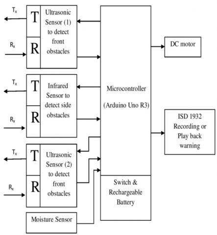
The embedded system designs intelligent techniques to manage power consumption. In ordinary embedded system microprocessors uses external chips for memory and peripheral interface circuit where as in modern embedded system, special microcontroller having storage capacities are used. The processors could be general purpose for certain class of computation or it could be special purpose which is customized for some specific task. So Digital Signal Processor or DSP help to standardize the processors. The heavy production of those embedded systems brings an economical growth whereas the system engineers could design embedded system for specific task with reduced size and cost, with improved reliability and performance. The block diagram of the proposed system is given in Figure 2.
Figure 1. Detection of large and small obstacles
Generally, in the SBS is used to detect any type of objects by using the Viola-Jones algorithm. It is highly potent, and it has shown to be particularly useful in real-time face detection. While our algorithm takes an eternity to train, it is extremely fast at detecting objects in real time.
The programme, given an image (the technique works on grayscale images), examines numerous tiny sub-regions in an effort to locate a face. Because an image may have numerous faces of varying sizes, it must examine a wide range of relative positions and proportions. In their method, Viola and Jones used Haar-like features to identify external objects.
Digital images with Haar-like properties are often utilized for object recognition. Some features of the human face are universal, such as the fact that the area around the eyes is always darker than the surrounding pixels and the area around the nose is always lighter. By adding up the values of the pixels in both regions and comparing the results, we can easily determine which zone is lighter or darker. The total pixel value in the darker area will be less than the total pixel value in the brighter area. If one side is brighter than the other, it could be the outer edge of an eyebrow, and if the center is glossier than the sides, it could be a nose. To do this, we can use features inspired by the work of Haar to decipher the various facial aspects.
Figure 2. Block diagram of proposed system
3.2 Component description
a) Ultrasonic Sensor: Itis used to detect obstacles within a set threshold limit and alert the person through beep speech through speaker if any obstacle detected within that range [34]. The sensor provides a variety of sound pattern and speech to identify different types of obstacles and different directions (Top, Middle, Pit and Water). The ultrasonic sensor emits sound scopes which is inaudible to human ears with frequency lying in ultrasonic spectrum (>20kHz). The sound waves are used to detect the nearby obstacles and the detector is used to detect the reflected sound waves through the help of ultrasonic sensors.
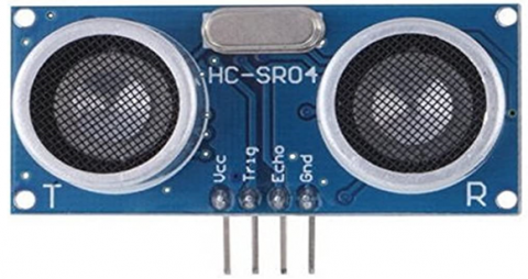
The sound waves that have the frequencies above the human hearing are considered as the ultrasonic waves [35]. We come across a number of applications like detectors to measure proximity, movements, level of liquids etc. which are being used to produce, detect, process and execute the ultrasonic signals. Ultrasonic Ranging Module HC - SR04 is used for detecting the obstacles found in the front of the person and the distance has the range from 2cm to 400cm, that is depcited in Figure 3.
HC-SR04 consist of
There are two opening –
i. Transmitter: The device that is used for signal transmission from source to destination.
ii. Receiver: The device is used to receive the reflected signals that were sent as a high frequency ultrasound waves by the sender or transmitter.
Figure 3. Ultrasonic sensor for SBS
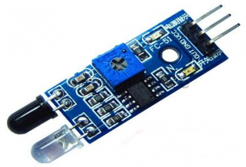
b) Infrared Sensor: Only front obstacle detection is not enough so obstacles on the sides are detected through IR sensors, that shows in Figure 4. Firstly, the obstacles are detected and the data is forwarded for calculation according to the formula: us/58=centimetres or uS/148=inch. The condition and direction of the obstacles are checked through this calculation.
Figure 4. Infrared sensor for SBS
This device has the capacity to detect any obstacle found nearby within a range of 700nm to 1mm. The output totally depends on the type of infrared rays received by the IR sensors. Output provide for comparative circuit as the variation cannot be analysed. But we may have two predictions:
c) Arduino UNO R3: This device is used to alert by operating the buzzer through sending signal after detecting the distance of obstacle. It instructs the buzzer to beep for one time which indicates obstacle on the left side, two times if obstacles are found on the front side and three times if the obstacles are found on the right side [36]. The vibration alert is also facilitated through vibrator connected parallel along with the buzzer for vibration sensation.
Arduino UNO is a motherboard or we can say it is a microcontroller which works with the concepts and technologies of ATmega328. It consists of 20 pins out of which there are about 16 digital pins responsible for input and output operations, 6 analog pins which are responsible for taking the inputs [37]. This motherboard also contains power jack combined with Quartz crystal technology of about 16MHz. The microcontroller is also facilitated with Reset buttons along with ICSP header. Arduino UNO R3 proves very user friendly to work with which is shown in Figure 5.
We can connect this microcontroller either directly with the computer USB cable or AC-DC adapter or battery with 5V operational voltage.
Figure 5. Arduino UNO R3 for SBS
Features of Arduino UNO:
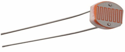
d) Light sensor: This device is used to alert about the darkness or brightness of a place to the blind person, that is depcited in Figure 6. Also helps to detect whether it is night or day [38].
Figure 6. Light sensor for SBS
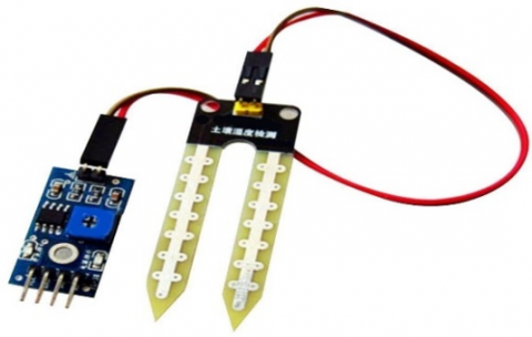
e) Moisture sensor: It is used as a part of the device used to detect if there is any water pits or water puddles, that is shown in Figure 7. If any obstacle found the sensor sends the signal to microcontroller and it sends signal to buzzer to alert the person through sound [39].
Figure 7. Moisture sensor for SBS
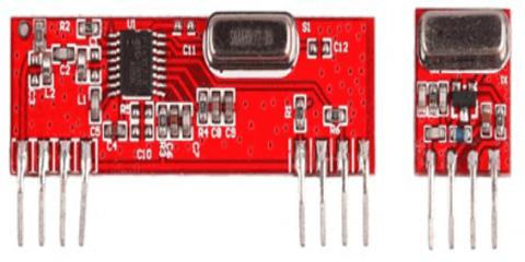
Figure 8. RF transmiter and receiver for SBS
Figure 9. Water sensor for SBS
f) RF transmitter and receiver: 433 MHz RF transmitter and receiver modules are considered as RF Modules, that depcits in Figure 8. In order to transfer the data between two microcontrollers, we require transmitter and receiver [40]. There is no power consumption by the transmitter during logic zero which in turn reduces the transmission of the carrier frequencies which lowers the power consumption impact on the batteries. So when there is any requirement of transmission, the logic zero changes to one where the carrier frequency operates with a power supply of 3V along with 4.5mA. Serial transmission method is used to transmit the data from sender to receiver [41, 42].
g) Water sensor (Robodo REL_35): To see the presence of water and sound an alarm to inform the visually impaired, water detectors are electrical devices that detect the presence of water, that depcits in Figure 9. Liquid leaks, precipitation, water levels, and other types of water can all be monitored [43]. A leak, spill, flood, or rain may be detected by an Arduino-connected water sensor.
Table 2. General characteristics of different sensors
|
Role |
Laser |
Infrared |
Radar |
Ultrasound |
|
Propose |
Light Wave-transmission and reception |
IR pulse light- transmission and reception |
Microwave- transmission and reception |
Acoustic wave- transmission and reception |
|
Beam Width |
Narrow |
Thin |
Depends on Antenna Size |
Wide |
|
charges |
Highest |
Lowest |
Higher |
Lowest |
|
Range |
LLR-10-50m approx. LSR-15-120cm approx. |
20-150cm Approx. |
150-200m approx. |
3cm-10m approx. |
|
Atmospheric Condition |
Can be Affected |
Can be Affected |
Can be Affected |
Cannot be Affected |
In Table 2, the general characteristics of several sensors are shown.
The working behind the smart blind stick (SBS) serves a unique function as a sensing device for the visually impaired. The circuit's output from the power source remains constant at 5V thanks to the circuit's implementation of a voltage regulator. Its ultrasonic sensor and infrared sensor find widespread application for object detection. The ultrasonic sensor alerts the arduino UNO of the presence of any obstacles by reporting their measured distance from the user. The time it takes to send a signal and get it back can be used to estimate how far away an item is. Object Recognition Viola Jones Algorithms is provided to detect object for Mark less Augmentation using Haar Training deals. The algorithm helps to understand the system of the stick and guides to set up its working to the users of respective devices. There is also a facility of device camera for real-time object detection and recognition. Haar training on the objects as well as the port images creates a file for detection of the objects through Haar cascade classifiers.
We can take the help of Viola Jones Algorithms for quickest object detection methods in order to get two important ways to work.
Algorithm 1: Advance SBS distance calculation
Steps:
1. Initialize Blind Stick Location $\left(S_0^T\right)$;
2. Collecting the measurement data queue:
$\left\{D_1^0, D_2^0, D_3^0, D_4^0\right\}$
3. Applying filter (Static):
$\left\{D_1^0, D_2^0, D_3^0, D_4^0\right\}=$ filter $\left(D_1^0, D_2^0, D_3^0, D_4^0\right)$
4. Estimating the location of the obstacle:
L0=LLocate $\left(D_{1 x}^0, D_{3 y}^0\right)$
5. Specifying the Coordinate:
$L_0^T=$ Blind Stick $\left(\mathrm{L}_0, S_0^T\right)$
6. Table for weight relationship:
<L, P >=< $L_0^T$ >, 1 >
7. 7 for k = 1 to K
8. Acquiring Blind Stick location $\left(S_k^T\right)$;
9. Collecting the array of data measured
$\left\{D_1^k, D_2^k, D_3^k, D_4^k\right\}$;
10. Filtering the data in static way:
$\left\{D_1^k, D_2^k, D_3^k, D_4^k\right\}=\operatorname{filter}\left(D_1^k, D_2^k, D_3^k, D_4^k\right)$
11. Advance filtering
$\left\{D_1^{k^{\prime}}, D_2^{k^{\prime}}\right\}=\operatorname{Afilter}\left(D_1^{k-1^{\prime}}, D_2^{k-1^{\prime}}, D_1^{k^{\prime}}, D_2^{k^{\prime}}, S_k^T\right)$
$\left\{D_3^{k^{\prime}}, D_4^{k^{\prime}}\right\}=\operatorname{Afilter}\left(D_3^{k-1^{\prime}}, D_4^{k-1^{\prime}}, D_3^{k^{\prime}}, D_4^{k^{\prime}}, S_k^T\right)$
12. Estimating the location of the obstacle
Lk =LLocate ( $D_{1 x}^{k^{\prime}}, D_{3 y}^{k^{\prime}}$);
13. Specifying the Coordinate:
$L_k^T$= Blind Stick(Lk , $S_k^T$)
14. $\operatorname{if}\left(L_k^T=\mathrm{L}_{\mathrm{x}}\right) \mathrm{P}_{\mathrm{x}}=\mathrm{P}_{\mathrm{x}}+1$;
15. if $\left(\left\|L_k^T-S_k^T\right\|<\mathrm{M}\right)$ then delete $L_k^T$;
16. else <L, P>=<L, P> + <$L_k^T$, 1>
17. end if
18. end if
19. if (Px > W) output $L_x^T$ 20 return
a) In the first method, we can take the help of 45 degree rotated features which proves very efficient in this field and this method is added to the complete set of Haar like feature, and after implementing both these methods it becomes easier to understand the additional domain knowledge while learning framework. The implementation of these two methods can be easily adopted at every scale at constant time.
b) In the second method, in order to improve the performance of the system, an innovative post optimization is used for any given improved classifier. Searching of an image, boosted recognition of objects and many real time applications are applied and implemented through different prototypes. For better portability, Android application is used in this project.
The following are some approaches for measuring distances, which has been described below:
i. Arrival Time / Time of arrival (TOA): The term TOA or Time of Arrival is defined as the ratio between the speed of light as well as carrier frequency of a signal in a single propagation of time which is used to estimate distance between transmitter and receiver. It requires accurate clocks as 1.0µs error which in turn equals to 300m error in distance. Therefore, is becomes impossible for the normal devices in order to entertain TOA for resolving actual distance measuring problems because accurate clocks are expensive.
ii. Arrival Angle / Angle of arrival (AOA): This term is used for triangulation localization method5 as prior knowledge. BLE is not fit to measure angle in normal devices.
iii. Ultrasound: The distance of any node can be measured or calculated easily if we will be able to explore the propagation time of ultrasonic signal from an ultrasonic device. As power of transmission of the ultrasound signal is comparatively weak so there is a chance of that the signal cannot be propagated much further as compared to radio frequency. Each device becomes more in size, cost and energy after adding ultrasound based localization approach. Because of this reason, although having high accuracy, IoT environments are not suitable.
In Wireless Sensor Network (WSN), there is a very popular distance estimation method named as Received Signal Strength (RSS), where value of signal can be easily captured by cell phones without any extra devices. Generally, IEEE 802.11 standards or we can also consider IEEE 802.15.4 standards that are assumed to be followed by Wireless Sensor Nodes.
This paper discusses about the “log-distance path loss model” which can be encountered whenever there will be radio signal propagation by space. Now if we consider the loss of a signal path anywhere enclosed within a building or a messy overcrowded objects by distances then they can be easily measured or estimated through path loss model which can be notified as-
$\mathrm{DL}=\mathrm{D}_{\mathrm{T}}-\mathrm{D}_{\mathrm{R}}=\mathrm{DLS}_{\mathrm{S}}+10 * \mu * \log \left(\mathrm{d}_1 / \mathrm{d}_0\right)+\mathrm{f}$ (1)
where,
DL - measured in decibel as it is the strength of the signal calculated after the total loss of path over distance ‘d1’.
DR - considered as power received.
DT- considered as power transmitted.
DLS - measured in decibel as it is the strength of the signal calculated after the loss of path at distance’d0’.
d1 - considered as path length.
d0 - considered as reference distance.
$\mu$ - considered as the constant or value observed during path loss.
F - Considered a random variable having mean zero which indicates the loss of energy observed by flat fading.
Now if we will consider the specification of iBeacon, the predefined BLE protocols should append power px by the manufacturer. Then we can calculate the value of px power by taking 1 meter as distance. After successful calculation of the power px, some variables can be replaced as per the requirement. Lastly, the receiver can set the power px after receiving the signal as per the following-
d0 - set at a distance of 1 meter,
DLS to DT – set to power px
Therefore, we can set the expression as:
$\mathrm{DL}=\mathrm{D}_{\mathrm{T}}-\mathrm{D}_{\mathrm{R}}=\mathrm{D}_{\mathrm{T}}-\operatorname{power}\left(\mathrm{p}_{\mathrm{x}}\right)+10 * \mu * \log \left(\mathrm{d}_1\right)+\mathrm{f}$ (2)
$D_R=\operatorname{power}\left(p_x\right)-10 * \mu * \log \left(d_1\right)-f$ (3)
By taking the help of empirical measurements we can easily calculate the value of $\mu$ and f, in order to calculate the indoor environments distances, the following coefficients of Android beacon library can be used which can be denoted by the following equation-
d1= (0.89976) * (DR/ power px) 7.7095+0.111 (4)
where, DR and power px are now considered as the two derived variables. Due to fluctuation in the signal strength, the distance that has been calculated gets directly affected and so the manufacturer fixes the value of power px. And now if we will implement some of the filtering algorithms then also it becomes too hard to examine the exact distance which is depcited in Algorithm 1.
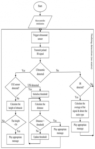
The complete flowchart of the proposed system is explained in Figure 10.
Figure 10. Flowchart for proposed system
Different sensors like Ultrasonic sensors or infrared sensors or PIC18F46K80 model or ISD1932 model sensors are tested individually as well as installed together. Studies of ‘ultrasonic sensors' and its reflections on different obstacles are very important, since ultrasonic sensors operate on the echo principle. To start the measurement process, the microcontroller sends a pulse of around 10µs which is considered as very high level pulse to the pin(T1) triggering the sensor. After receiving the pulse, an ultrasonic signal of around 40 KHz and 450µs (T2) is sent by the sensor and then it will wait to record the output of rising edge through the port (T3) ranging from around 150µs to 25ms and it totally depends on the distance being measured by the sensors. During the absence of obstacles (no reflected signal), it waits for around 38 milliseconds approximately before starting transmission again.
Ultrasonic distance sensors detect obstacles based on the concept of TOF popularly known as Time of Flight - the result is a pulse that in two experiments has been conducted using different obstacles and decides how long it takes to travel from the source to the destination which is depicted in Figure 11.
(a)
(b)
Figure 11. Implementation of Smart Blind Stick (SBS)
After testing the performance of different ultrasonic sensors in the lab, the results were compared with different simulation evaluations and calculations. This comparison shows the difference between the calculation value and the measurement value of an ultrasonic sensor's analog voltage. After that the error value that is calculated is as follows:
For Small range (5.5cm) - 1mV to 6mV.
For Medium range (75.2cm) - 9mV to 23mV.
For high range (250cm-400cm) - 30mV to 47mV.
In order to test the efficiency of the smart stick, we have done experiment in real world by taking the real blind people anonymously. In the first round we have taken various numbers of obstacles and we carried out around two experiments. In this experiment, we took around six blind people to test on the use of smart stick out of which we have taken two trained blind people and four untrained blind people. So, in order to make the experiment more effective, we have taken a testing area where we have taken various obstacles of different sizes and then we allowed a blind person to walk through it. This experiment carried out by involving two trained blind people on smart stick and four non trained blind people. Through experiment the walking speed of the user is recorded. Training and untrained participants are measured by the time they take to successfully walk through obstacles.
Taking into consideration of the above calculations, we observed that the trained people average travelling speed is about 0.81 m/s and the untrained people average speed of travelling is about 0.40 m/s and comparing the value with the sighted people average travelling speed is about 1.5m/s.
Using this method, it was shown that the training resulted in twice as much travel speed as well as increased user confidence in avoiding obstacles. Comparisons should be made with available and current technology. As part of evaluating the performance of a proposed guidance system, a number of factors should be considered, such as detecting the range, time consumed to respond the objects and consumption of power.
Detecting the range is considered as the first parameter. An obstacle-finding device that can cover obstacles between 0 and $2 \mathrm{~m}$ is considered low range, between 2 to $4 \mathrm{~m}$ is considered medium range, and while above $4 \mathrm{~m}$ is considered high range. If we will consider the second parameter then we will observe the response time that a sensor takes to respond as per the following:
The consumption of power is considered as the third parameter and it will reflect the amount of time the system will work by the help of battery or without direct current or recharge. The following power consumption are taken into consideration:
The comparison of the working potential and the result gained of ultrasonic sensors are mentioned in Table 3. The proposed model is giving better object detections in both indoor and outdoor, that is tested in various range of distance (cm). So that, this approach shows best performance that various traditional models, which is depicted in Table 1.
Table 3. Comparison result of ultrasonic sensors
|
Distance in cm |
Calculated Analog Value in mV |
Measured Analog Value in mV |
Error Occurred |
|
5 |
25 |
24.1 |
0.9mv |
|
10 |
50 |
48.6 |
1.4mv |
|
20 |
100 |
97.5 |
2.5mv |
|
30 |
150 |
146.3 |
3.7mv |
|
40 |
200 |
195.4 |
4.6mv |
|
50 |
250 |
244.15 |
5.85mv |
|
70 |
370 |
363.7 |
6.3mv |
|
100 |
500 |
489.4 |
10.6mv |
|
200 |
1000 |
976.8 |
23.2mv |
|
300 |
1500 |
1463.8 |
36.2mv |
|
400 |
2000 |
1954.7 |
45.3mv |
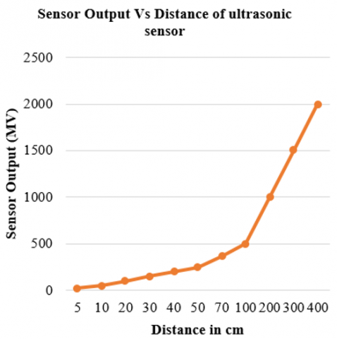
The calculated analog values of the sensors are represented in the graph in Figure 12 and the comparison of the calculated values and measured values are represented through graph in Figure 13.
Figure 13 shows 1 black line and 1 red line. The black line represents calculated analog values of the sensors and the red line represents measured analog values of the sensors.
Figure 12. Graph to represent actual analog values of the sensors
Figure 13. Graph to represent the comparison between the actual analog values and the measured values of the sensors
5.1 Discussion
In order to be considered portable, the device must be light in weight and easy to wear for an extended period as opposed to being non-portable. According to our results, we performed better than the literature from the past 5 years. Several Ultrasonic Sensors, PIC Microcontroller 16F877A, and Voice Alerts for Visually Impaired Persons would provide a quick response while navigating through the testing area whenever they will come in contact with any type of obstacles approximately within an area of about 70 cm. We will take the help of around three sensors for guiding the visually impaired people through the smart stick.
The device is integrated with 16F877A microcontroller along with speakers and vibrating devices to detect the obstacles or obstructions within a range of 2 meters. Similarly, ultrasonic devices and adjustable belts for blind people consists of five sensors, audio recorder of APR9600 model and secondary memory for audio playback devices along with the earphone fitted to the AT89S52 model microcontroller.
This research provides a robust method for detecting the large and small obstacles along with the state of the obstacle i.e. whether the obstacle is in solid or liquid state so that it could help the visually impaired people to move freely when implemented on the blind stick. Generally the accurate distance calculation of the sensors is a big issue but here in this research, we have implemented some more mathematical methods which will definitely bring a new move towards an enhanced smart blind stick. The device is equipped with different sensors like ultrasonic sensors and infrared sensors at different places on the stick in order to get the exact distance and inform it to the visually impaired person through different sounds which then lets the person to move accordingly.
The ultrasonic sensors are used to calculate distant objects along with the size of the objects and the infrared sensors are used to detect very nearby objects like ladders. So the combination of all the sensors along with the microcontrollers and some distance calculation mechanisms we can develop a smart blind stick with accurate distance calculation.
[1] Khan, A., Khusro, S. (2020). An insight into smartphone-based assistive solutions for visually impaired and blind people: Issues, challenges and opportunities. Universal Access in the Information Society, 20: 265-298. https://doi.org/10.1007/s10209-020-00733-8
[2] Cheraghi, S.A., Namboodiri, V., Walker, L., (2017). GuideBeacon: Beacon-based indoor wayfinding for the blind, visually impaired, and disoriented. In 2017 IEEE International Conference on Pervasive Computing and Communications (PerCom), IEEE, Kona, HI, USA, pp. 121-130. https://doi.org/10.1109/PERCOM.2017.7917858
[3] Sharma, H., Tripathi, M., Kumar, A., Gaur, M.S. (2018). Embedded assistive stick for visually impaired persons. In 2018 9th International Conference on Computing, Communication and Networking Technologies (ICCCNT), Bengaluru, India, pp. 1-6. IEEE. https://doi.org/10.1109/ICCCNT.2018.8493707
[4] Shandu, N.E., Owolawi, P.A., Mapayi, T., Odeyemi, K. (2020). AI based pilot system for visually impaired people. In 2020 International Conference on Artificial Intelligence, Big Data, Computing and Data Communication Systems (icABCD), Durban, South Africa, pp. 1-7. https://doi.org/10.1109/icABCD49160.2020.9183857
[5] Yusof, Z.M., Billah, M.M., Kadir, K., Rohim, M.A.S.B., Nasir, H., Izani, M., Razak, A. (2018). Design and analysis of a smart blind stick for visual impairment. Indonesian Journal of Electrical Engineering and Computer Science, 11(3): 848-856. http://dx.doi.org/10.11591/ijeecs.v11.i3.pp848-856
[6] Swain, K.B., Patnaik, R.K., Pal, S., Rajeswari, R., Mishra, A., Dash, C. (2017). Arduino based automated stick guide for a visually impaired person. In 2017 IEEE International Conference on Smart Technologies and Management for Computing, Communication, Controls, Energy and Materials (ICSTM), Chennai, India, pp. 407-410. https://doi.org/10.1109/ICSTM.2017.8089194
[7] Biswal, A.K., Singh, D., Pattanayak, B.K. (2021). IoT-based voice-controlled energy-efficient intelligent traffic and street light monitoring system. In Green Technology for Smart City and Society, pp. 43-54. http://dx.doi.org/10.1007/978-981-15-8218-9_4
[8] Biswal, A.K., Singh, D., Pattanayak, B.K., Samanta, D., Yang, M.H. (2021). IoT-based smart alert system for drowsy driver detection. Wireless Communications and Mobile Computing, 2021: 6627217. https://doi.org/10.1155/2021/6627217
[9] Bhanipati, J., Singh, D., Biswal, A.K. Rout, S.K. (2021). Minimization of collision through retransmission and optimal power allocation in wireless sensor networks (WSNs). In Advances in Intelligent Computing and Communication, pp. 653-665. https://doi.org/10.1007/978-981-16-0695-3_61
[10] Ikbal, M.A., Rahman, F. and Kabir, M.H. (2018). Microcontroller based smart walking stick for visually impaired people. In 2018 4th International Conference on Electrical Engineering and Information & Communication Technology (iCEEiCT), Dhaka, Bangladesh, pp. 255-259. https://doi.org/10.1109/CEEICT.2018.8628048
[11] Chang, W.J., Chen, L.B., Chen, M.C., Su, J.P., Sie, C.Y., Yang, C.H. (2020). Design and implementation of an intelligent assistive system for visually impaired people for aerial obstacle avoidance and fall detection. IEEE Sensors Journal, 20(17): 10199-10210. https://doi.org/10.1109/JSEN.2020.2990609
[12] Kunta, V., Tuniki, C., Sairam, U. (2020). Multi-functional blind stick for visually impaired people. In 2020 5th International Conference on Communication and Electronics Systems (ICCES), Coimbatore, India, pp. 895-899. https://doi.org/10.1109/ICCES48766.2020.9137870
[13] Chatterjee, S., Kar, A.K., Gupta, M.P. (2018). Success of IoT in smart cities of India: An empirical analysis. Government Information Quarterly, 35(3): 349-361. https://doi.org/10.1016/j.giq.2018.05.002
[14] Zhao, L., Wang, J., Liu, J., Kato, N. (2019). Optimal edge resource allocation in IoT-based smart cities. IEEE Network, 33(2): 30-35. https://doi.org/10.1109/MNET.2019.1800221
[15] Subbiah, S., Ramya, S., Krishna, G.P., Nayagam, S. (2019). Smart cane for visually impaired based on IoT. In 2019 3rd International Conference on Computing and Communications Technologies (ICCCT), Chennai, India, pp. 50-53. https://doi.org/10.1109/ICCCT2.2019.8824893
[16] Ramadhan, A.J. (2018). Wearable smart system for visually impaired people. Sensors, 18(3): 843. http://dx.doi.org/10.3390/s18030843
[17] Budilaksono, S., Bertino, B., Suwartane, I.G.A., Rosadi, A., Suwarno, M.A., Purtiningrum, S.W., Sari, Y., Suhandono, E., Sakti, E.M.S., Gustina, D., Riyadi, A.A. (2020). Designing an ultrasonic sensor stick prototype for blind people. Journal of Physics: Conference Series, 1471(1): 012020. http://dx.doi.org/10.1088/1742-6596/1471/1/012020
[18] Zaidan, A.A., Zaidan, B.B., Qahtan, M.Y., Albahri, O.S., Albahri, A.S., Alaa, M., Jumaah, F.M., Talal, M., Tan, K.L., Shir, W.L., Lim, C.K. (2018). A survey on communication components for IoT-based technologies in smart homes. Telecommunication Systems, 69(1): 1-25. https://doi.org/10.1007/s11235-018-0430-8
[19] Wan, J., Al-awlaqi, M.A., Li, M., O’Grady, M., Gu, X., Wang, J., Cao, N. (2018). Wearable IoT enabled real-time health monitoring system. EURASIP Journal on Wireless Communications and Networking, 2018(1): 298. https://doi.org/10.1186/s13638-018-1308-x
[20] Manogaran, G., Shakeel, P.M., Fouad, H., Nam, Y., Baskar, S., Chilamkurti, N. and Sundarasekar, R. (2019). Wearable IoT smart-log patch: An edge computing-based Bayesian deep learning network system for multi access physical monitoring system. Sensors, 19(13): 3030. https://doi.org/10.3390/s19133030
[21] Huifeng, W., Kadry, S.N. and Raj, E.D. (2020). Continuous health monitoring of sportsperson using IoT devices based wearable technology. Computer Communications, 160: 588-595. https://doi.org/10.1016/j.comcom.2020.04.025
[22] Kumar, P.M., Gandhi, U., Varatharajan, R., Manogaran, G., Jidhesh, R., Vadivel, T. (2019). Intelligent face recognition and navigation system using neural learning for smart security in Internet of Things. Cluster Computing, 22(4): 7733-7744. https://doi.org/10.1007/s10586-017-1323-4
[23] Rahman, M.M., Islam, M.M., Ahmmed, S., Khan, S.A. (2020). Obstacle and fall detection to guide the visually impaired people with real time monitoring. SN Computer Science, 1: 219. https://doi.org/10.1007/s42979-020-00231-x
[24] Pathak, A., Adil, M., Rafa, T.S., Ferdoush, J., Mahmud, A. (2020). An IoT based voice controlled blind stick to guide blind people. International Journal of Engineering Inventions, 9(1): 9-14.
[25] Arora, A., Grover, A., Chugh, R., Reka, S.S. (2019). Real time multi object detection for blind using single shot multibox detector. Wireless Personal Communications, 107: 651-661. https://doi.org/10.1007/s11277-019-06294-1
[26] Asati, C., Meena, N., Orlando, M.F. (2019). Development of an intelligent cane for visually impaired human subjects. In 2019 28th IEEE International Conference on Robot and Human Interactive Communication (RO-MAN), New Delhi, India, pp. 1-5. https://doi.org/10.1109/RO-MAN46459.2019.8956328
[27] Bashiri, F.S., LaRose, E., Badger, J.C., D’Souza, R.M., Yu, Z., Peissig, P. (2018). Object detection to assist visually impaired people: A deep neural network adventure. In Advances in Visual Computing: 13th International Symposium, ISVC 2018, Las Vegas, NV, USA, pp. 500-510. https://doi.org/10.1007/978-3-030-03801-4_44
[28] Bhandari, A., Prasad, P.W.C., Alsadoon, A., Maag, A. (2021). Object detection and recognition: Using deep learning to assist the visually impaired. Disability and Rehabilitation: Assistive Technology, 16(3): 280-288. https://doi.org/10.1080/17483107.2019.1673834
[29] Chen, L.B., Su, J.P., Chen, M.C., Chang, W.J., Yang, C.H., Sie, C.Y. (2019). An implementation of an intelligent assistance system for visually impaired/blind people. In 2019 IEEE International Conference on Consumer Electronics (ICCE), Las Vegas, NV, USA, pp. 1-2. https://doi.org/10.1109/ICCE.2019.8661943
[30] Felix, S.M., Kumar, S., Veeramuthu, A. (2018). A smart personal AI assistant for visually impaired people. In 2018 2nd international conference on trends in electronics and informatics (ICOEI), Tirunelveli, India, pp. 1245-1250. https://doi.org/10.1109/ICOEI.2018.8553750
[31] Jain, B.D., Thakur, S.M., Suresh, K.V. (2018). Visual assistance for blind using image processing. In 2018 International Conference on Communication and Signal Processing (ICCSP), pp. 0499-0503. http://dx.doi.org/10.1109/ICCSP.2018.8524251
[32] Mule, N., Patil, D.D., Chavhan, Y.D. (2020). In-house object detection system for visually impaired. International Journal of Future Generation Communication and Networking, 13(4): 4919-4926.
[33] Johari, R., Gaurav, N.K., Chaudhary, S., Pramanik, A. (2020). START: Smart stick based on TLC algorithm in IoT network for visually challenged persons. In 2020 Fourth International Conference on I-SMAC (IoT in Social, Mobile, Analytics and Cloud) (I-SMAC), Palladam, India, pp. 605-610. https://doi.org/10.1109/I-SMAC49090.2020.9243517
[34] Ray, P.P., Thapa, N., Dash, D., De, D. (2019). Novel implementation of IoT based non-invasive sensor system for real-time monitoring of intravenous fluid level for assistive e-healthcare. Circuit World. https://doi.org/10.1108/CW-01-2019-0008
[35] Mothe, R., Reddy, S.T., Sunil, G., Sidhardha, C. (2020). An IoT based obstacle avoidance robot using ultrasonic sensor and Arduino. In IOP Conference Series: Materials Science and Engineering, 981(4): 042002. https://doi.org/10.1088/1757-899X/981/4/042002
[36] Karthik, B.N., Parameswari, L.D., Harshini, R., Akshaya, A. (2018). Survey on IoT & Arduino based patient health monitoring system. International Journal of Scientific Research in Computer Science, Engineering and Information Technology, 3(1): 1414-1417.
[37] Panchatcharam, P., Vivekanandan, S. (2019). Internet of Things (IoT) in healthcare–smart health and surveillance, architectures, security analysis and data transfer: A review. International Journal of Software Innovation (IJSI), 7(2): 21-40. http://dx.doi.org/10.4018/978-1-6684-6311-6.ch007
[38] Demircilioğlu, E., Teomete, E., Schlangen, E., Baeza, F.J. (2019). Temperature and moisture effects on electrical resistance and strain sensitivity of smart concrete. Construction and Building Materials, 224: 420-427. https://doi.org/10.1016/j.conbuildmat.2019.07.091
[39] Biswal, A.K., Samantaray, M. (2020). A novel approach for localization in sensor network. International Journal of Engineering Research & Technology (IJERT), 9(1): 323-328. http://dx.doi.org/10.17577/IJERTV9IS010195
[40] Sundaravadivel, P., Kougianos, E., Mohanty, S.P., Ganapathiraju, M.K. (2017). Everything you wanted to know about smart health care: Evaluating the different technologies and components of the internet of things for better health. IEEE Consumer Electronics Magazine, 7(1): 18-28. https://doi.org/10.1109/MCE.2017.2755378
[41] Biswal, A. K., Singh, D., Pattanayak, B. K., Samanta, D., Chaudhry, S. A., Irshad, A. (2021). Adaptive fault-tolerant system and optimal power allocation for smart vehicles in smart cities using controller area network. Security and Communication Networks, 2021(7). http://dx.doi.org/10.1155/2021/2147958
[42] Singh, D., Biswal, A.K., Samanta, D., Singh, D., Lee, H.N. (2022). Juice jacking: Security issues and improvements in USB technology. Sustainability, 14(2): 939. https://doi.org/10.3390/su14020939
[43] Biswal, A.K., Singh, D., Tripathy, A.K., Pattanayak, B. K. (2022). Smart Autonomous Collision Avoidance and Obstacle Detection Using Internet of Things (IoT) and Controller Area Network (CAN) Protocol. In Advances in Distributed Computing and Machine Learning, pp. 54-65. Springer, Singapore. http://dx.doi.org/10.1007/978-981-16-4807-6_6