
Ali A. Sultan | Mohammed A. Mashrei* | Raed Abdul Hassan Ali
© 2026 The authors. This article is published by IIETA and is licensed under the CC BY 4.0 license (http://creativecommons.org/licenses/by/4.0/).
OPEN ACCESS
While individual anchoring techniques such as carbon fiber reinforced polymer (CFRP) spike anchors and surface grooving have been proven to be effective, the synergistic efficacy of combining these systems with different configurations remains underexplored. This study experimentally investigates a hybrid anchorage system integrating surface grooving with carbon fiber spike anchors (CFSA). Eight RC beams were evaluated, including a control beam (CB), a conventional EB-CFRP beam, and specimens strengthened with an individual anchorage system. The remaining specimens investigated hybrid anchoring systems: one pairing full-length grooving with a single spike anchor (SA), and three examining reduced grooving lengths (by 20% and 40%) across varying spike anchor intensities, all incorporating a single intermediate U-wrap. All anchoring configurations enhanced the flexural strength and stiffness of the beams; however, these gains were accompanied by a reduction in ductility. Despite shorter grooving lengths, specimens utilizing spike anchors combined with intermediate U-wrapping exhibited superior flexural strength. Specifically, configurations featuring 600 mm grooving with double end-anchors and 800 mm grooving with single end-anchors increased ultimate loads by over 89% and 96% compared to the CB, outperforming the externally bonded reinforcement (EBR) system by approximately 54% and 59%, respectively. The transition from premature CFRP debonding to material rupture demonstrates the efficacy of the proposed anchoring techniques.
carbon fiber, carbon fiber spike anchors, delamination, grooving, flexural, U-wrapping
Reinforced concrete (RC) structures frequently require rehabilitation, retrofitting, or strengthening due to material aging, functional obsolescence, or changes in design requirements. Due to the high strength-to-weight ratio and durability characteristics of carbon fiber reinforced polymer (CFRP), such materials are currently preferred for such applications [1]. CFRP has recently emerged as a primary solution in structural strengthening applications compared to the traditional counterpart materials [2-6]. However, the problem of CFRP delamination from the substrate surface in regions of high shear and flexural stresses is the main limitation of utilizing the full capacity of CFRP strengthening [7-9]. Without proper incorporation of some confinement or anchorage systems, CFRP materials can only utilize 10–25% [7], or at best estimate only 50% of its strength [10].
In an effort to utilize the full tensile capacity of CFRP material by increasing the bonding strength, several confinement and anchoring techniques have been proposed and individually verified during the last few decades. As shown in Figure 1, carbon fiber jacketing (also known as U-Wrapping) and fiber-reinforced polymer (FRP) near-surface mounted (NSM) are among the most recognized solutions [2, 5, 8, 11-16]. It has been reported that such confinement systems can significantly improve the strength, ductility, stiffness, and overall performance of strengthened elements [6, 9, 11, 17]. However, each technique has its own drawbacks and limitations. For example, by implementing U-wrapping alone, debonding at the concrete-FRP interface near the termination point of the “U-anchors” is frequently reported as the dominant failure mode, unless mechanically anchored [18, 19]. NSM, on the other hand, requires deep grooves (typically in Figure 1, hg = 15–30 mm deep [14]) to completely submerge a rigid FRP bar or strip. If the existing concrete cover is thin, this technique is practically disqualified because structural stirrups or tension steel might be cut due to the grooving process.
During the past few years, some researchers proposed geometric modification of the substrate surface by introducing shallow surface grooves to increase the bond area between CFRP and the substrate concrete, as shown in Figure 2 [20-24]. Introducing externally bonded fiber-reinforced polymer (EB-FRP) on/in grooves (externally bonded reinforcement on grooves (EBROG)/externally bonded reinforcement in grooves (EBRIG)) has resulted in a significant improvement in the flexural performance of strengthened RC elements due to the enhancement in the bond strength between the strengthening and substrate materials [21, 25, 26]. While grooving configurations are typically shallow, the technique becomes less viable for extensive surface applications or degraded RC elements. In such cases, the high labor intensity and prolonged installation time considerably reduce the efficacy of grooving techniques relative to alternative retrofitting strategies. In addition, it has been reported that such surface modifications do not completely prevent debonding, but can only postpone such failure due to better utilization of FRP tensile strength [26-28].
It has recently been reported in some relevant publications that carbon fiber spike anchors (CFSA) can be a vital solution to the CFRP delamination problem by providing continuity to the load path and therefore directly transferring stresses to the substrate material [29-33]. The interfacial compatibility between the anchoring and strengthening materials—both being carbon fiber—optimizes the performance of the anchorage through material homogeneity. Furthermore, the implementation of CFSA is non-invasive, preserving the original dimensions, weight, and structural integrity of the strengthened structural elements. Beyond these structural benefits, the installation of CFSA is significantly more efficient than traditional alternatives, offering a rapid and less labor-intensive application.
While significant progress has been made towards understanding FRP-to-concrete bonding, the most recent version of the ACI PRC-440.2-23 design code [34] highlights a persistent need for “additional evidence to validate performance” in several key areas. A primary recommendation from the code involves the exploration of various anchoring configurations as a means to enhance structural integrity. This study responds to that mandate by addressing the ongoing challenges of debonding through the evaluation of hybrid anchorage strategies, an area that the ACI PRC-440.2-23 [34] code explicitly identified as requiring more robust experimental data. Moving beyond the study of individual anchorage methods that have been extensively investigated, this work investigates the combined application of spike anchors and surface grooving. This approach seeks to determine how and to what extent such a hybrid configuration enhances the structural performance indices such as flexural strength, ductility, stiffness, and energy absorption (toughness) of EB-CFRP-strengthened beams compared to traditional single-method benchmarks.
In order to achieve the objectives of the research, a total of eight beam specimens of different grooving and strengthening configurations were fabricated and tested. This section provides information about the used material properties, specimen design, installation of CFRP sheets and anchors, and testing procedures.
2.1 Material used
The cement and aggregates used to produce the concrete had been individually tested and verified according to the relevant international specifications prior to use. Then, a concrete mix of 30 MPa targeted compressive strength was designed and implemented for the entire experimental work; Table 1 shows the concrete mix proportions. To determine the actual compressive strength of the design mix, six standard cubes of 150 × 150 × 150 mm were cast and tested under compression as per BS EN 12390-3 [35]. Three cubes were tested at 7 days, and the other three were tested at 28 days. Results of compressive strengths at 7 and 28 days are provided in Table 2. On the other hand, steel bars of φ8 mm diameter were also tested and verified as per BS 4449-05 [36], as shown in Table 3.
Table 1. Concrete mix (kg/m3)
|
Cement |
Fine Aggregate |
Coarse Aggregate |
Water |
Plasticizer |
|
410 |
738 |
1025 |
170 |
2.0 |
Table 2. The actual compressive strength of the concrete mix used
|
Sample |
7 Days |
28 Days |
|
1 |
19.00 |
32.04 |
|
2 |
19.43 |
31.34 |
|
3 |
19.89 |
29.62 |
|
Mean (MPa) |
19.44 |
31.0 |
Table 3. Properties of steel bars used
|
Diameter (mm) |
Yield Strength, Re (MPa) |
Ultimate Strength, Rm (MPa) |
Elongation (%) |
|
8 |
582 |
658 |
14.5 |
|
BS 4449-05 Limits |
485< Re < 650 |
Rm / Re ≥ 1.06 |
≥4% |
The strengthening of RC beam specimens was carried out using a unidirectional carbon fiber fabric (SikaWrap-230C) in combination with a high-modulus epoxy adhesive (Sikadur-330). The technical properties of both materials are summarized in Table 4.
For the specimens strengthened with spike anchors, the anchors were fabricated using SikaWrap-Fx50C in conjunction with Sikadur-52LP. The technical properties of both materials are presented in Table 5. According to ACI PRC‑440.2‑23 [34], the tensile strength of the anchoring material must be equal to or greater than that of the externally bonded FRP laminate. This requirement ensures that the anchor does not act as a weak link in the system and can reliably transfer stresses into the concrete substrate. Therefore, SikaWrap-Fx50C would be suitable for this purpose as per the manufacturer's recommendations. The materials listed in both Table 4 and Table 5 are shown in Figure 3.
Table 4. Technical properties of SikaWrap-230C and Sikadur-330
|
Material |
Commercial Name |
Technical Property |
Units |
Value |
|
Carbon Fiber Fabric |
SikaWrap-230C |
Thickness |
mm |
0.13 |
|
Weight |
g/m2 |
230 ± 10 |
||
|
Tensile Modulus |
GPa |
238 |
||
|
Elongation at Break |
% |
1.8 |
||
|
Tensile Strength |
MPa |
4300 |
||
|
Paste-Like Epoxy Resin@7 days |
Sikadur-330 |
Tensile Strength |
MPa |
33.8 |
|
Elastic Modulus |
MPa |
3489 |
||
|
Flexural Strength |
MPa |
60.6 |
||
|
Elongation at Break |
% |
1.2 |
Table 5. Technical properties of SikaWrap-Fx50C and Sikadur-52LP
|
Material |
Commercial Name |
Technical Property |
Units |
Value |
|
Unidirectional Cord |
SikaWrap-Fx50C |
Dry Cross-Sectional Area |
mm2 |
28.26 |
|
Impregnated Cross-Sectional Area |
mm2 |
78.00 |
||
|
Dry Tensile Strength |
MPa |
4000 |
||
|
Impregnated Tensile Strength |
MPa |
2000 |
||
|
Dry Modulus of Elasticity |
GPa |
240 |
||
|
Impregnated Modulus of Elasticity |
GPa |
230 |
||
|
Low-Viscosity Resin@7 days, 30 ℃ |
Sikadur-52LP |
Compressive Strength |
MPa |
≥70.0 |
|
Tensile Strength |
MPa |
≥27.0 |
||
|
Tensile Adhesion Strength
|
MPa MPa |
≥7.0 ≥10.0 |
Figure 3. Strengthening and anchoring materials
2.2 Grooving, strengthening and anchoring process
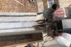
The strengthening process has begun immediately after the end of the concrete curing period of the beam samples. All surfaces that will be utilized for the attachment of strengthening materials have been roughened by using a steel grinder, where a very thin loose layer has been removed. Then, grooving of the samples with grooves has been performed by an electrical handheld concrete saw using a diamond blade with the help of a special moveable steel frame designed specifically for this purpose as shown on Figure 4. The grooving process, as well, has begun at the end of 28 days concrete curing period to avoid any disturbance to beam cover during the critical period of gaining the concrete strength. In each beam with grooving, three longitudinal square grooves of dimensions and spacing between grooves of 6 ± 1 mm and 31 ± 1 mm, respectively, have been introduced in all those specimens.
Drilling the spike anchor holes, on the other hand, began by drilling 90 mm deep holes at the designated locations using a 12 mm diameter steel drill bit. After drilling was completed, the hole surface was roughened and cleaned to ensure no loose particles existed around the edge of the hole. All beams, including those with holes and grooves, were then cleaned thoroughly using a special brush, air pump, and water jetting to maximize the bond quality.
Figure 4. Grooving tool used in the experimental work
The CFRP strengthening procedure began with the uniform application of Sikadur 330 adhesive across the beam soffit. Subsequently, a 100 mm-wide strip of SikaWrap-230C was bonded along the 1000 mm span of the beam. To eliminate entrapped air beneath the carbon fiber layer, a special roller was passed over the bonded sheet, in accordance with manufacturer guidelines and recommendations from previous studies.
For the installation of spike anchors, bundles of SikaWrap-Fx50C with a length of 140 mm were cut, and 80 mm of this length was impregnated with the premixed Sikadur-52LP. This low-viscosity epoxy resin is recommended by the manufacturer of SikaWrap-Fx50C for best impregnation results. The impregnated part was tied at the end with a single plastic tie and left for a few minutes to facilitate the insertion process. The predrilled holes were filled with Sikadur 330 prior to the insertion of spike anchors inside the holes. The remaining 50 mm dry part of the anchor was then splayed over the pre-bonded SikaWrap-230C layer and finished by using the same roller used before to remove any entrapped air beneath the splayed part. The main strengthening steps are shown in Figure 5.
Figure 5. Strengthening process: (a) grooved beams; (b) drilling anchor holes; (c) anchors impregnated with Sikadur-52LP epoxy; (d) tying the impregnated anchors; (e) filling an anchor hole with Sikadur-330 epoxy; (f) inserting a spike anchor inside a prefilled hole; and (g) splaying out the dry end of the spike anchor
2.3 Design of the specimens
The control, as well as the strengthened beam specimens of this experiment, have been designed to fail in flexure considering the potential increase in the flexural capacity due to the strengthening system. The beams were tested up to failure under a four-point loading scheme. Each beam was fabricated with dimensions of bw = 120 mm, h = 170 mm, total length L = 1200 mm, and a clear span S = 1000 mm. Longitudinal reinforcement at the bottom and top fibers of the section consisted of 2φ8 mm rebar each. A dense stirrup spacing of φ8@60 mm distributed along the entire span of the beams was implemented in the experiment, as stated above, to guarantee that flexural failure is the dominant mode of failure for all beam specimens, even for the strengthened beams. Figure 6 shows the geometry and reinforcement details of the tested beams.
Figure 6. Geometry, reinforcement details, and testing setup of the tested beams
Figure 7. Strengthening and anchoring configurations of the tested beams
The control beam (CB) was left without any strengthening or anchoring systems to serve as a reference beam. On the other hand, the specimen with externally bonded reinforcement (EBR) has been conventionally strengthened with a 1000 mm long single bottom EB-FRP layer to determine the possible gain in the flexural capacity due to the conventional strengthening process. As summarized in Table 6, the objectives of testing the other six beam specimens are as follows:
•Respectively, specimens with full-length grooving (FG) and single spike anchor (SA) were tested to investigate the advantages of incorporating a single anchoring system such as longitudinal grooving or spike anchors.
•Specimen FGSA was tested to determine the potential
improvement in the behavior (and therefore flexural strength), compared to FG and SA, when a hybrid anchoring system consisting of longitudinal grooving and spike anchors together is incorporated in the same beam specimen.
•The last three specimens examined the influence of reducing the grooving length while varying the anchorage configuration, with all specimens incorporating a single intermediate U-wrap. Specifically, G6SAU employed a 600 mm grooving length combined with a SA; G6DAU utilized the same 600 mm grooving length but doubled the number of spike anchors. The third specimen, G8SAU, adopted an 800 mm grooving length with a SA. This comparative setup enables assessment of how both the grooving length and the number of spike anchors interact with intermediate U wrapping to affect the overall strengthening performance. Figure 7 shows the strengthening and anchoring configuration details of all tested beams.
It is noteworthy that the incorporation of intermediate U wraps at the midspan of the last three specimens was introduced only after testing the initial five beams, in which the control failure mode was governed by the formation of extensive intermediate cracks. To mitigate the risk of CFRP debonding associated with intermediate flexural cracking and to redirect the higher stress concentrations toward the specimen ends, the intermediate U wrap was implemented as an additional anchorage measure.
2.4 Testing setup
As shown in Figure 6, all beam specimens were supported by two roller supports with a 1000 mm clear span and tested under a four-point loading scheme using a 200 kN testing machine. A very stiff steel spreader beam was utilized to divide the applied load into two equal point loads 340 mm apart (shear span = 330 mm). An electronic dial gauge of 0.01 mm accuracy was used to measure the corresponding midspan deflection as the load was applied. The load was applied gradually at a constant rate of 0.5 kN/s until the failure state was reached. The data required for load-deflection relationships and the associated structural performance indices such as ductility, stiffness, and toughness have been collected with the assistance of high-resolution cameras with slow-motion capability.
Table 6. Strengthening and anchoring configurations of beam specimens
|
Beam Description |
Beam ID |
Length of Grooving (mm) |
No. of “SA” at each end |
Key Points Investigated |
|
Control (non-strengthened) |
CB |
- |
- |
Reference beam |
|
Control with only EB-FRP |
EBR |
- |
- |
Conventional EBR strengthening |
|
EBR with only full-length grooving |
FG |
1000 |
- |
Effect of full grooving |
|
EBR with only single spike anchor at CFRP termination points |
SA |
- |
1 |
Effect of spike anchor |
|
EBR with full-length grooving and a single spike anchor at CFRP termination points |
FGSA |
1000 |
1 |
Effect of combining full grooving and single spike anchor |
|
EBR with 600 mm grooving, a single spike anchor at CFRP termination points and a single 100 mm wide midspan U-Wrap |
G6SAU |
600 |
1 |
Effect of reducing length of grooves to 600 mm with single spike anchor, and an intermediate U-wrap |
|
EBR with 600 mm grooving, a double spike anchor at CFRP termination points and a single 100 mm wide midspan U-Wrap |
G6DAU |
600 |
2 |
Effect of reducing length of grooves to 600 mm, double the number of spike anchors, and an intermediate U-wrap |
|
EBR with 800 mm grooving, a single spike anchor at CFRP termination points and a single 100 mm wide midspan U-Wrap |
G8SAU |
800 |
1 |
Effect of reducing length of grooves to 800 mm with single spike anchor, and an intermediate U-wrap |
3.1 Critical loads and corresponding deflections
The cracking, flexural steel yielding, and ultimate moments during the test, and the corresponding deflections have been carefully recorded. Table 7 shows the recorded loads and deflections of all tested specimens. Depending on the data recorded, the percentage increase/decrease in the recorded critical loads and midspan deflections has been determined as compared to the CB and to the EBR beam as listed in Tables 8 and 9, respectively. In both tables, the positive sign indicates an increase, and the negative sign indicates a decrease in the calculated index.
Examining Tables 8 and 9, it can be concluded that either of the strengthening systems employed has resulted in a marginal positive effect regarding the load-carrying capacity at all critical loading stages.
Table 7. Critical loads and midspan deflections
|
Beam |
Cracking Stage |
Yielding Stage |
Ultimate Stage |
|||
|
Load (kN) |
Deflection (mm) |
Load (kN) |
Deflection (mm) |
Load (kN) |
Deflection (mm) |
|
|
CB |
21 |
3.1 |
51 |
8.2 |
56 |
16.3 |
|
EBR |
30.5 |
3.5 |
64 |
9.0 |
69 |
10.9 |
|
FG |
34 |
3.3 |
90 |
10.8 |
102.5 |
15.4 |
|
SA |
32 |
2.8 |
90.5 |
10.1 |
102 |
13.6 |
|
FGSA |
32 |
3.3 |
99 |
12.9 |
108.5 |
16.1 |
|
G6SAU |
34 |
3.1 |
87 |
9.5 |
96 |
11.5 |
|
G6DAU |
42 |
3.9 |
94 |
10.3 |
106 |
14.1 |
|
G8SAU |
42 |
3.3 |
96 |
9.3 |
110 |
12.7 |
Table 8. Increase/decrease of critical loads and midspan deflections compared to CB
|
Beam |
Cracking Stage |
Yielding Stage |
Ultimate Stage |
|||
|
Load (%) |
Deflection (%) |
Load (%) |
Deflection (%) |
Load (%) |
Deflection (%) |
|
|
CB |
0.00 |
0.00 |
0.00 |
0.00 |
0.00 |
0.00 |
|
EBR |
45.24 |
11.61 |
25.49 |
10.43 |
23.21 |
-33.17 |
|
FG |
61.90 |
6.45 |
76.47 |
32.52 |
83.04 |
-5.51 |
|
SA |
52.38 |
-11.29 |
77.45 |
23.93 |
82.14 |
-16.65 |
|
FGSA |
52.38 |
5.16 |
94.12 |
58.28 |
93.75 |
-1.29 |
|
G6SAU |
61.90 |
0.65 |
70.59 |
16.56 |
71.43 |
-29.38 |
|
G6DAU |
100 |
26.77 |
84.31 |
26.38 |
89.29 |
-13.71 |
|
G8SAU |
100 |
5.16 |
88.24 |
14.11 |
96.43 |
-22.34 |
Table 9. Increase/decrease of critical loads and midspan deflections compared to EBR
|
Beam |
Cracking Stage |
Yielding Stage |
Ultimate Stage |
|||
|
Load (%) |
Deflection (%) |
Load (%) |
Deflection (%) |
Load (%) |
Deflection (%) |
|
|
CB |
-31.15 |
-10.40 |
-20.31 |
-9.44 |
-18.84 |
49.63 |
|
EBR |
0.00 |
0.00 |
0.00 |
0.00 |
0.00 |
0.00 |
|
FG |
11.48 |
-4.62 |
40.63 |
20.00 |
48.55 |
41.39 |
|
SA |
4.92 |
-20.52 |
41.41 |
12.22 |
47.83 |
24.73 |
|
FGSA |
4.92 |
-5.78 |
54.69 |
43.33 |
57.25 |
47.71 |
|
G6SAU |
11.48 |
-9.83 |
35.94 |
5.56 |
39.13 |
5.68 |
|
G6DAU |
37.70 |
13.58 |
46.88 |
14.44 |
53.62 |
29.12 |
|
G8SAU |
37.70 |
-5.78 |
50.00 |
3.33 |
59.42 |
16.21 |
Traditional CFRP strengthening, as in specimen EBR, has resulted in a noticeable increase in the cracking, yielding, and ultimate loads by more than 45, 25, and 23%, respectively, compared to the CB specimen. However, such an increment in the ultimate load-carrying capacity was at the expense of midspan deflection, where the corresponding ultimate deflection has been decreased by 33%, which will ultimately result in a reduced ductility of EBR compared to CB, as will be discussed later.
Specimens FG and SA, where either full grooving or spike anchors, respectively, were incorporated, led to an increase in the critical loads recorded at all loading stages as compared to CB and EBR specimens. For specimen FG, the critical loads, in sequence, have been increased by 62, 76, and 83% compared to CB, and by 11, 41, and 49% compared to the EBR beam. Similarly, specimen SA showed an increase in the load-carrying capacity during the critical loading stages by 52, 77, and 82% compared to CB, and by 5, 41, and 48% compared to the EBR specimen. Both beams, especially the one with FG, have provided a comparable ultimate deflection compared to the CB, where the ultimate deflections have been reduced by about 5.5 and 16.5% for specimens FG and SA, respectively. This probably will result in an enhancement in the beam's ductility compared to the EBR beam, where only externally bonded CFRP has been incorporated.
With respect to the FGSA specimen, which, in addition to the EBR strengthening, has been additionally anchored by means of full-length grooving and an SA at each CFRP layer termination point, it has shown superior behavior and therefore loading capacity compared to either of the specimens discussed above. For example, the ultimate load of this beam has been increased by more than 94 and 57% compared to CB and EBR, respectively. In addition, the difference in the ultimate deflection of this beam specimen was only 1.29% smaller than CB and about 48% larger than the ultimate deflection in comparison with the EBR specimen.
The last three beams that were tested to evaluate the interaction of grooving length and spike anchor quantity with the presence of intermediate U-wrapping also exhibited superior performance compared to the CB and EBR specimens, as shown in Tables 8 and 9. Specifically, the specimen featuring double spike anchors with 600 mm grooving (G6DAU) and the specimen with a SA and 800 mm grooving (G8SAU) achieved yielding and ultimate loads comparable to those of the FGSA. In addition, these specimens nearly doubled the capacity of the CB. This demonstrates that intermediate U-wrapping can successfully compensate for a 40% and 20% reduction in grooving length when utilizing double and single anchors, respectively. The G6SAU specimen likewise demonstrated considerable load-carrying capacity at all three loading stages. Nonetheless, its overall results were marginally lower than the other two specimens in this category. This difference was particularly pronounced in the cracking load, which increased by only 62% compared to the 100% improvement achieved by both G6DAU and G8SAU.
3.2 Modes of failure
Failure of RC beams is not a sudden event at a single load point; it is a gradual process that begins with cracking and evolves through several stages until ultimate collapse. Therefore, failure mode can be considered a critical flexural performance aspect, particularly when CFRP strengthening is employed. CFRP debonding is considered a highly unfavorable failure mechanism because it occurs abruptly and without warning once the ultimate strain capacity of either the CFRP-epoxy or epoxy-concrete interface is reached [4, 6, 37]. The modes of failure of all tested beams, as shown in Figure 8, have been carefully monitored and discussed.
The CB exhibited flexural failure as flexural cracks initiated once the cracking load reached 21 kN. As the applied load increased, these cracks propagated extensively and penetrated deeper into the section. Ultimately, the beam failed when the applied load and corresponding deflection reached 56 kN and 16.34 mm, respectively.
Similarly, the failure process of the EBR specimen also started once the cracking load reached 30.5 kN (about 45% of CB). When the applied load slightly increased, some shear cracks were also initiated. Flexural and shear cracks penetrated deeper into the section, but at a lower rate compared to CB, as the applied load increased up to the sudden failure by end-CFRP debonding, as shown in Figure 8, which is encountered at the ultimate load and corresponding deflection of 69 kN and 10.92 mm, respectively.
The other six beams tested displayed the same failure process as EBR, where flexural and some shear cracks initiated once the applied load reached a specific value ranging from 32 to 42 kN. These cracks have been widening and penetrating deeper into the section, and some other new cracks have been initiated as the applied load increased. Ultimately, either of the beam specimens in this category has failed abruptly once the ultimate load has reached a specific value depending on the strengthening and anchoring configuration employed, as shown in Table 7.
Figure 8. Mode of failure of the tested beams
Except for the FG specimen, which failed due to concrete cover separation, the five specimens reinforced with additional spike anchors exhibited a shift in failure mode from CFRP debonding to CFRP rupture followed by flexural failure. As illustrated in Figure 8, this transition to a more desirable failure mechanism, along with an increased load-carrying capacity, confirms the effectiveness of the spike anchoring technique. From the current results, it can be concluded that the anchored specimens sustained the CFRP contribution to exhibit delayed debonding and higher load levels in comparison with the control specimen. This behavior, combined with the enhanced load-deflection relationship, provides additional evidence of more effective stress transfer provided by the spike anchors.
3.3 Load-deflection responses
The individual deflection response of the tested beams as the applied load is increased has been recorded using a high-accuracy midspan dial gauge. Then, the load-deflection relationship has been constructed, discussed, and compared against each other in some main categories.
The first category, as shown in Figure 9, contains the CB, the beam with EBR, and the beams with single anchor techniques FG and SA. As shown in Figure 9, the CB specimen showed the expected elastic and inelastic behavior through the loading stages. Once the ultimate load of 56 kN was reached, the recorded load started to drop gradually, and the deflection continued to increase until failure of the specimen with an ultimate deflection of 16.43 mm as stated previously. In contrast, all other three beams in this category have shown only the elastic part, and all have failed abruptly, but with higher loads and lower deflections as compared to CB. Examining Figure 9, it is clear that incorporating either surface grooving or spike anchors has resulted in an important enhancement in the flexural capacity of the anchored beams compared to the beam without any sort of anchoring (i.e., EBR).
In the second category, the load-deflection response of the specimen incorporating a hybrid anchoring technique of full grooving and a SA at each of the CFRP layer termination points combined (FGSA) will be compared against the specimens that incorporated a single anchoring technique of either FG or a SA. The purpose of this category is to determine whether combining the two proposed anchoring techniques will result in any advancement in the flexural performance of the strengthened beams. The load-deflection curves of this category are shown in Figure 10. It is evident that specimen FGSA has resulted in a slightly better performance compared to either FG or SA that contains a single anchoring technique since it provided a larger ultimate load and deflection.
Examining Figures 9 and 10 as well, one can clearly see that the performance of the FG specimen was better than that of specimen SA in terms of the ultimate deflection, as it sustained roughly the same ultimate load of 102 kN but with about 2 mm larger deflection. This will probably affect the ductility of the specimen with grooving as compared to the one with a spike anchor, as will be discussed later.
In the last category, several comparisons will be made. The first one will be made between G6SAU and G6DAU to isolate and examine the effect of the number of spike anchors employed. The load-deflection responses of both specimens, in addition to the EBR specimen, are shown in Figure 11. As can be concluded from this figure, both specimens greatly outperformed the EBR specimen in terms of ultimate load capacity and the corresponding deflections. In addition, these P- $\Delta$ graphs show that G6DAU has sustained a larger ultimate load and deflection compared to specimen G6SAU. This figure emphasizes the effect of the number of spike anchors in strengthening applications.
Similarly, another comparison will be made between specimens G6SAU and G8SAU to determine the effect of the length of grooving in such applications. P- $\Delta$ graphs of both specimens, in addition to EBR, are shown in Figure 12. This figure, as well, emphasizes the role of grooving length in sustaining more load where specimen G8SAU has sustained about 14 kN larger force compared to G6SAU. As will be discussed later, the stiffness of the specimen with 800 mm grooving will probably be larger than the specimen with 600 mm grooving.
Another comparison can be performed between G6DAU and G8SAU to determine which anchoring configuration can provide better flexural performance. The load-deflection responses of both specimens can be seen in Figure 13. It can be seen that both specimens have provided approximately the same ultimate loads. However, specimen G8SAU will indeed result in a larger stiffness, as the ultimate deflection is lower than that of G6DAU.
Finally, all the specimens in this category, namely G6SAU, G6DAU and G8SAU, can be compared against the FGSA specimen to determine the effectiveness of the incorporated intermediate u-wrapping and whether such wrapping can effectively compensate for the reduced length of grooving. The results of this comparison can be found in Figure 14. The results clearly suggest that full grooving with SA as in specimen FGSA has provided a comparable performance compared to the specimens incorporated intermediate u-wrapping in terms of the ultimate load sustained, but with possible lower stiffness, as will be discussed in the next section.
3.4 Ductility and stiffness
It is noteworthy that the strengthening effectiveness of RC elements is often achieved at the expense of ductility, which defines the capacity of the element to deflect inelastically up to failure without a significant loss of strength [38, 39]. Conversely, the stiffness of the RC elements can be greatly boosted by CFRP strengthening of such elements [40]. Such indices, in fact, can be considered among the most critical performance indicators that must be assessed for a safe strengthening process. Since these two indices are inversely related, they will be calculated for all beams tested and compared against each other in this research.
The stiffness (k) has been calculated by considering the elastic part of the load-deflection curve. Eq. (1), which is equivalent to the slope of the elastic part of the load-deflection curve, can be used to calculate the bending stiffness of the tested beam:
$k=\frac{P_y-P_{c r}}{\Delta_y-\Delta_{c r}}$ (1)
On the other hand, since the behavior of strengthened beams is not perfectly elasto-plastic, as such beams employ concrete, steel and carbon fiber at the tension side of the cross-section, ductility $\left(\mu_{\Delta}\right)$ has been calculated based on the total and elastic absorbed energy [38]. This definition was first suggested by Namaan and Jeong [41]. This index can be calculated based on Eq. (2). For perfectly elasto-plastic behavior, this definition will result in exactly the same value as the conventional ductility definition proposed by Park [42] that uses the ultimate and yield deflections.
$\mu_{\Delta}=\frac{1}{2}\left(\frac{E_{\text {Total }}}{E_{\text {Flastic }}}+1\right)$ (2)
where:
ETotal is the area under the load-deflection curve up to the ultimate load, and
EElastic is the area under the elastic part (i.e., up to the yield load) of the load-deflection curve.
Table 10. Stiffness and ductility indices of the tested beams
|
Beam |
ETotal (kN·mm) |
EElastic (kN·mm) |
k (kN/mm) |
$\mu_{\Delta}$(-) |
|
CB |
648 |
220 |
5.94 |
1.97 |
|
EBR |
452 |
312 |
6.05 |
1.22 |
|
FG |
1048 |
549 |
7.47 |
1.45 |
|
SA |
867 |
520.5 |
7.96 |
1.33 |
|
FGSA |
1169 |
731 |
6.95 |
1.30 |
|
G6SAU |
765 |
457.5 |
8.31 |
1.34 |
|
G6DAU |
988 |
540.8 |
8.16 |
1.41 |
|
G8SAU |
867 |
513.75 |
8.94 |
1.34 |
Figure 15. Percentage increase or decrease of the stiffness and ductility indices of tested beams as compared to the control beam (CB) specimen
The inputs used to calculate the stiffness and ductility indices are listed in Table 7, whereas Table 10 presents the final results of both indices. It should be noted here that ETotal listed in the second column of Table 10 represents the toughness index (in units of kN·mm) used frequently as a performance index in some publications [43]. Figures 15 and 16, on the other hand, illustrate the percentage of increase or decrease in such indices compared to CB and EBR, respectively. Examining Table 8 and Figure 15, it can be concluded that, in general, the gain in the flexural capacity of the strengthened and anchored specimens, and therefore the stiffness, has been at the expense of ductility. Conversely, by comparing the ductility and the stiffness of all tested beams to the EBR specimen, it can be concluded that the anchoring techniques incorporated have restored part of the lost ductility due to the strengthening.
Figure 16. Percentage increase or decrease of the stiffness and ductility indices of tested beams as compared to the externally bonded reinforcement (EBR) specimen
Based on the data provided in this research and the extensive discussion presented, the following conclusions can be reached:
•EBR using CFRP displayed a significant increase in the load-carrying capacity of the strengthened beams compared to the non-strengthened control specimen. This advancement of the flexural strength, however, was at the expense of ductility, where the ductility of the EBR specimen dropped by more than 39% compared to the CB specimen.
•Individually applying either proposed anchoring technique significantly improved the load-carrying capacity compared to the baseline EBR specimen. Specifically, the stiffness of the FG and SA specimens increased by more than 23% and 32%, respectively, while their ductility increased by 18% and 12%. In addition, these anchoring techniques shifted the failure mode from CFRP debonding (as seen in the EBR specimen) to a more favorable CFRP rupture, as in the SA specimen, or concrete cover separation, as in the FG specimen, indicating enhanced bond performance at the CFRP-concrete interface.
•Although both FG and SA specimens have provided comparable results regarding the critical loads and the corresponding deflections, it seems that the FG beam has larger ductility and lower stiffness compared to the SA specimen, and vice versa. This can be due to the nature of the surface with grooves, where it can sustain a larger amount of epoxy resin compared to the smooth surface, and therefore better bond capability.
•Combining both the anchoring techniques in a single specimen, as in the FGSA specimen, has not provided significant advancement compared to the specimens with a single anchoring technique under the tested conditions in the current study.
•Despite utilizing shorter groove lengths, the last three specimens (G6SAU, G6DAU, and G8SAU) exhibited superior flexural strength and overall performance. Specifically, G6DAU and G8SAU sustained ultimate loads that were over 89% and 96% higher than the CB, representing increases of approximately 54% and 59% compared to the EBR specimen. The stiffness and ductility of these two beams are the best compared to the CB and EBR specimens. Such a superior performance can be attributed to the presence of the intermediate u-wrap, which provided better resistance to the intermediate flexural cracks and, therefore, pushed the stresses away from the midspan toward the ends of the tested beams.
It should be noted that, although only one specimen was tested for each configuration, the results provide useful comparative trends. Specimen variability may affect the measured values, and future replicate testing is recommended.
[1] Al-Atta, B., Kalfat, R., Al-Mahaidi, R., Al-Mosawe, A. (2020). Influence of anchorage systems on externally-bonded CFRP sheets used for flexural strengthening. IOP Conference Series: Materials Science and Engineering, 671(1): 012105. https://doi.org/10.1088/1757-899X/671/1/012105
[2] Wang, Y., Zheng, H., Chen, H., Chen, Z., Zhuang, N. (2024). Experimental and numerical study on the flexural properties of RC beams with different CFRP-strengthened schemes. Journal of Building Engineering, 97: 110734. https://doi.org/10.1016/j.jobe.2024.110734
[3] Cui, J., Xing, G., Miao, P., Zhang, Y., Chang, Z., Khan, A.Q. (2024). Flexural behavior of RC beams strengthened with BFRP bars and CFRP U-jackets: Experimental and numerical analysis. Journal of Building Engineering, 97: 110932. https://doi.org/10.1016/j.jobe.2024.110932
[4] Abed, R.J., Mashrei, M.A., Sultan, A.A. (2021). Evaluating flexural strength of RC beams strengthened by CFRP using different analytical models. Civil and Environmental Engineering, 17(2): 465-475. https://doi.org/10.2478/cee-2021-0049
[5] Abdallah, M., Al Mahmoud, F., Khalil, N., Khelil, A. (2023). Effect of the strengthening patterns on the flexural performance of RC continuous beams using FRP reinforcements. Engineering Structures, 280: 115657. https://doi.org/10.1016/j.engstruct.2023.115657
[6] Abed, R.J., Mashrei, M.A., Sultan, A.A. (2022). Flexural behavior of reinforced concrete beams strengthened by carbon fiber reinforced polymer using different strengthening techniques. Advances in Structural Engineering, 25(2): 355-373. https://doi.org/10.1177/13694332211049992
[7] Kalfat, R., Al-Mahaidi, R. (2015). The influence of FRP spike and patch anchors on the bond performance of FRP-to-concrete joints. In The Third Conference on Smart Monitoring, Assessment and Rehabilitation of Structures (SMAR 2015), Antalya, Turkey.
[8] Fu, B., Chen, G.M., Teng, J.G. (2017). Mitigation of intermediate crack debonding in FRP-plated RC beams using FRP U-jackets. Composite Structures, 176: 883-897. https://doi.org/10.1016/j.compstruct.2017.05.049
[9] Ababneh, A.N., Al-Rousan, R.Z., Ghaith, I.M. (2020). Experimental study on anchoring of FRP-strengthened concrete beams. Structures, 23: 26-33. https://doi.org/10.1016/j.istruc.2019.09.018
[10] Orton, S.L., Jirsa, J.O., Bayrak, O. (2008). Design considerations of carbon fiber anchors. Journal of Composites for Construction, 12(6): 608-616. https://doi.org/10.1061/(ASCE)1090-0268(2008)12:6(608)
[11] Bai, Y.L., Niu, W.Q., Mei, S.J., Gao, W.Y. (2025). Flexural behavior of hybrid C-PET FRP-strengthened RC beams with U-strip anchorages. Engineering Structures, 322: 119164. https://doi.org/10.1016/j.engstruct.2024.119164
[12] Bengar, H.A., Shahmansouri, A.A. (2020). A new anchorage system for CFRP strips in externally strengthened RC continuous beams. Journal of Building Engineering, 30: 101230. https://doi.org/10.1016/j.jobe.2020.101230
[13] Tatar, J., Viniarski, C., Ishfaq, M., Harries, K.A., Head, M. (2023). Effect of U-wrap anchors on flexural behavior of reinforced concrete beams flexurally strengthened with externally bonded CFRP sheets. Journal of Composites for Construction, 27(1): 04022099. https://doi.org/10.1061/JCCOF2.CCENG-3924
[14] Parvin, A., Syed Shah, T. (2016). Fiber reinforced polymer strengthening of structures by near-surface mounting method. Polymers, 8(8): 298. https://doi.org/10.3390/polym8080298
[15] Panahi, M., Zareei, S.A., Izadi, A. (2021). Flexural strengthening of reinforced concrete beams through externally bonded FRP sheets and near surface mounted FRP bars. Case Studies in Construction Materials, 15: e00601. https://doi.org/10.1016/j.cscm.2021.e00601
[16] Tworzewski, P., Bacharz, K. (2025). Flexural strengthening of reinforced concrete beams using near-surface mounted (NSM) carbon fiber-reinforced polymer (CFRP) strips with additional anchorage. Materials, 18(11): 2579. https://doi.org/10.3390/ma18112579
[17] Aykac, S., Kalkan, I., Aykac, B., Karahan, S., Kayar, S. (2013). Strengthening and repair of reinforced concrete beams using external steel plates. Journal of Structural Engineering, 139(6): 929-939. https://doi.org/10.1061/(ASCE)ST.1943-541X.0000714
[18] Tetta, Z.C., Koutas, L.N., Bournas, D.A. (2016). Shear strengthening of full-scale RC T-beams using textile-reinforced mortar and textile-based anchors. Composites Part B: Engineering, 95: 225-239. https://doi.org/10.1016/j.compositesb.2016.03.076
[19] Abdalla, J.A., Mhanna, H.H., Ali, A.B., Hawileh, R.A. (2023). CFRP U-wraps and spike anchors for enhancing the flexural performance of CFRP-plated RC beams. Polymers, 15(7): 1621. https://doi.org/10.3390/polym15071621
[20] Ishfaq, M., Kanitkar, R., Harries, K.A., et al. (2026). Shear strengthening and anchorage effects of CFRP U-wraps in flexurally strengthened reinforced concrete beams. Journal of Composites for Construction, 30(2): 04026001. https://doi.org/10.1061/JCCOF2.CCENG-5320
[21] Sanginabadi, K., Yazdani, A., Mostofinejad, D., Czaderski, C. (2022). RC members externally strengthened with FRP composites by grooving methods including EBROG and EBRIG: A state-of-the-art review. Construction and Building Materials, 324: 126662. https://doi.org/10.1016/j.conbuildmat.2022.126662
[22] Kaur, M., Chawla, H., Kwatra, N. (2025). Bonding techniques for CFRP-concrete interfaces: A comparative study of epoxy anchors and grooves with GO-modified epoxy. Structures, 75: 108719. https://doi.org/10.1016/j.istruc.2025.108719
[23] Nagheh, E., Mostofinejad, D., Saljoughian, A. (2025). Comprehensive experimental and analytical study of grooving techniques for flexural enhancement of RC arches utilizing FRP composites. Engineering Structures, 343: 121190. https://doi.org/10.1016/j.engstruct.2025.121190
[24] Al-Obaidi, S., Saeed, Y.M., Rad, F.N. (2020). Flexural strengthening of reinforced concrete beams with NSM-CFRP bars using mechanical interlocking. Journal of Building Engineering, 31: 101422. https://doi.org/10.1016/j.jobe.2020.101422
[25] Mostofinejad, D., Kashani, A.T. (2013). Experimental study on effect of EBR and EBROG methods on debonding of FRP sheets used for shear strengthening of RC beams. Composites Part B: Engineering, 45(1): 1704-1713. https://doi.org/10.1016/j.compositesb.2012.09.081
[26] Mostofinejad, D., Mahmoudabadi, E. (2010). Grooving as alternative method of surface preparation to postpone debonding of FRP laminates in concrete beams. Journal of Composites for Construction, 14(6): 804-811. https://doi.org/10.1061/(ASCE)CC.1943-5614.0000117
[27] Mostofinejad, D., Shameli, S.M., Hosseini, A. (2014). EBROG and EBRIG methods for strengthening of RC beams by FRP sheets. European Journal of Environmental and Civil Engineering, 18(6): 652-668. https://doi.org/10.1080/19648189.2014.900523
[28] Maid, A.A., Mashrei, M.A. (2025). Investigation the behavior fibrous-RC beams strengthening by CFRP on grooves with different compressive strengths of concrete. Revue des Composites et des Materiaux Avances, 35(4): 697. https://doi.org/10.18280/rcma.350412
[29] Assad, M., Hawileh, R.A., Abdalla, J.A. (2024). Flexural strengthening of reinforced concrete beams with CFRP laminates and spike anchors. Composites Part C: Open Access, 13: 100443. https://doi.org/10.1016/j.jcomc.2024.100443
[30] del Rey Castillo, E., Kanitkar, R., Smith, S.T., Griffith, M.C., Ingham, J.M. (2019). Design approach for FRP spike anchors in FRP-strengthened RC structures. Composite Structures, 214: 23-33. https://doi.org/10.1016/j.compstruct.2019.01.100
[31] Sun, W., Liu, S., Zhang, C. (2020). An effective improvement for enhancing the strength and feasibility of FRP spike anchors. Composite Structures, 247: 112449. https://doi.org/10.1016/j.compstruct.2020.112449
[32] del Rey Castillo, E., Dizhur, D., Griffith, M., Ingham, J. (2019). Strengthening RC structures using FRP spike anchors in combination with EBR systems. Composite Structures, 209: 668-685. https://doi.org/10.1016/j.compstruct.2018.10.093
[33] Alhelal, A., Kalfat, R., Al-Mahaidi, R. (2026). Mitigation of intermediate crack induced debonding of FRP strengthened RC members using FRP spike anchors. Materials and Structures, 59(2): 68. https://doi.org/10.1617/s11527-026-02972-2
[34] ACI Committee 440. (2023). ACI PRC-440.2-23: Design and construction of externally bonded fiber-reinforced polymer (FRP) systems for strengthening concrete structures—guide. Technical Documents. https://www.concrete.org/publications/internationalconcreteabstractsportal/m/details/id/51740286.
[35] BS EN 12390-3. (2009). Testing hardened concrete. Compressive strength of test specimens. British Standard Institution. https://knowledge.bsigroup.com/products/testing-hardened-concrete-compressive-strength-of-test-specimens.
[36] British Standards Institution (BSI). (2005). Steel for the reinforcement of concrete: Weldable reinforcing steel—Bar, coil and decoiled product—Specification (BS 4449:2005). https://doi.org/10.3403/30109892
[37] Thamrin, R., Zaidir, Z., Desharma, S. (2021). Debonding failure analysis of reinforced concrete beams strengthened with CFRP plates. Polymers, 13(16): 2738. https://doi.org/10.3390/polym13162738
[38] Mirmiran, A., Shahawy, M., Samaan, M. (1999). Strength and ductility of hybrid FRP-concrete beam-columns. Journal of Structural Engineering, 125(10): 1085-1093. https://doi.org/10.1061/(ASCE)0733-9445(1999)125:10(1085)
[39] Hussein, M., Kunieda, M., Nakamura, H. (2012). Strength and ductility of RC beams strengthened with steel-reinforced strain hardening cementitious composites. Cement and Concrete Composites, 34(9): 1061-1066. https://doi.org/10.1016/j.cemconcomp.2012.06.004
[40] Bakalarz, M.M., Tworzewski, P.P. (2023). Application of digital image correlation to evaluate strain, stiffness and ductility of full-scale LVL beams strengthened by CFRP. Materials, 16(3): 1309. https://doi.org/10.3390/ma16031309
[41] Naaman, A.E., Jeong, S.M. (1995). Structural ductility of concrete beams prestressed with FRP tendons. In Non-Metallic (FRP) Reinforcement for Concrete Structures: Proceedings of the Second International RILEM Symposium, pp. 379-386. Ghent, Belgium.
[42] Park, R. (1988). Ductility evaluation from laboratory and analytical testing. In Proceedings of the 9th World Conference on Earthquake Engineering, Tokyo-Kyoto, Japan, pp. 605-616.
[43] Aziz Mahdi, M., Abd Sultan, A. (2024). Effect of time elapsed between successive concrete pourings and location of the cold joints on the flexural capacity of RC beams. Jurnal Teknologi, 86(5): 161-167. https://doi.org/10.11113/jurnalteknologi.v86.21966