Ashish Ratanchand Kondekar | Sanjay Kantrao Kulkarni*
© 2026 The authors. This article is published by IIETA and is licensed under the CC BY 4.0 license (http://creativecommons.org/licenses/by/4.0/).
OPEN ACCESS
This study examines the bending and stress response of a two-layer asymmetric laminated composite plate (0°/90°) in cylindrical bending subjected to mechanical and thermal loading. A quasi-3D formulation and a refined parabolic shear deformation theory (PSDT), both formulated based on the principle of virtual work and accounting for transverse normal effects, are employed. Results are validated against exact elasticity solutions and advanced shear deformation theories. For mechanical loading, quasi-3D and PSDT predict displacements and stresses within 1 to 3.24% deviation from elasticity results for thick laminates (S = 4). Under thermal loading, deviations remain below 2%, confirming the robustness of the proposed formulations. The novelty of this work lies in demonstrating that explicit inclusion of transverse normal effects significantly enhances accuracy in predicting bending and stress responses of asymmetric laminates, particularly in thick configurations where other conventional theories lose reliability. These findings establish quasi-3D and PSDT as efficient and precise alternatives for composite plate analysis, offering a reliable framework for future composite design and optimization. The present study focuses on the application and assessment of refined plate theories for thermal/mechanical loading and provides reliable benchmark results for a two-layer asymmetric laminate under cylindrical bending.
quasi-3D, thermal loading, laminated composite plate, cylindrical bending, shear deformation theory
The composite laminates are widely adopted in engineering applications because of their high strength-to-weight ratio and ability to tailor stiffness through stacking sequences. Asymmetric configurations such as (0°/90°) are particularly attractive since they balance stiffness and enhance structural performance. Predicting bending and stress responses in such a laminate composite is challenging, especially under mechanical and thermal loads. The traditional theory often fails for thick laminates because it neglects transverse shear and normal effects, which has motivated the development of refined higher-order and quasi-3D formulations.
Several advanced theories have been proposed earlier to address these limitations. Early examined vibration and dynamic behaviour of composite plate [1, 2], while Sayyad and Ghugal [3] introduced sinusoidal shear and normal deformation plate theory (SSNPT) to incorporate transverse normal strain effects under mechanical loading. Quasi-3D and higher order models have been applied to static, vibration, and buckling problems [4-6] and thermomechanical analysis of shells and plates [7, 8]. An analytical model for bending and vibration of thick advanced plates using a four-variable quasi-3D higher-order theory has been developed by Khiloun et al. [9]. Nonlinear thermal effects on cylindrical bending have also been studied and presented by Kulkarni [10]. Review of shear deformation theories highlights the progression from classical to advanced quasi-3D formulations [11]. Higher-order displacement models have been extended to environmental loading scenarios [12], and Pagano [13] provided exact elasticity solutions that remain a benchmark for validating approximate theories. More recent quasi-3D approaches have been applied to functionally graded beams and sandwich structures [14]. Latest studies further extend quasi-3D and refined shear deformation theories to nonlinear thermomechanical bending, porous laminates and micro-scale plate structures [15-18]. A higher order formulation to evaluate the thermal response of an orthotropic plate subjected to cylindrical bending conditions with improved accuracy was developed by Kulkarni [19]. Among the foundational works in composite mechanics, Reddy [20] provides a comprehensive treatment of laminated plates and shells theories. The book systematically develops constitutive relations, bending behaviour and thermomechanical effects, making it a standard reference for researchers in composite structures. Sayyad et. al. [21] developed a quasi-3D higher-order model considering transverse normal and shear effects for composite plates; however, their work mainly addressed general flexural response and did not specifically focus on cylindrical bending. Gwak et al. [22] proposed an enhanced shear deformation finite element formulation for thermo-mechanical analysis, but their approach is primarily numerical and does not provide analytical benchmark solutions for validation. Junjie et al. [23] investigated the thermomechanical behavior of composite cylindrical shells considering temperature-dependent material characteristics under combined thermal and mechanical loading conditions.
Although many of these formulations include transverse shear and thickness stretching effects, most focus is noted on mechanical loading, vibration and buckling. Their application to thermal cylindrical bending of asymmetric laminates remains limited. In particular, the role of transverse normal effect under thermal loads has not been comprehensively addressed, leaving a gap in the literature.
The present work addresses this gap by applying a quasi-3D formulation, refined parabolic shear deformation theory (PSDT) and SSNPT to analyze the bending and stress response of an asymmetric laminate subjected to thermal loading. By explicitly incorporating transverse normal effects, the study aims to provide accurate predictions of displacements and stresses, establishing a reliable framework for thick laminates where conventional theories lose accuracy.
In the present study, the PSDT used is an existing refined theory and is not newly developed. The main contribution of this work is the application and detailed comparison of quasi-3D and PSDT formulations for thermal and mechanical analysis of a two-layer asymmetric laminated composite plate under cylindrical bending. A systematic comparison is carried out with available elasticity solutions and other higher theories. The study provides a consistent set of results for displacements and stress components under both mechanical and thermal loading. These results can serve as a useful reference for the validation of future models. Special attention is given to the role of transverse normal effects and their influence on the accuracy of prediction, particularly for thick laminates.
The structural formulation consists of the displacement field of the theory, strain computation, use of stress-strain relationship with thermal effect, use of principle of virtual work, development of differential governing equations, use of Navier’s solution, development of a computer program in MATLAB software and determination of stresses and displacements under thermal and mechanical loads.
2.1 Laminated composite plate under cylindrical bending
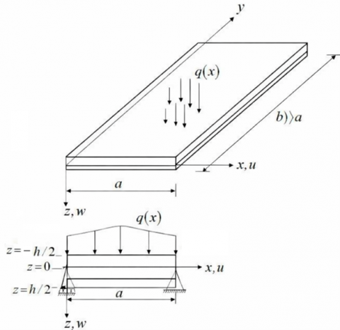
A laminated plate under cylindrical bending consists of orthotropic layers. The dimensions along the x and z axes are in the downward direction. Figure 1 illustrates the plate configuration under cylindrical bending. The upper surface of the plate $\left(z=-\frac{h}{2}\right)$ is exposed to thermal and mechanical loading.
(a) Plate in cylindrical bending condition
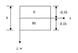
(b) Stacking sequence of the plate
Figure 1. Schematic representation of laminated composite plate subjected cylindrical bending (a) and (b)
2.2 Assumptions of quasi-3D theory
Refined plate theories are essential for analyzing laminated composites, particularly when transverse shear and normal effects become significant in thick laminates. The quasi-3D formulation extends classical approaches by incorporating thickness stretching and realistic shear distribution across the thickness. Based on these considerations, the assumptions are adopted.
The quasi-3D theory, as developed by Vo et al. [14], is an advanced structural modelling approach designed to overcome the limitations of traditional theory. The present quasi-3D formulation captures a realistic distribution of transverse shear strains and also permits thickness-direction stretching, such that $\left(\varepsilon_z \neq 0\right)$. This makes it effective for analyzing laminated composite structures, where the through-thickness effect plays a significant role. The theory introduces displacement fields that incorporate higher-order terms in the thickness coordinate, ensuring accurate representation of both bending and shear behaviour of the plate subjected to cylindrical bending conditions. From the above assumptions, the displacement field according to the quasi-3D formulation can be written as:
$u(x, z)=u_0-z \frac{\partial w_b(x)}{\partial x}-\frac{4}{3}\left(\frac{z^3}{h^2}\right) \frac{\partial w_s(x)}{\partial x}$ (1)
$w(x, z)=w_b(x)+w_s(x)+\left(1-4 \frac{z^2}{h^2}\right) w_z(x)$ (2)
In this formulation, $u(x, z)$ denotes the axial displacement along x axis, whereas $w(x, z)$ corresponds to the transverse displacement in the z-direction. Importantly, stretching in the thickness direction is permitted, reflecting the condition $\left(\varepsilon_z \neq 0\right)$.
3.1 Strain-displacement relationship
The strain-displacement relations in linear elasticity describe how the deformation of a body is related to the displacement of its points. According to this theory, the normal strain in the $x$ direction $\left(\varepsilon_x\right)$, the normal strain in the $z$ direction $\left(\varepsilon_z\right)$ and the shear strain $\left(\tau_{x z}\right)$ are obtained as follows.
$\varepsilon_x=\frac{\partial u(x, z)}{\partial x}$ (3)
$\varepsilon_z=\frac{\partial w(x, z)}{\partial z}$ (4)
$\tau_{x z}=\frac{\partial u(x, z)}{\partial z}+\frac{\partial w(x, z)}{\partial x}$ (5)
3.2 Constitutive relations
The constitutive relations define how stresses and strains are mathematically linked in a material under given loading and environmental conditions. The stress-strain relationship for a laminated composite plate in cylindrical bending is expressed by Eq. (6), which represents a reduced constitutive relation derived under the assumption of cylindrical bending of a laminated composite plate. In this case, only the stress components $\sigma_x, \sigma_z, \tau_{x z}$ and the corresponding strains are active, leading to a 3 × 3 constitutive matrix instead of the full 6 × 6 form. The reduced stiffness coefficients $\bar{Q}_{i j}$ are obtained from the transformed stiffness matrix of the laminate following classical laminate theory. Thermal expansion effects are included in the x and z directions. This reduction is consistent with the assumptions of plain strain in the x-z plane and neglect of stresses in the y direction as commonly adopted in laminated plate bending analysis [21].
$\left(\begin{array}{c}\sigma_x \\ \sigma_z \\ \tau_{x z}\end{array}\right)=\left[\begin{array}{ccc}\bar{Q}_{11} & \bar{Q}_{13} & 0 \\ \bar{Q}_{13} & \bar{Q}_{33} & 0 \\ 0 & 0 & \bar{Q}_{55}\end{array}\right]\left(\begin{array}{c}\varepsilon_x-\alpha_x \Delta T \\ \varepsilon_z-\alpha_z \Delta T \\ \gamma_{x_z}\end{array}\right)$ (6)
The left-hand side of Eq. (6) represents stress components. The right-hand side of the equation consists of strain components with thermal expansion terms in x and z directions multiplied by reduced elastic constants $\left(\bar{Q}_{i j}\right)$. The reduced elastic constants are as given below.
$\begin{gathered}\bar{Q}_{11}=\frac{E_1\left(1-\mu_{23} \mu_{32}\right)}{\Delta} \\ \bar{Q}_{13}=\frac{E_1\left(\mu_{31}+\mu_{21} \mu_{32}\right)}{\Delta} \\ \bar{Q}_{33}=\frac{E_3\left(1-\mu_{12} \mu_{21}\right)}{\Delta} \\ \bar{Q}_{55}=G_{13}\end{gathered}$ (7)
where,
$\Delta=\left[1-\mu_{12} \mu_{21}-\mu_{23} \mu_{32}-\mu_{31} \mu_{13}-2 \mu_{12} \mu_{23} \mu_{21}\right]$ (8)
The Young's moduli along $x$ (direction 1) and $z$ (direction 3) are represented by $E_1$ and $E_3$ respectively. They measure resistance to normal deformation. The shear modulus in the $x$-$z$ plane is denoted by $G_{13}$. This represents resistance to shear deformation. The Poisson ratios describing how strain in one direction induces strain in another perpendicular direction are denoted by $\mu_{12}, \mu_{21}, \mu_{13}, \mu_{23}, \mu_{31}, \mu_{32}$.
3.3 Temperature distribution
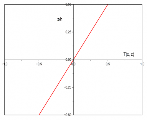
For a laminated composite plate undergoing cylindrical bending, the temperature difference through the thickness is assumed to vary linearly and is given by Eq. (9).
$\Delta T=\frac{2 z}{h} T_1(x)$ (9)
where, $\Delta T$ represents the temperature change measured from a chosen reference state. The temperature varies with both the in-plane coordinate x and the thickness coordinate z. The term $T_1(x)$ denotes the thermal loading, which varies along the length of the plate, while the temperature distribution remains linear through the thickness of the laminated composite plate in cylindrical bending conditions. In this work, the temperature field is directly prescribed and is not obtained by solving a heat conduction equation or problem. This assumption is used to simplify the analysis and to compare the present results with earlier or available studies on laminated composite plates under cylindrical bending. The selected or chosen form represents a linear temperature change across the thickness, which varies along the length of the plate through $T_1(x)$. However, this does not correspond to any specific physical thermal boundary condition, such as applied surface temperature or heat transfer. Hence, the results of this study are valid only for the assumed temperature distribution. A more realistic analysis would require solving the heat conduction equation to find the actual temperature variation, which can be considered in future work. The linear variation of temperature across the thickness is shown in Figure 2.
Figure 2. Linear variation of temperature across the thickness of a laminated composite plate subjected to cylindrical bending
The equations of motion are derived from the principle of virtual work by setting the virtual work of internal forces equal to that of the applied external loads. The assumed displacement field is substituted into the strain-displacement relations to obtain the strain components. By integrating the virtual work expression over the plate domain and enforcing its validity for arbitrary virtual displacements, the governing equations are obtained. When the principle is applied to a laminated composite plate undergoing cylindrical bending, it results in the governing relation presented in Eq. (10).
$\int_{-\frac{h}{2}}^{\frac{h}{2}} \int_0^a\left(\sigma_{x x} \delta \varepsilon_{x x}+\sigma_{z z} \delta \varepsilon_{z z}+\tau_{x z} \delta \gamma_{x z}\right) d x d z=0$ (10)
The variational operator in the above Eq. (10) is represented by $\delta$. By applying integration by parts and equating the coefficients of $\delta u_0, \delta w_b, \delta w_s, \delta w_z$ to zero, the resulting governing equations are obtained as Eqs. (11)-(14).
$\delta u_0:-A_{11} \frac{\partial^2 u_0}{\partial x^2}+B_{11} \frac{\partial^3 w_b}{\partial x^3}+\frac{4}{3 h^2} E_{11} \frac{\partial^3 w_s}{\partial x^3}+\frac{8}{h^2} B_{13} \frac{\partial w_z}{\partial x}=-\frac{2}{h} \frac{\partial T_1(x)}{\partial x}\left(T B_{11}+T B_{13}\right)$ (11)
$\delta w_b:-B_{11} \frac{\partial^3 u_0}{\partial x^3}+D_{11} \frac{\partial^4 w_b}{\partial x^4}+\frac{4}{3 h^2} F_{11} \frac{\partial^4 w_s}{\partial x^4}+\frac{8}{h^2} D_{13} \frac{\partial^2 w_z}{\partial x^2}=-\frac{2}{h} \frac{\partial^2 T_1(x)}{\partial x^2}\left(T D_{11}+T D_{13_z}\right)$ (12)
$\begin{aligned} & \delta w_s:-\frac{4}{3 h^2} E_{11} \frac{\partial^3 u_0}{\partial x^3}+\frac{4}{3 h^2} F_{11} \frac{\partial^4 w_b}{\partial x^4}+\frac{16}{9 h^4} H_{11} \frac{\partial^4 w_s}{\partial x^4}+\frac{\partial^2 w_s}{\partial x^2}\left(-A_{55}+\frac{8}{h^2} D_{55}-\frac{16}{h^4} F_{55}\right) + \frac{\partial^2 w_z}{\partial x^2}\left(\frac{32}{3 h^4} F_{13}-A_{55}+\frac{8}{h^2} D_{55}-\frac{16}{h^4} F_{55}\right)=-\frac{8}{3 h^2} \frac{\partial^2 T_1(x)}{\partial x^2}\left(T F_{11}+T F_{13}\right)\end{aligned}$ (13)
$\begin{gathered}\delta w_z:-\frac{8}{h^2} B_{13} \frac{\partial u_0}{\partial x}+\frac{8}{h^2} D_{13} \frac{\partial^2 w_b}{\partial x^2}+\frac{\partial^2 w_s}{\partial x^2}\left(\frac{32}{3 h^4} F_{13}-A_{55}+\frac{8}{h^2} D_{55}-\frac{16}{h^4} F_{55}\right)+\frac{\partial^2 w_z}{\partial x^2}\left(-A_{55}+\frac{8}{h^2} D_{55}-\frac{16}{h^4} F_{55}\right) +\frac{64}{h^4} D_{33} w_z=-\frac{16}{h^3} T_1(x)\left(T D_{13_x}+T D_{33}\right)\end{gathered}$ (14)
The stiffness coefficients $\left(A_{i j}, B_{i j} \ldots .\right.$. etc $)$ in the equations from Eqs. (11)-(14) are computed as given below.
$\begin{aligned} & \left(A_{i j}, B_{i j}, D_{i j}, E_{i j}, F_{i j}, H_{i j}\right) \\ & =\sum^N_{k=1} \int_{h_k}^{h_{k+1}} \bar{Q}_{i j}^{(k)}\left(1, z, z^2, z^3, z^4, z^6\right) d z\end{aligned}$ (15)
$\begin{aligned}\left(T B_{i j}, \mathrm{~T} D_{i j}, \mathrm{~T} F_{i j}\right) = \sum^N_{k=1}\left(\alpha_x\right) \int_{h_k}^{h_{k+1}} \bar{Q}_{i j}^{(k)}\left(z, z^2, z^4\right) d z\end{aligned}$ (16)
$\begin{aligned} & \left(T B_{i j}, \mathrm{~T} D_{i j}, \mathrm{~T} D_{i j}, T F_{i j}\right) \quad=\sum^N_{k=1}\left(\alpha_z\right) \int_{h_k}^{h_{k+1}} \bar{Q}_{i j}^{(k)}\left(z, z^2, z^4\right) d z\end{aligned}$ (17)
It is noted that the polynomial expansion in Eq. (15) includes the terms $\left(1, z, z^2, z^3, z^4, z^6\right)$. The absence of the $z^5$ term is not a typographical error but a direct outcome of the formulation. Due to the symmetry of the displacement field and the governing equations derived from the principle of virtual work, the term $z^5$ does not contribute to the expansion. The next significant term that naturally arises in the derivation is $z^6$, which is therefore retained in the polynomial set.
These relations collectively define the generalized stiffness coefficients through layer-wise integration of transformed reduced stiffness matrices.
Navier’s solution for simply supported laminated composite plates assumes trigonometric series expressions that satisfy boundary conditions along $(x=0)$ and $(x=a)$, the constraints are $w=0, M_x=0, N_x=0, M_x^s=0$, ensuring zero deflection, vanishing bending, in-plane force and shear moments. Here, $M_x^s$ denotes the moment resultant associated with the transverse shear deformation as defined in the adopted higher-order theory. Further, the problem is treated under a bending condition, where all field variables vary only along the x direction and remain constant along the y direction. This corresponds to an infinitely long plate with no variation in the transverse in-plane direction, thereby reducing the problem to a one-dimensional form.
$u_0(x)=\sum_{\infty}^{m=1} u_m \cos \left(\frac{m \pi x}{a}\right)$ (18)
$w_b(x)=\sum_{\infty}^{m=1} W_{b m} \sin \left(\frac{m \pi x}{a}\right)$ (19)
$w_s(x)=\sum_{\infty}^{m=1} W_{s m} \sin \left(\frac{m \pi x}{a}\right)$ (20)
$w_z(x)=\sum_{\infty}^{m=1} W_{z m} \sin \left(\frac{m \pi x}{a}\right)$ (21)
The thermal and mechanical loads are expanded in a single Fourier sine series as given below.
$T_1(x)=\sum_{\infty}^{m=1} T_{1 m} \sin \left(\frac{m \pi x}{a}\right)$ (22)
$q(x)=\sum_{m=1}^{\infty} q_m \sin \left(\frac{m \pi x}{a}\right)$ (23)
where, $q_m=q_0=1, T_{1 m}=T_0=1$ for sinusoidally distributed mechanical and thermal loads.
$q_m=\frac{4 q_0}{m \pi}$ and $T_{1 m}=\frac{4 T_0}{m \pi}$ for uniformly distributed mechanical and thermal loads. By substituting Eqs. (18)-(23) into the governing Eqs. (11)-(14), the system reduces to a set of coupled algebraic expressions. These can be compactly represented in matrix form, facilitating solution through standard linear algebra techniques and represented by the following Eq. (24).
$[K]\{X\}=\{f\}$ (24)
The stiffness matrix, unknowns and force vector are represented by $[K],\{X\}$ and $\{f\}$ respectively in the above Eq. (24). The stiffness matrix obtained and its elements are written as below.
$[K]=\left[\begin{array}{llll}k_{11} & k_{12} & k_{13} & k_{14} \\ k_{21} & k_{22} & k_{23} & k_{24} \\ k_{31} & k_{32} & k_{33} & k_{34} \\ k_{41} & k_{42} & k_{43} & k_{44}\end{array}\right]$ (25)
The elements of $[K]$ matrix are written below.
$\begin{gathered}k_{11}=A_{11} \alpha^2, k_{12}=-B_{11} \alpha^3, \\ k_{13}=-\frac{4}{3 h^2} B_{11} \alpha^3, k_{14}=\frac{8}{h^2} B_{13} \alpha, \\ k_{21}=k_{12}, k_{22}=D_{11} \alpha^4, k_{23}=\frac{4}{3 h^2} F_{11} \alpha^4, \\ k_{24}=-\frac{8}{h^2} D_{13} \alpha^2 \\ k_{31}=k_{13}, k_{32}=k_{23}, \\ k_{33}=\frac{16}{9 h^4} H_{11} \alpha^4+\left(A_{55}-\frac{8}{h^2} D_{55}+\frac{16}{h^4} F_{55}\right) \alpha^2 \\ k_{34}=\left(-\frac{32}{9 h^4} F_{13}+A_{55}-\frac{8}{h^2} D_{55}+\frac{16}{h^4} F_{55}\right) \alpha^2 \\ k_{41}=k_{14}, k_{42}=k_{24}, k_{43}=k_{34}, \\ k_{44}=\frac{64}{h^4} D_{33}+\left(A_{55}-\frac{8}{h^2} D_{55}+\frac{16}{h^4} F_{55}\right) \alpha^2 \end{gathered}$ (26)
The unknowns to be determined and force matrix elements are as below.
$\{X\}=\left\{\begin{array}{c}u_m \\ w_{b m} \\ w_{s m} \\ w_{z m}\end{array}\right\}$ (27)
$\{f\}=\left\{\begin{array}{c}f_1=-\frac{2}{h} \alpha\left(T B_{11}+T B_{13}\right) T_{1 m} \\ f_2=\frac{2}{h} \alpha^2\left(T D_{11}+T D_{13}\_z\right) T_{1 m} \\ f_3=\frac{8}{3 h^3} \alpha^2\left(T F_{11}+T F_{13}\right) T_{1 m} \\ f_4=-\frac{16}{h^3}\left(T D_{13 \_x}+T D_{33}\right) T_{1 m}\end{array}\right\}$ (28)
In the above Eq. (26), $\alpha=\frac{m \pi}{a}$. The unkowns $\{X\}$ can be evaluated by solving above set of algebric equations. Further, displacements and stresses can be obtained under thermal and mechanical loads.
The transverse shear stress in elasticity can be obtained by applying the shear stress-free boundary conditions at the top and bottom surfaces and integrating the equilibrium equation for $\tau_{z x}$ with respect the thickness coordinate. This leads to the following expression.
$\tau_{x z}^{E E}=\int_{-h / 2}^{Z_{k+1}} \frac{\partial \sigma_{x x}}{\partial x} d z+C_1$ (29)
where, $\sigma_{xx}$ is normal stress in the $x$ direction, $h$ is the total thickness, $z_{k+1}$ represents the upper limit of integration along the thickness coordinate and $C_1$ is the constant of integration determined from the boundary conditions.
5.1 Numerical implementation
The governing equations are solved using Navier’s method by expressing the displacement variables in the form of a trigonometric series that satisfy the simply supported conditions. For the considered loading condition, the solution is dominated by the fundamental term $(m=1)$, which satisfied the simply supported boundary conditions and represented the primary deformation mode. It was observed that the inclusion of higher order terms does not produce any significant change in the results. Therefore, only the first is retained in the present computation.
The constant of integration $\left(C_1\right)$ in Eq. (29) is determined by enforcing the transverse shear stress-free boundary condition at the plate surfaces, i.e., $\tau_{x z}=0$ at $z= \pm \frac{h}{2}$. This condition is applied after performing the thickness-wise integration of the equilibrium equation, ensuring that the computed shear stress distribution satisfies the physical boundary requirements.
For laminated plates, the integration through the thickness is carried out layer-wise. The stress components are first evaluated within each layer using the corresponding material properties and continuity of stresses is maintained at the layer interfaces. The total response is then obtained by assembling the contributions from all layers.
The complete formulation and solution procedure are implemented in MATLAB software. Standard numerical routines are used to evaluate derivatives and perform integrations involved in the formulation.
A two-layer asymmetric laminated composite plate undergoing cylindrical bending is examined under both mechanical and thermal loading conditions. The plate response is investigated through a detailed numerical study using graphite-epoxy as the constituent material. The orthotropic material properties employed in the analysis are as follows:
The longitudinal and transverse elastic moduli are:
$E_1=172.4\,\, \mathrm{GPa}, E_2=E_3=6.89\,\, \mathrm{GPa}$
The shear moduli are:
$G_{12}=3.448\,\, \mathrm{GPa}, G_{23}=1.375\,\, \mathrm{GPa}, G_{31}=3.448\,\, \mathrm{GPa}$
The Poisson ratios are taken as:
$\mu_{12}=0.25, \mu_{23}=0.25, \mu_{31}=0.25$
The ratio of transverse to longitudinal coefficients of thermal expansion is assumed to be $\frac{\alpha_T}{\alpha_L}=1125$.
These properties are adopted to comprehensively examine the thermal and mechanical behaviour of the plate subjected to cylindrical bending. In addition to material properties, the geometric and loading parameters used in the present analysis are specified to ensure reproducibility. The plate has a length a and total thickness h with the aspect ratio (a/h) equal to 4 and 10. The laminate consists of two layers arranged in an asymmetric stacking sequence (0°/90°), where 0° means fibers are parallel to the x-axis and 90° indicates fibers are perpendicular to the x-axis. The top layer is zero degrees (0°) and the bottom layer is 90°. Each layer has equal thickness. The plate is simply supported along its edges $x=0$ and $x= a$ satisfying conditions $w=0, M_x=0, N_x=0, M_x^s=0$. Cylindrical bending is assumed, all field variables vary only in the $x$ direction and remain constant along the $y$ direction. The mechanical loading is applied as a sinusoidal transverse load represented by $q(x)=\sum_{m=1}^{\infty} q_m \sin \left(\frac{m \pi x}{a}\right)$. The thermal loading is defined through the prescribed temperature field $\Delta T=\frac{2 z}{h} T_1(x)$, where $T_1(x)=\sum_{\infty}^{m=1} T_{1 m} \sin \left(\frac{m \pi x}{a}\right)$. All results presented are based on the above-defined geometry, material properties and loading conditions.
6.1 Numerical results
This section presents a detailed numerical investigation of the deformation and stress characteristics of the two-layer asymmetric (0°/90°) laminated composite plate subjected to cylindrical bending. The analysis considers both mechanical and thermal loading cases to assess the predictive capability and accuracy of the proposed formulation. The results are reported in terms of non-dimensional displacements and stresses to facilitate meaningful comparison with existing higher-order theories and reference solutions available in the literature. The computed axial displacement $(\bar{u})$, transverse displacement ($\bar{w}$), normal stress ($\bar{\sigma}_{x x}$) and transverse shear stress computed by using the equilibrium equation $\left(\tau_{x z}^{E E}\right)$ for different aspect ratios $(s=a / h)$, while the corresponding variations are further illustrated through graphical representation in Figures 3-8.
To present the results in general form, the displacement and stress quantities are expressed in non-dimensional form for both mechanical and thermal loading cases. The normalization is carried out using characteristic geometric, material and loading parameters. The symbols used in non-dimensional expressions are defined in Table 1.
Table 1. Non-dimensional quantities used in the analysis
|
Quantity |
Non-Dimensional Form |
Definition/Description |
|
Mechanical loading |
||
|
$\bar{u}$ |
$\frac{b E_3 u}{q_0 h}$ |
In-plane displacement at x=0 and z = -h/2 |
|
$\bar{w}$ |
$\frac{100 E_3 w h^3}{q_0 a^4}$ |
Transverse displacement at x = a/2 = 0 |
|
$\bar{\sigma}_{x}$ |
$\frac{b \sigma_x}{q_0}$ |
Normal stress at x = a/2 and z= -h/2 |
|
$\bar{\tau}_{z x}^{E E}$ |
$\frac{b \tau_{x z}}{q_0}$ |
Shear stress at x = 0 and z = -0.24 h |
|
Thermal loading |
||
|
$\bar{u}$ |
$\frac{u}{\alpha_{L} T_1 a}$ |
In-plane or axial displacement under thermal load at x = 0 and z = -h/2 |
|
$\bar{w}$ |
$\frac{h w}{\alpha_L T_1 a^2}$ |
Transverse displacement under thermal load at x = a/2 = 0 |
|
$\bar{\sigma}_{x}$ |
$\frac{\sigma_x}{\alpha_L T_1 E_T}$ |
Normal stress under thermal load x = a/2 and z = -h/2 |
|
$\bar{\tau}_{z x}^{E E}$ |
$\frac{\tau_{x z}}{\alpha_L T_1 E_T}$ |
Shear stress under thermal load at x = 0 and z = -0.24 h |
|
b |
- |
Plate width (taken as unity in cylindrical bending) |
|
$E_T$ |
- |
Reference Modulus (taken as E2) |
|
$q_0$ |
- |
Load intensity amplitude |
|
$T_1$ |
- |
Thermal load amplitude |
In the mechanical loading case, b denotes the plate width, which is taken as unity under cylindrical bending and $q_0$ represents the amplitude of the applied transverse load. The factor 100 used in the transverse displacement expression is introduced only for scaling purposes to bring the magnitude of deformation to a convenient numerical range as commonly adopted in the literature.
In the thermal loading case, $E_T$ represents a reference elastic modulus used for normalization (considered as $E_2$), and $\alpha_L T_1$ defines the characteristic thermal strain based on the longitudinal coefficient of thermal expansion ($\alpha_L$) and thermal load amplitude $\left(T_1\right)$.
The non-dimensional quantities used in the analysis are presented in the following Table 1.
7.1 Response of the laminate under mechanical loading
The results of stresses and displacements under sinusoidal and uniform mechanical load obtained using quasi-3D and PSDT are shown in Table 2.
Table 2. Non-dimensional displacements and stress components of a two-layer (0°/90°) asymmetric laminated plate subjected to cylindrical bending under mechanical loading
|
Sinusoidally Distributed Mechanical Load |
|||||
|
Model |
S |
$\bar{u}$ |
$\bar{w}$ |
$\bar{\sigma}_{xx}$ |
$\bar{\tau}_{z x}^{E E}$ |
|
Quasi-3D |
4 |
1.70 |
4.46 |
33.41 |
2.97 |
|
PSDT |
1.68 |
4.39 |
33.23 |
2.94 |
|
|
Sayyad and Ghugal [3] |
1.71 |
4.39 |
33.85 |
2.99 |
|
|
Pagano [13] |
1.55 |
4.32 |
30.02 |
2.70 |
|
|
Quas-3D |
10 |
22.80 |
2.90 |
179.09 |
7.35 |
|
PSDT |
22.73 |
2.89 |
178.77 |
7.34 |
|
|
Sayyad and Ghugal [3] |
22.89 |
2.90 |
180.66 |
7.38 |
|
|
Pagano [13] |
23.42 |
2.95 |
175.00 |
7.30 |
|
|
Uniformly Distributed Mechanical Load |
|||||
|
Model |
S |
$\bar{u}$ |
$\bar{w}$ |
$\bar{\sigma}_{xx}$ |
$\bar{\tau}_{z x}^{E E}$ |
|
Quas-3D |
4 |
2.17 |
5.67 |
42.54 |
3.78 |
|
PSDT |
2.14 |
5.59 |
42.31 |
3.74 |
|
|
Sayyad and Ghugal [3] |
2.26 |
5.51 |
40.52 |
5.08 |
|
|
Quas-3D |
10 |
29.03 |
3.69 |
228.03 |
9.36 |
|
PSDT |
28.94 |
3.68 |
227.62 |
9.34 |
|
|
Sayyad and Ghugal [3] |
29.74 |
3.67 |
221.54 |
11.59 |
|
Note: PSDT = parabolic shear deformation theory
The results evaluated by quasi-3D and PSDT are very close to each other for both thick and thin laminates in cylindrical bending.
These results are also close to the exact elasticity solution and the results evaluated by SSNPT available in the literature. At low aspect ratio (a/h = 4), these models predict displacement and stresses that nearly match the exact elasticity solution, confirming their reliability. When the aspect ratio (a/h) changes to 10, the refined theories continue to align well with the exact elasticity solution.
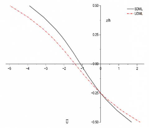
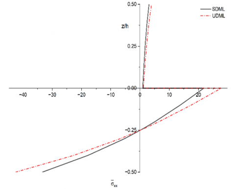
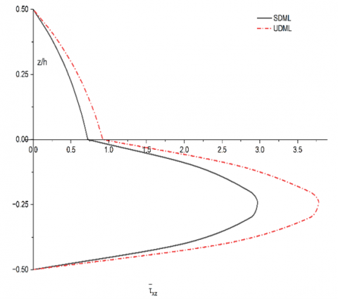
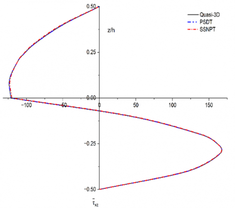
The variation of the normalized in-plane or axial displacement $\bar{u}$, normal stress $\bar{\sigma}_{xx}$ and transverse shear stress $\bar{\tau}_{x z}$ across the thickness of the plate under sinusoidal and uniform mechanical load is shown in Figures 3-5, respectively. The variation of axial displacement through the thickness shows distinct differences between sinusoidal and uniform loadings. Under sinusoidal load, the displacement distribution is smoother and more gradual, reflecting the periodic nature of the applied force. Whereas a uniform load produces a more consistent displacement profile with noticeable change near the mid-plane (Figure 3).
Figure 3. Axial displacement ($\bar{u}$) under sinusoidal and uniform mechanical load for an aspect ratio of 4
This highlights how the type of mechanical load strongly influences the deformation pattern of the laminate in cylindrical bending. The normal stresses (Figure 4) vary significantly across the thickness. Figure 4 indicates that sinusoidal loading introduces localized stress variation, while uniform loading distributes stresses more evenly across the laminates.
Figure 4. Normal stress ($\bar{\sigma}_{xx}$) under sinusoidal and uniform mechanical load for an aspect ratio of 4
Figure 5. Transverse shear stress ($\bar{\tau}_{x z}$) under sinusoidal and uniform mechanical load for an aspect ratio of 4
The transverse shear stress shows strong dependence on the type of loading (Figure 5). In the case of sinusoidal loading, the shear stress curve is more oscillatory, whereas uniform loading produces a smoother distribution with maximum shear stress occurring at the mid-plane. This demonstrates that sinusoidal loads amplify shear variations across the thickness of the plate in cylindrical bending, whereas uniform loads give a more predictable shear response.
In addition, the quasi-3D formulation includes transverse normal strain ($\varepsilon_z$), which introduces thickness stretching and coupling with transverse normal stress ($\sigma_z$). Although this effect is small under mechanical loading in cylindrical bending, it slightly improves the accuracy of stress prediction compared to PSDT, which neglects this contribution.
7.2 Response of the laminate under thermal loading
For the thermal loading case, results from the exact elasticity solution reported by Pagano [13] are not included in Table 3, as thermal benchmark data for the (0°/90°) configuration are not available in that reference. Therefore, validation of the present results is carried out through comparison with other refined plate theories, such as PSDT and SSNPT, which are well established in the literature. The results are obtained by using quasi-3D, PSDT and SSNPT theories and compared with each other for validation purposes.
Table 3. Non-dimensional displacements and stress components of a two-layer (0°/90°) asymmetric laminated plate subjected to cylindrical bending under thermal loading
|
Sinusoidally Distributed Thermal Load |
|||||
|
Model |
S |
$\bar{u}$ |
$\overline{\boldsymbol{W}}$ |
$\bar{\sigma}_{x}$ |
${\tau}_{z x}^{E E}$ |
|
Quas-3D |
4 |
28.13 |
32.43 |
2040.42 |
158.50 |
|
PSDT |
28.13 |
32.43 |
2040.42 |
158.50 |
|
|
SSNPT |
28.24 |
31.93 |
2007.54 |
158.75 |
|
|
Quas-3D |
10 |
27.06 |
36.82 |
1957.39 |
63.18 |
|
PSDT |
27.06 |
36.82 |
1957.39 |
63.18 |
|
|
SSNPT |
27.17 |
36.86 |
1924.49 |
63.23 |
|
|
Uniformly Distributed Thermal Load |
|||||
|
Model |
S |
$\bar{u}$ |
$\overline{\boldsymbol{W}}$ |
$\bar{\sigma}_{xx}$ |
${\tau}_{z x}^{E E}$ |
|
Quas-3D |
4 |
35.81 |
41.29 |
2597.94 |
201.80 |
|
PSDT |
35.81 |
41.29 |
2597.94 |
218.43 |
|
|
SSNPT |
35.95 |
40.65 |
2556.08 |
218.76 |
|
|
Quas-3D |
10 |
34.46 |
46.88 |
2492.23 |
80.44 |
|
PSDT |
34.46 |
46.88 |
2492.23 |
87.09 |
|
|
SSNPT |
34.60 |
46.93 |
2450.33 |
87.16 |
|
The results of thermal stresses and displacement under sinusoidal thermal load evaluated using quasi-3D, parabolic (PSDT) and sinusoidal shear and normal plate theory (SSNPT) are shown in Table 3. In the case of a lower aspect ratio (a/h = 4), the quasi-3D and PSDT models give identical predictions for displacement and stresses, showing that both theories capture the thermal response very well.
A slight difference is noted in the values evaluated by the SSNPT model. The results of all three refined theories remain close to each other, confirming their accuracy in representing thermal effects in laminated plates in cylindrical bending. The transverse shear stresses drop significantly when the aspect ratio changes to 10. This indicates the reduced influence of shear effect as the plate becomes thinner.
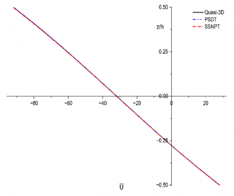
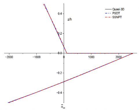
The variation of the normalized in-plane or axial displacement $\bar{u}$, normal stress $\bar{\sigma}_{xx}$ and transverse shear stress $\bar{\tau}_{x z}$ through the thickness of the plate in cylindrical bending under sinusoidal thermal load is shown in Figures 6-8, respectively. The axial displacement (Figure 6) occurs near the outer surfaces, while the mid-plane experiences a smaller value. The normal stress changes significantly through the thickness (Figure 7).
Figure 6. Axial displacement ($\bar{u}$) under sinusoidal thermal load for an aspect ratio of 4
Figure 7. Normal stresses ($\bar{\sigma}_{xx}$) under sinusoidal thermal load for an aspect ratio of 4
Figure 8. Transverse shear stress ($\bar{\tau}_{x z}$) under sinusoidal thermal load for an aspect ratio of 4
Under sinusoidal thermal load, the normal stress distribution is asymmetric with higher values near the outer layers. This reflects the strong effect of thermal gradients on the laminates under cylindrical bending conditions. The transverse shear stress profile shows peaks closer to the mid-plane and decreasing towards the surfaces.
The identical results obtained using the quasi-3D and PSDT theories are due to the present cylindrical bending condition and the assumed thermal loading; both theories reduce to a similar form in terms of displacement field representation. In particular, the contribution of thickness stretching and higher order terms in the quasi-3D model becomes negligible for the selected laminate configuration and loading case. As a result, both models predict nearly the same response for in-plane displacement, transverse displacement and normal stress. However, a difference between the two theories is observed in the transverse shear values, especially under uniform thermal loading. This is because the quasi-3D theory accounts for transverse normal deformation. Further, it is observed that transverse shear stress is more sensitive to the type of thermal loading and plate thickness. For thicker plate (lower a/h), shear stresses are high due to stronger through-thickness interaction. As the plate becomes thinner (a/h = 10), the shear stress reduces significantly, indicating that bending behaviour dominates and shear effects become less.
The close agreement between quasi-3D and PSDT results is limited to the present loading and boundary conditions and may not hold for cases involving strong thickness stretching effects or different thermal boundary conditions.
Under thermal loading, the effect of transverse normal strain ($\varepsilon_z$) becomes more relevant due to temperature variation across the thickness. The quasi-3D model captures this through thickness stretching while PSDT neglects it. However, for present loading, this contribution remains small for displacement and normal stress, leading to identical results. Its influence is more noticeable in transverse shear stress due to coupling between thermal gradients and through-thickness deformation.
The study of laminated plates under mechanical and thermal loads shows that refined theories such as quasi-3D, PSDT and SSNPT give results that are very close to the elasticity solution. This indicates that these theories are reliable for predicting stresses and displacements. These models capture the effect of transverse shear and normal stresses, which are important for thick plates in cylindrical bending. In contrast, the traditional plate theory often underestimates both stresses and displacements, especially when the aspect ratio is small, i.e., thick laminate, showing that it is suitable for thin laminates in cylindrical bending. The sinusoidal shear and normal plate theory sometimes predict slightly higher stress values, but it still performs better than traditional plate theory and remains consistent with the exact elasticity solution. The limitation of this work is the use of Navier’s solution, which is applicable to simply supported boundary conditions. The other possible boundary conditions, such as clamped edges, free edges and mixed boundary conditions (e.g., one clamped and the other simply supported) are not explored in the present study. Another limitation of this work is that it focuses only on two-layer laminates and specific loading conditions, which may not cover all practical applications. Further research can extend these models to multilayered composites in cylindrical bending, nonlinear thermal effects and dynamic loading, making them more useful for advanced engineering fields such as aerospace and automotive.
It is important to note that the present work does not propose a new theory. Instead, it demonstrates the effectiveness of existing quasi-3D and PSDT models in predicting thermal/mechanical behaviour of asymmetric laminate in cylindrical bending. The results presented may be used as benchmark solutions for similar configurations and loading conditions.
|
S |
Aspect Ratio (a/h) |
|
h |
Total Thickness of Plate |
|
a |
Length along x-axis |
|
E |
Modulus of Elasticity |
|
SDML |
Sinusoidal Distributed Mechanical Load |
|
UDML |
Uniformly Distributed Mechanical Load |
|
Greek symbols |
|
|
$\mu$ |
Poisson's Ratio |
|
$\alpha$ |
Coefficient of Thermal Expansion |
|
$\tau_{z x}^{E E}$ |
Transverse shear stress obtained from the equilibrium equation |
[1] Alibakhshi, R. (2012). The effect of anisotropy on free vibration of rectangular composite plates with patch mass. International Journal of Engineering, 25(3): 223-232. https://www.ije.ir/article_72018.html.
[2] Thilak, J.A.J., Suresh, P. (2022). Dynamic response of glass/epoxy laminated composite plates under low-velocity impact. International Journal of Engineering, 35(7): 1283-1290. http://doi.org/10.5829/ije.2022.35.07a.07
[3] Sayyad, A.S., Ghugal, Y.M. (2016). Cylindrical bending of multilayered composite laminates and sandwiches. Advances in Aircraft and Spacecraft Science, 3(2): 113-148. http://doi.org/10.12989/aas.2016.3.2.113
[4] Atallah, K.E., Ouinas, D., Zaoui, F.Z., Khoussa, H., Achour, B., Hassan, M.F., Siregar, J.P. (2025). A refined quasi-3D higher-order shear deformation theory for static, free vibration, and buckling of laminated composite plates on kerr-type foundation. Next Materials, 9: 101352. https://doi.org/10.1016/j.nxmate.2025.101352
[5] Bakhtiari-Nejad, F., Aryana, F., Naseralavi, M., Mirzaeifar, R. (2008). Analysis of natural frequencies for a laminated composite plate with piezoelectric patches using the first and second eigenvalue derivatives. International Journal of Engineering, 21(1): 85-96.
[6] Belkhodja, Y., Ouinas, D., Fekirini, H., Olay, J.V., Touahmia, M. (2020). Three new hybrid quasi-3D and 2D higher-order shear deformation theories for free vibration analysis of functionally graded material monolayer and sandwich plates with stretching effect. Advanced Composites Letters, 29. https://doi.org/10.1177/0963693520941865
[7] Doan, T.N., Hung, T.V., Quang, D.V. (2022). Thermal bending analysis of FGM cylindrical shells using a quasi-3D type higher-order shear deformation theory. In Modern Mechanics and Applications, pp. 316-330. https://doi.org/10.1007/978-981-16-3239-6_24
[8] Houari, T., Bessaim, A., Houari, M.S.A., Benguediab, M., Tounsi, A. (2018). Bending analysis of advanced composite plates using a new quasi 3D plate theory. Steel and Composite Structures, 26(5): 557-572. https://doi.org/10.12989/scs.2018.26.5.557
[9] Khiloun, M., Bousahla, A.A., Kaci, A., Bessaim, A., Tounsi, A., Mahmoud, S.R. (2020). Analytical modeling of bending and vibration of thick advanced composite plates using a four-variable quasi 3D HSDT. Engineering with Computers, 36: 807-821. https://doi.org/10.1007/s00366-019-00732-1
[10] Kulkarni, S.K. (2025). Nonlinear effects on cylindrical bending of orthotropic plate: A computational study. Revue des Composites et des Materiaux Avances, 35(5): 893-900. https://doi.org/10.18280/rcma.350509
[11] Maji, A., Mahato, P.K. (2022). Development and applications of shear deformation theories for laminated composite plates: An overview. Journal of Thermoplastic Composite Materials, 35(12): 2576-2619. https://doi.org/10.1177/0892705720930765
[12] Naik, N.S., Sayyad, A.S. (2021). Higher-order displacement model for cylindrical bending of laminated and sandwich plates subjected to environmental loads. Mechanics of Advanced Composite Structures, 8(1): 185-201. https://doi.org/10.22075/macs.2020.20242.1253
[13] Pagano, N.J. (1969). Exact solution for composite laminates in cylindrical bending. Journal of Composite Materials, 3(3): 398-411. https://doi.org/10.1177/002199836900300304
[14] Vo, T.P., Thai, H.T., Nguyen, T.K., Inam, F., Lee, J. (2015). Static behaviour of functionally graded sandwich beams using a quasi-3D theory. Composites Part B: Engineering, 68: 59-74. http://doi.org/10.1016/j.compositesb.2014.08.030
[15] Mathapati, S.R., Ghugal, Y.M., Sayyad, A.S. (2025). Nonlinear thermo-mechanical bending analysis of laminated composite plates using trigonometric shear deformation theory. Mechanics of Advanced Materials and Structures, 2025: 2588806. http://doi.org/10.1080/15376494.2025.2588806
[16] Rajeh, M.A., Al-Dulaijan, S.U., Bourada, F., Al-Osta, M.A., Tounsi, A., Yaylaci, M., Tounsi, A. (2025). On the thermal bending behavior of porous cross-ply laminated plates using an improved first-order shear deformation theory. Acta Mechanica, 236: 4177-4195. https://doi.org/10.1007/s00707-025-04369-8
[17] Gajbhiye, P.D., Bhayya, V., Ghugal, Y.M. (2025). Bending analysis of sandwich plates under concentrated force using quasi-three-dimensional theory. AIAA Journal, 60(1): 316-329. https://doi.org/10.2514/1.J060815
[18] Si, J., Yi, S. (2024). A quasi 3D model of composite laminated micro plates based on modified couple stress theory under thermal loading. Mechanics of Advanced Materials and Structures, 31(14): 2943-2954. https://doi.org/10.1080/15376494.2023.2166172
[19] Kulkarni, S. (2025). A higher order computational model for thermal analysis of orthotropic plate in cylindrical bending. Civil and Environmental Engineering, 21(1): 1-9. https://doi.org/10.2478/cee-2025-0001
[20] Reddy, J.N. (2003). Mechanics of Laminated Composite Plates and Shells: Theory and Analysis (2nd edition). Boca Raton: CRC Press. https://doi.org/10.1201/b12409
[21] Sayyad, A.S., Ghugal, Y.M., Kant, T. (2024). Quasi-3D flexural analysis of laminated composite plates resting on elastic foundations using higher-order displacement model. Progress in Engineering Science, 1(2-3): 100005. https://doi.org/10.1016/j.pes.2024.100005
[22] Gwak, Y., Nguyen, S.N., Kim, J.S., Park, H., Lee, J., Han, J.W. (2024). Improved finite element thermomechanical analysis of laminated composite and sandwich plates using the new enhanced first-order shear deformation theory. Mathematics, 12(7): 963. https://doi.org/10.3390/math12070963
[23] Li, J.J., Qian, H., Lu, C.H. (2025). Thermo-mechanical analysis for composite cylindrical shells with temperature-dependant material properties under combined thermal and mechanical loading. Materials, 18(7): 1391. https://doi.org/10.3390/ma18071391