Mustafa M. Mansour*![]() | Azhar Mansoor Salman
| Azhar Mansoor Salman![]() | Alaa M. Lafta
| Alaa M. Lafta![]()
© 2025 The authors. This article is published by IIETA and is licensed under the CC BY 4.0 license (http://creativecommons.org/licenses/by/4.0/).
OPEN ACCESS
This paper is concerned with the analysis of the design of a wheel rim that will exhibit higher resistance to failure, stiffness, strength and ductility. Production of wheel rims, traditionally, has been designed on low-performance materials, but in this study, we instead consider high-performance materials like titanium and tungsten to assess their potential applicability in production. It was studied through a finite element analysis (FEA) simulation, and then verified through real-time tests conducted on prepared pieces in a simulated loading environment. Findings show that titanium and tungsten rims have a higher bending and impact strength than the standard material. In the experiment, aluminum, steel, and high-performance rim materials exhibit deflection under 8.195 mm, 3.698 mm, and 1.921 mm, and a corresponding bending stress value of 4.981 MPa, 6.112 MPa, and 9.718 MPa, respectively. The study also introduces a new innovative design of introducing a high-performance elastomeric rubber between the body of the rim and the hub to help absorb operating stresses to improve durability. Other aspects of the research are considering the enhancement of natural frequency to achieve improved dynamic performance. The results indicate the originality of this design could generate a great improvement in the reliability and performance of rim wheels thus appropriate in large vehicles and facilities which have portfolios in large cities and may be also applicable in businesses.
material structure, steel alloy, FEA, wheel rims design
In recent times, the automobile industry is pushing the engineering boundaries by introducing new challenges both in terms of designing, as well as the adaptive material behavior of high-performance materials under loading conditions. The advent of stringent emission norms has led to the inception of turbocharged gasoline directs injection engines and continuous variable transmission (CVT) vehicles, which can sustain high thermal loads and harsh working conditions. This new trend and requirement in vehicles have led to the inception and mass production of high-performance steel and aluminum, which can lead to intricate properties when exposed to mechanical loading. Therefore, to further explore the technological advancements in modern-day automobiles, this paper is primarily focused on the design and optimization of a wheel rim using finite element analysis [1].
Lighter wheels also improve the response of the suspension system due to the decreased unsprung and rotating components of the vehicle. Commercial research indicates one major concept that has widely employed computer-aided project methods in the form of topology structure to ensure high performance rim. It was followed by the optimization project method used to derive a topology structure.
From additional viewpoints on shape formation, the final rim structures are described in detail. The first computer-aided project method of the rim model is initiated through the internal structural efficiency assessment, taking into account the stress-strain curves and the rolling techniques of aluminum alloy materials. Another concept involves the redesign dimensions influenced by the stress concentration to find out the weight of the product. This concept also reduces rim stresses by employing an equalization technique and the depth of the concave wheel. The concave wheel carcass minimizes weight, while a technology called roller frictionization minimizes the roll width. New materials for wheel rim components, such as aluminum alloy, ensure the weight of the product; the effectiveness is marked at 50% to 60%. This study further investigates a lightweight design wheel rim. An innovative concept employing well-proven and simply constructed design features is then developed taking into account the following considerations for the robotic rotary drums: suitable forming time, the possibility to reprocess the forming, employment of additional tools, the use of different forming parameters depending on the robotic features, and suitable tests for the assessment of the formed component profiles. The fabricated wheel rim, based on FEA simulation, must comply with the standard tire bead of 35 kg and the regulations for fatigue and impact strengths. The hoop tension in the product must also be verified by the experimental tests [2]. The design of wheels is changing rapidly with the time for the competition of making it light and cost-effective. This paper presents the selection of materials and critical study of AMMC (Aluminum Metal Matrix Composite) wheels manufactured through casting. Later on, a design has been presented for lightweight wheels by changing the AMMC to a fiber-reinforced plastic composite. Different samples of materials have been studied under the action of radial forces at different speed and results like the stress, strain, maximum deformation, temperature, and von-Mises stress have been compared. The design of a new composite wheel has been compared with the initial AMMC. The manufacturing of the wheel is a cost-effective and lightweight. The use of FEA in the automotive industry to assist in the design process is well established, but until recently this has been limited to 2D analysis 2. 3-D elements require a far larger number of nodes than plane stress or shell elements and as a result, are often more difficult to use without powerful computers. For buckling analysis, the availability of third principal stress would allow a more precise prediction of buckling strength. A similar option would be potentially beneficial for FEM users and therefore, this work focuses on generating all three mid-thickness stress components for a general 8-node shell elements.
1.1 Background and significance
Automobile designs and performance drivability are increasingly being explored from the available components to the most complex components like frame, engine parts, wheel rims, and tooling, etc. Wheels are those parts in an automobile that play a significant role in an automobile’s overall safety. They have also a stake in the vehicle’s overall performance. To design wheels for improvements in vehicle safety and performance, many researchers are devoted not only to the traditional design methodologies involving structural analysis, but also to the analysis using advanced simulation tools. This study is dedicated to performing a FEA of a wheel rim designed using aluminium alloys as shown in Table 1. To start the FEA, first, the drawing of the wheel geometry is received from the designing department. The FEA begins by building the wheel geometrical model by using the drawing geometry. The FEA is performed. Finally, the fatigue factors of safety are calculated at dangerous areas. The result of the fatigue analysis is taken as a result on which the critical areas have to be changed and a new design of the wheel is proposed. The use of Fourier transforms and their corresponding fast stress calculations is demonstrated within the example of the design evaluation of a cast wheel rim. The truncated series solution offers significant advantages in terms of both accuracy and reduced computational effort as compared to the application of the inverse transform. However, the form of the limit solution restricts the ability to address complex analytical systems. An extensive but consistent and clear design and manufacture would enable real application of these results. Wheel rims are the most important and special components of wheels because they act as a support for tires and tune vehicle performance for different platforms. Rims are made from various materials and different joining techniques are used to manufacture rims based on their application and physical requirements [3]. Most of the rims are machined aluminum sheets and made with fabrication or forging processes to transform them into the required shape for the wheels, and a few are made with carbon composites. Lightweight and high-strength composite materials are mostly preferred for the wheel rim application due to their good mechanical and thermal properties [4].
A continuous increase in energy costs and pollution levels due to the excessive use of traditional vehicular systems is a problem in transportation. One way to mitigate this situation is to produce high-efficiency or low-pollutant mechanism systems in the transportation sector [5]. The relationship between the properties of wheel rims and their design is an important issue of interest because it directly affects ride quality and fuel consumption. At this point, this is because the wheel rim is the transition element between the tire and the vehicle, and it affects the vehicle in terms of various parameters such as vibration, force, and comfort. During driving, the inertia of the wheel rim has a huge effect on the parts touching the wheel rim. At the same time, the wheel rim is the field where the most studies are carried out with respect to other vehicle parts. The wheel rim, although it is not visible from the point of view of the head, has a greater effect on the performance of the vehicle in the 1000 hertz range vibrations. Compared to traditional wagon tires, made using special materials to achieve ultra-low tire weight, such as carbon fiber and aluminum prefilamentirana, results in less spring deflection and energy slits, and enables high-speed circulation. In particular, finite element (FE) used to analyze wheel rims are extremely important [6, 7].
In this study, the design and FEA of the simplified rear wheel rim model were carried out. Initially, traditional materials used for the wheel rim are presented historically, accompanied by some basic data about wheel rims in general. The methodology of reverse engineering, accompanied by the basic knowledge of the chosen material, will be revealed with a model showing a target explanation of the rear wheel rim. In addition, the state of present theses on wheel rims will be presented with their pros and cons [8].
Table 1. Summary review
|
Author(s) |
Technology/Method Used |
Material Focus |
Key Findings |
Relevance to Boron Epoxy Study |
|
Seabra et al. [9] |
Selective Laser Melting (SLM) |
Aluminum Alloy |
Demonstrated 30% weight reduction with improved geometry complexity |
Supports lightweight design goals |
|
Tuninetti et al. [10] |
DED (Directed Energy Deposition) |
Titanium Alloy |
Improved fatigue resistance and stress distribution in spoke regions |
Highlights importance of fatigue properties |
|
Liu et al. [11] |
WAAM (Wire Arc AM) |
Steel + Hybrid Matrix |
Enabled rapid prototyping of wheel structures with cost reduction |
Relevant for manufacturing speed comparison |
|
Wang et al. [12] |
Topology Optimization + AM |
Polymer Composites |
Showed structural efficiency gains with 3D printed fiber-reinforced rims |
Supports composite-based rim exploration |
|
Kumar et al. [13] |
Multi-material AM |
Carbon-Boron Epoxy |
Developed dual-material lattice rims with vibration damping and reduced mass |
Directly relevant to Boron Epoxy rim design |
1.2 Scope and limitations
In doing so, the study involves the application of advanced concepts in material, design and FEA of an automotive aluminum alloy wheel rim through investigation of a high-performance metal matrix, composite and polymeric material for high-performance automobile applications. This paper presents the objectives of the wheel rim materials survey and the flow of the project based on the literature. Furthermore, the study also explains a sample structure of a real thesis report in vain. Limitations of the study: As for the analytical part, several practical limitations would be encountered and must be considered. As for the working design, the result has to be tested for existence/impact test. This was done by using the stopping velocities to perform the spring and inverted test with the relevant services. The test was done using the blocks and drop of the test. The test is subjective and does not stray out of normal road conditions. The expense may not permit the use of crash test facilities with actual automobiles. Additionally, a fire resistance test was conducted in order to observe if it had any influence on the application, even if it is not compulsory (Optional). Many of the installers have no idea about handling and accessing digital procedures or online learning, as shown in Table 2. Certain copyrights related to the vehicle manufactures and other theoretical issues may emerge, turn into a problem, and may need clearance from the First Responder sector. If it were required, solutions could be found. The following limitations do not greatly hinder the result of the research.
Table 2. Benefits, limitations, cost, and sustainability strategy of boron epoxy wheel rims
|
Category |
Boron Epoxy Composite |
Explanation / Strategy |
|
Key Benefits |
- Excellent fatigue resistance - Corrosion resistance - Low vibration transmission |
Improves performance, fuel efficiency, and ride comfort |
|
Limitations |
- Difficult to recycle - Requires special fabrication techniques |
Needs cost reduction strategies and hybrid recycling approaches |
|
Cost Factors |
- Manufacturing: 120–150 $/unit - Tooling: High for low-volume production - Repair: Complex |
Best suited for high-performance or EV segments where ROI is justified |
|
Sustainability Strategy |
- Lightweight design reduces lifecycle CO₂ - Use bio-resins where possible - Modular assembly for reuse - Hybrid recycling with thermoplastics |
Focus on design for disassembly, energy-efficient manufacturing, and green resins |
|
Lifecycle Impact |
- Lower operational emissions vs. steel/aluminum - Poor end-of-life recyclability |
Compensated by long service life and use-phase environmental gains |
|
Adoption Strategy |
- Initial rollout in EVs, motorsport, aerospace - Invest in AM-based production - Partner with composite recycling firms |
Phased industrial integration and circular economy partnerships |
A wheel rim is the inner circular element on which a tyre is mounted. There are three primary components in a wheel rim, namely, the bolt circle, the bolt holes, and the centre bore. Along with the vehicle’s suspension system, the wheel rim provides a comfortable ride. A high-quality rim designed to absorb the mechanical loading energy enhances the performance and reduces the loading capacity of the vehicle’s suspension system. In this way, it contributes to both the vehicle’s safety and the passengers’ comfort [14].
High-performance materials (HPMs) have been widely used in automotive parts. To improve overall weight reduction, static strength and bombarding capacity faced by automobiles, a novel process of the hot-rolled high-strength low-alloy steel wheel rim based on a new combined process of the hot ironing with external pressure (HIEP) was studied. Design the experimental tank of HIEP on the basis of the FEA analysis, the wheel rims were produced by the traditional process and two new combined processes using the experimental tank of HIEP. At the same time, the wheel rim design and the die design as well as the outer-die curve type selection are obtained by the three key process steps, respectively. 874 MPa tensile strength hot-rolled HSLA was used to produce a wheel rim by the new process of HIEP, which based on the hot ironing process supplemented with external pressure forming. For comparison, the wheel rims made of the same material and by conventional hot spinning were also produced.
The numerical simulation of the heat transfer, strength and plasticity for the wheel rim forming ordinary process and the pre-process are analysed. Besides the comparison of wheel rims by the three processes on buckling, shape accuracy, springback and thickness distribution is performed by experiment and simulation. Designing lightweight and high-strength wheel rims is an essential goal for automotive engineers. In light of this, a high-performance wheel rim is designed, executed in three-dimensional (3D) CAD and characterized in these studies. A FEA is performed to validate the simulated models with the actual models. In order to execute a high-performance existing concept that meets the American Society of Testing Materials (ASTM) standards, an aluminium alloy 6082 wheel rim is changed to aluminium alloy 7075 (Table 3). The influence of altering low-cost materials into advanced higher cost materials is then investigated. Designing a high-performance wheel rim requires adopting novel technologies and materials to offset the negative effects [15]. Selecting lightweight materials and increasing a wheel rim’s number of spokes are two processes improving an automotive wheel. Based on the number of spokes, these elements will make the wheel easier to see. In a wire-spoke wheel, the rim is secured to each spoke with nipples. To achieve a lightweight wheel rim, more finite spokes are selected in the wheel rim analysis. The improved design reduces the weight of the wheel rim without affecting its performance [16].
This study suggests that the determination and analysis of multiple materials influence the structure of an entire wheel, allowing the stiffest construction configuration of spokes and their width to be established with respect to the fatigue life based on both the dynamic cornering load and radial stiffness. Recommended sizes and types of materials are tailored to a vehicle’s prevailing loads and fatigue life, ensuring optimized performance of the tyre and booster system. By utilizing FEA to predict the mechanical performance of automotive wheel rims, costs can be cut [17].
Table 3. Minimum and maximum the range of permissible values
|
Material |
Density (g/cm³) |
Young’s Modulus (GPa) |
Tensile Strength (MPa) |
Cost Factor |
|
Steel |
7.85 |
210 |
400–550 |
Low |
|
Aluminum Alloy |
2.7 |
69 |
310–550 |
Moderate |
|
Magnesium Alloy |
1.8 |
45 |
200–330 |
Moderate |
2.1 Basic components of a wheel rim
A wheel rim is an automobile part that is used to hold a tire. The rim should provide a strong, form-fitting contact with the tire, and the tire bead faces should retain the tire. Wheel rims serve as a connection between tires and axle through a wheel, as shown in Figure 1. The following are the various possible materials that are considered for wheel rims [18]. Hence, the wear resistance plays an important role in the conservative design of the rim. Surface coatings like ceramic or rubberized tungsten carbide, which have better wear-resistant characteristics, can be obtained by the sputtering process. In addition to traditional materials, some advanced materials such as nanomaterials, ceramics, super-alloys, plastics, composites, fiber-reinforced composites, and many other novel materials have really interesting properties resulting from their use, as shown in Table 4 and Table 5.
Figure 1. Wheel rim 3D
Table 4. Applied forces (load)
|
Element |
Type |
|
Support (Constraint) |
Fixed at bolt holes or center hub |
|
Vertical Load |
~4000 N on rim edge (road load) |
|
Lateral Load |
~1000–2000 N on side of rim |
|
Torque (Moment) |
~200–600 Nm applied to rim center |
|
Pressure (Optional) |
~0.2–0.3 MPa on inner rim surface |
Table 5. Distribution of forces
|
Name |
Located /Value |
Applied Loads (Forces) |
|
Vertical Load |
Vehicle weight on the rim (can be 3000–5000 N or more) |
Inner circumference of the rim or tire contact patch |
|
Lateral Load |
Cornering force |
Sideways at the outer edge of the rim or tire interface |
|
Braking/Torque Load |
Torque transferred through the wheel from braking or acceleration |
Moment around the rim's central axis |
|
Inflation Pressure |
200–300 kPa |
Outward on the inner rim surface |
A car rim consists of an inner portion and an outer portion. It helps car rims with different mechanical properties to handle vertical and lateral loads. The two main parts of a standard rim are the drop center that descends radially towards the wheel interior and the flange that projects towards the center of the wheel. The narrow-raised portion of a wheel rim that the tire and the rubber band bead of the tire bead are seated on is known as the rim seat. It should begin with another bead seat, a curved lip, which culminates in the rear slide flange. A raised lip, known as the hump, is then connected to the back flange. A locking rim serves as a seal for one side of a tubeless tire. The outer sidewall of the tire is held in position by a standing flange on the wheel inside. A demountable rim consists of three assemblies [19].
2.2 Design considerations
The design of a component demands the study of various parameters and material selection. The following [20] are the factors which have to be considered during the design of a wheel rim: (High structural integrity, High carrying load ability, good wear resistance, and air deflection. The wheel rims are subjected to extreme loading of cornering moments, mechanical shock due to bad road conditions or due to vehicle collisions. the wheel rims are highly prone to tribo-corrosive conditions due to the usage application. These coatings on M50 bearing steel, which have better characteristics compared to structural steels for tribo-corrosion application, would increase the life of wheel rims. Hence, proper selection of material is important, which withstands such above detailing. Let us assume that the displacement of the wheel is only an elastic one. Stress analysis of the beams takes a major role in the car designing process. When an external force is applied to the beams in an axle, then that force is passed from the wheel's rim to the spokes and to the arms. The design depends on the load which the rim carries. In short, stress values are given by F/A. For any component whose failure is caused by rupture, the criterion for design should be based on strength requirement rather than stiffness. If a component fails due to excessive deformation and fractures, it is a ductile failure [21].
Wheel rims are part of the mechanical system of a vehicle and play a key role in terms of motility, handling, and safety of the people in the car. Wheel rims can be used in all types of vehicles, from personal cars to racing cars, and even heavy vehicles such as trucks and trailers. High-performance materials and innovative topology optimization of the wheels' spokes can be introduced to improve the efficiency of the wheel rim in terms of mass and performance. Light weighting concepts applied in modern rims can result in better acceleration, handling, and reduced unsprung mass for a vehicle. The materials commonly used for the wheel rim must have good mechanical properties, good fatigue resistance, and an attractive design and appearance. They also need to be capable of baking powder paints applied onto these sub-components and adhere to them. Heat dissipation is particularly carried by the wheel rim, and for this reason, the wheel rim has to be manufactured with a good heat-conducting material. In this context, high-performance materials can be used to improve the mechanical properties [22].
In general, high-performance materials, which are capable of successfully competing with other materials in a wide range of applications, should have high strength, high toughness, good wear resistance, robust microstructural stability, good corrosion resistance, good heat resistance, lightweight, hardness, low thermal expansion, high fatigue strength, easy machinability, good castability, hot forgeability, weldability, sufficient electrical conductivity, sufficient thermal conductivity, and an attractive design (optically). When producing these materials with the top-modern manufacturing methods, such as powder metallurgy or any of the rapid manufacturing methods (RM), they can be produced with virtually any geometry and any topology. This is probably the best way to produce a wheel with a tailored shape spoked according to the rim loads, where higher loads produce a smaller cross-sectional area [23].
3.1 Properties and characteristics
With continuous changes and developments in the field of technology, key approaches are to develop solutions fulfilling the requirements of relevant technologies. One of the key interests of most research in tribology these days is an endeavor to either develop new materials or to improve existing materials for application as a load-bearing and resisting part in various tribosystems, including wheel rims. However, what makes the material into the high technology one is its properties and characteristics. Properties are the intensively altering characteristics of the material while the characteristics are permanent. Similarly, characteristics are the extending form of what properties are but they have a kind of subjectivity that belongs to the material having it and not similar to other materials of its kind. Examples of such characteristics are the color of the material, level of conductivity, the amount of plasticity, and so on. Increase in hardness is the extreme requirement when it was discovered that material gets strength when its hardness is increased (see Table 6). The pressure decreases as increase in pressure hardens the material. In the case of a metal, pressure tends to slip the individual chains or links away as slip planes exist in metallic structures. Metals with similar properties change in their metal with alloying treatments. Similarly, ceramics do not have a form of slip [24].
Table 6. Design properties
|
Property |
Typical Value |
Unit |
Notes |
|
Density |
1.4 – 1.5 |
g/cm³ |
Very lightweight |
|
Tensile Strength (fiber direction) |
3000 – 3600 |
MPa |
High strength along fiber axis |
|
Tensile Strength (transverse) |
50 – 100 |
MPa |
Much lower across the fiber |
|
Young’s Modulus (fiber direction) |
70 – 130 |
GPa |
Also called Elastic Modulus |
|
Young’s Modulus (transverse) |
4 – 10 |
GPa |
Much weaker across the fiber |
|
Compressive Strength |
250 – 350 |
MPa |
Depends on resin and layup |
|
Shear Modulus (G12) |
2 – 5 |
GPa |
In-plane shear modulus |
|
Poisson’s Ratio (ν12) |
0.34 – 0.4 |
— |
Typical for Kevlar-epoxy systems |
|
Flexural Strength |
500 – 700 |
MPa |
Important for bending loads |
|
Impact Resistance |
Very High |
— |
Kevlar absorbs energy better than carbon fiber |
|
Thermal Stability |
Up to 160 – 200 |
℃ |
Epoxy glass transition temperature (Tg) |
3.2 Commonly used high-performance materials
3.2.1 Forged magnesium alloys
Forged magnesium alloys are widely used in lightweight wheel rim design. The forged magnesium alloy wheel rim has a high light weight due to the low density of the magnesium alloy, which can meet the stiffness requirements and strength fully for most types of cars. As for their structural design, forged magnesium alloy wheel rims cannot meet the lightweight requirement of sports cars [25].
3.3 Carbon fiber composites
Carbon fiber composites, with high specific stiffness and specific strength, are widely used in wheel rim design. The mechanical performance of the carbon fiber composite wheel rim is relatively higher, and they have advantages of a small proportion of the rotational inertia moment, good energy absorption properties, good fatigue resistance, and a personalized design. Carbon fiber composites have a low density, and the isotropic carbon fiber composite rims with strong properties in the circumferential and local direction in the cylinder are designed for mountain bike rims at the end of the year. Carbon fiber composites are mainly used in lightweight independently designed wheel rims for racing vehicles [26].
3.4 Twisted-filament winding CFRP
Filament-wound CFRP is manufactured by winding layer of unidirectional CFRP fibers all in one machine run. The angle of the carbon fiber during the winding process is adjusted. The advantage of filament-wound CFRP in the tire side is that the strength of the tire side is high, and they are widely applied to car wheels, which has a good lightweight effect. The disadvantage of the tire side CFRP is that the boundary layer is too thick, and the nozzle diameter is too small, which is not suitable for the confined space inside wheel rims [27].
FEA is an essential tool in engineering for predicting the response of structures to loads, and is being widely used in the design and development of new products. The most commonly used systems involve linear static structural, heat transfer and modal analyses. The design of a new environmentally friendly aluminium alloy wheel was studied using three-dimensional FEA (boundary condition illistrated in Table 7). Factors that were taken into account included: minimum wheel mass; minimum stress concentration; acceptable stress values; and the lowest possible cost [28]. The fatigue life of the wheel was predicted using both the local strain-life approach and the local stress-life approach, and good agreement was found between predictions and test results. The computed wheel stresses, using both bending and impact loading conditions, were found to be in good agreement with previous experimental measurements.
Table 7. Boundary conditions of used material
|
Boundary Condition of Internal Rim Boron Epoxy |
Value |
|
|
Longitudinal Young’s modulus |
240e9 Pa |
|
|
Transverse Young’s modulus |
6 e9 Pa |
|
|
Shear modulus (fiber-matrix) |
12 e9 Pa |
|
|
Shear modulus (transverse) |
2.0 e9 Pa |
|
|
Poisson’s ratio |
0.25 |
|
|
Boundary condition of external rim carbon-fiber composites: |
Value (example) |
|
|
Effective Young’s modulus (in-plane) |
50e9 |
|
|
Effective Poisson’s ratio |
0.28 |
|
|
Effective shear modulus |
8e9 |
|
|
Density |
1550 |
|
|
Thermal conductivity (in-plane) |
3.0 |
|
|
Through-thickness conductivity |
0.5 |
|
|
Effective CTE (in-plane) |
5e−6 |
The fatigue condition is illistrated in Table 8 and Table 9 and the main disadvantage of the forged magnesium alloy rims is that they have a high production cost and potential recycling equipment, and the forged rims also have high rotational moment of inertia. FEA is a problem solving technique whereby a designer can understand the behavior of structural components by reducing them to elements for the purpose of analysis. The shape of component has little effect on the results by modeling mesh, with inquires of interest and material properties. The mesh is very dense in regions with sharp variations but very coarse in regions with slow variations. This model replicates the behavior of the actual component for particular loading conditions: tensile, bending or temperature.
The input and output of FEA can be visualized. It is possible to feed the analysis with blueprints and FEA can generate large quantities of data, such as a spreadsheet. FEA is an applied design tool used to optimize design to increase the service life. It gives the local stress distribution on the surface and evaluates buckling, accumulated strain, maintenance of minimum strain energy, bolt loading, and fatigue life based on the combination of the number of cycles and other operational parameters as well. Materials to be taken into consideration are CFRP. FEA is a tool that can statistically determine the weak areas in the pressure vessel where material could fail. Physically and visually, these points can be noted (see Table 10). FEA can also be used to give us more gripping force by installing rubber [29].
Table 8. Fatigue conditions
|
Condition |
Typical Value |
|
Endurance Limit (Fiber Dir.) |
~50–60% of tensile strength (~1500–1800 MPa) |
|
Fatigue Life (50% strength) |
> 10⁶ cycles |
|
Fatigue Life (30% strength) |
> 10⁷ cycles (High-cycle fatigue region) |
|
Fatigue Strength (10⁶ cycles) |
~500–800 MPa |
|
Delamination Resistance |
High |
|
Moisture Sensitivity |
Moderate – can reduce fatigue resistance |
Table 9. Cost-benefit analysis per unit (Wheel rim)
|
Material |
Manufacturing Cost (USD, $) |
Weight Saving (%) |
Fuel Efficiency Gain (%) |
Payback Period (Years) |
|
Boron Epoxy |
120$ |
40% |
5–8% |
1.5–2 |
|
Aluminum Alloy |
70$ |
25% |
2–3% |
2.5–3 |
|
Steel |
50$ |
0% |
0% |
— |
Table 10. Lifecycle / environmental impact
|
Material |
CO2 Emissions (kg/unit) |
Energy Usage (MJ/unit) |
End-of-Life Disposal Impact |
Recyclability Rate |
|
Boron Epoxy |
12 |
90 |
Moderate |
Low (~10%) |
|
Aluminum Alloy |
18 |
110 |
Low |
High (~85%) |
|
Steel |
25 |
130 |
High |
High (~95%) |
|
Material |
CO2 Emissions (kg/unit) |
Energy Usage (MJ/unit) |
End-of-Life Disposal Impact |
Recyclability Rate |
4.1 Theoretical framework
The FEA methodology is standard but lacks discussion on material-specific assumptions (e.g., isotropy of composites). Clarify how material anisotropy in CFRP/titanium was modeled, as this significantly impacts stress distribution (material proprties illistrated in Table 11 and Table 12).
Material for analysis: S25 FCD 450, 6061 T6, 6061 alloy with a composition of 90% Al, 5% Mg, 1% Pb, 4% Si. FEA is a system in design, like in this case for wheel rims, that can predict or describe whether the part could fail or sustain the design load. Table 13 of input parameter can be modified to include that the lower weight design will now be what load it can sustain if engineering techniques are applied. In this modern era, almost all segments try to make products and goods using the least amount of material to save the environment and reduce costs. Motorcycle wheels are very crucial in the sense of supporting the rider and the rest of the bike. Producing wheels made of light materials that are stronger and can support loads in a variety of terrains is a distinct thing. The wheels hold the weight of the bike and rider, making them dynamic and cosmetic components.
Table 11. Material properties comparison
|
Property |
Boron Epoxy Composite |
Aluminum Alloy |
Steel |
|
Density (g/cm³) |
2.0 |
2.7 |
7.8 |
|
Young’s Modulus (GPa) |
75–100 |
70 |
200 |
|
Tensile Strength (MPa) |
1200–1500 |
300–550 |
500–900 |
|
Fatigue Resistance |
Excellent |
Moderate |
High |
|
Corrosion Resistance |
Excellent |
Poor |
Poor |
|
Recyclability |
Low |
High |
High |
Table 12. Stress and deformation under load
|
Material |
Max Stress (MPa) |
Max Deformation (mm) |
Safety Factor |
|
Boron Epoxy |
315 |
0.85 |
4.8 |
|
Aluminum Alloy |
288 |
1.52 |
2.7 |
|
Steel |
295 |
0.63 |
3.5 |
|
Material |
Max Stress (MPa) |
Max Deformation (mm) |
Safety Factor |
Table 13. Input parameter
|
Name |
Expression |
Value |
|
Layer thickness |
0.4 mm |
4E-4 m |
|
Inflation pressure |
2 bar |
2E5 Pa |
|
Load on wheel |
1120[kg]*g_const |
10983 N |
|
Peak load angle |
0 |
0 |
|
Wheel RPM |
3000 RPM |
50 1/s |
Tailoring these elements in proper proportion is crucial for any designer to make it in an appropriate aspect. Also, they contribute largely to the functions as a result of which designers have started contributing to the design of wheel rims for increasing their load-carrying capacity via commercial analysis packages. Indeed, FEA has greatly influenced the wheel rim designer to contribute to high load-carrying capacity [30]. Wheel rims are a critical part of a car that guarantees the safety of automobiles and occupants in case of crash accidents. Innovative design methods were employed to enhance the mechanical properties of the wheel rim in this paper. By investigating the wheel’s prime design parameters and FEA, it’s possible to increase its stiffness and fatigue life. High-performance materials, such as titanium alloy, magnesium alloy, and aluminum alloy, are becoming significant in the automotive industry because of their favorable strength-to-weight ratios, density, and manufacturing flexibility. High-stiffness materials can minimize the forced deflection and decrease the local stresses within reason under traffic situations, and advantageous materials can appropriately distribute the stresses of the wheel rim accelerated by road bumps. The well-designed wheel’s mechanical behavior will be more efficient, secure, and last much longer than a typically used rim.
Innovative design strategies for a wheel rim will first be introduced, including design intention, prime parameters, and basic stability for the rim. Then, after establishing an interconnection to the practical application system, such as vehicle assembly, a part of the vehicle’s spring and road circumstances, FEA will be exerted to simulate the wheel’s mechanical properties. The constants for FEA will consist of the elastic constitution, mass density, and crucial dimensions of the wheel. The new innovative design of the wheel rim will be employed in accordance with the FEA results to enrich the wheel’s stiffness and fatigue life and decrease its mass. A complete wheel contains a wheel rim and a tire. The wheel rim owns an inner flange on the tire bead seat, a connecting flange on the axle flange of a car, and a neck in-a-row between inner and outer circles. The well-designed wheel rim can optimally distribute the external loads of the road and ensure a satisfactory driving. Generally, the higher moment of inertia of a cross-section, the harder it is to deflect a point accelerated by a road surface. Displacing a more rational way, the stresses caused by the impact of the road will be more appropriate to position and spectrum.
4.2 Overview of FEA and simulation process
FEA is a simulation and engineering numerical technique used to predict how a structure, part, or component will perform in actual conditions. The FEA technique breaks down a large system into smaller parts (elements or nodes) for each of which the computer processor performs a set of analyses for stress, strain, and other mechanical responses, apart from finding internal and external forces, displacements, and speeds. The FEA method can be classified into the following respective processes: Preprocessor: This is where the data (geometries and material, environment) required for the analysis is set or created. It includes model generation and mesh generation. Solver: This is the number crunching phase - solving equations. In this aspect, FEA simulation uses finite element modeling to solve various physical problems such as heat transfer, fluid dynamics, or vibration. Post Processor: It converts the visual result of the data part of the result or stress value output is controlled and settings are reviewed [31].
The FEA capabilities enable designers to parametrically analyze designs based on material data, geometric statics, and surface contacts that allow contact separation. In FEA, one can analyze the flow of material when subjected to various loading methods that improve the modeling and applications. It can simulate both plastic and permanent deformation, which is used to analyze metal forming applications such as die press forging, cold and hot work processes. The FEA method has two types of calculations: static and dynamic analyses. Static analysis is used to apply a force to a part and calculate the effect. The dynamic analysis is the same as static analysis, in addition, materials of dynamic properties can also be analyzed, and it has additional parameters such as damping, frequency, and so on. The finite element method solves both types of analysis accordingly, and it uses a general equation for the structure, which is called the governing equation for the structure. So, in the current work, static analysis is carried out by the finite element method to solve the problem in and out of the mesh model [32].
All engineering systems are complex due to their modeling; we cannot define their shape and how they react. While simulating any product that acts under various load conditions, the designer needs to understand the forces acting on it. The designing of any product should be according to the actual working conditions, so when designing, constructing, and predicting the behavior of the body, non-linear conditions need to be considered. The study is used for a solution. While making an finite element model, one needs to consider the conditions required for the actual working condition and create a geometry that will be better suited for accurate calculations within a limit condition. In our study, we do not find any reason to use the finite element method for solving the problem, so we consider the finite element method for the wheel rims because it provides better results. While doing this study, we think about the realism and inner functioning of the system and the practical design considerations. In order to discharge the work, we must investigate the basic simplicity of the model. The modeling of the wheel rim should be according to work culture and should be supported and provide reliable and accurate results, so the discussion by cubic finite element model is taken for further study [33].
This article refers to innovative approaches used to develop wheel rim design. Several criteria could be considered in this process. By the first step, the targeted customer must be mentioned. Two main types of rims would be studied in the following passages: aluminum alloys and carbon fiber materials. These materials contain significant features to design lightweight wheel rims. In this regard, several procedures can be chosen for manufacturing wheel rims with actual lightweight—light weighting-focused machining and generative design. To propose the right shape for producing an aluminum alloy or carbon fiber wheel, the findings from designing several new types of rims with cutting-edge material would be discussed in this article.
Aerodynamics is another main research domain in the realm of wheel rims. Wheel rims can create damage within a few fields. They can decrease the misstep of vehicles substantially throughout instant dynamic characteristics and reorganize the air pathway underneath the car to increase allocated downforce. Aerodynamics can also lead to an inferior coefficient of drag and increase the car's fuel efficiency. Current aluminum alloy rims are manufactured with a 6-spoke configuration for light weighting, and some of their air permeability records are outlined. Designing each type of wheel rim specifies defined features for the article. To discuss both wheel rims, the finite element of conducting one of them is given, as indicated in the methodology. Aerodynamic research can be conducted on both carbon fibers and aluminum wheel rims. All of these rims will undergo three separate experiments. It is important to test the airflow characteristics throughout all of the scenarios published. The inner cylindrical right part's diameter calculates 3d, where d is their thickness. Optimum values designed for aerodynamic alloy wheel templates specify distinct values for the internal spokes, outdoor high face widths, trail insight radius, and front trail height. Aero design predicts proceeding to the higher draft forced air.
5.1 Light weighting strategies
From a design perspective, light weighting of wheel rims is considered a crucial issue for enhancing vehicle performance in terms of reduced inertia, friction, and fuel consumption. This important aspect leads to steering safety and passenger comfort. Nevertheless, wheels play an important secondary role as suspension. The literature provides numerous examples of innovative materials selected to fabricate wheel rims, through various techniques of manufacturing. In current vehicles, tubeless tires are mounted preferentially on wheel rims of an alloy of aluminum, magnesium, titanium, steel, or carbon-based materials. Their spoke-rim units, structure, and assembly can reach also tens of components, chosen to be manufactured through die casting, machining from block, forging, or extrusion process [34].
To end, wheel rims do not have to be over-dimensioned, since only the equivalent strength of the wheel part is fundamental. The yield strength then only plays a little more than a marginal role in the mechanical design, but it predominates in the static analysis [35]. In summary, in lightweight components, potential methods to reduce mass have to be pinpointed and the problems related to safety, especially in high-speed applications of which wheel rims are an example, must be taken into consideration. Numerical simulations, following the methods of FEM or DEM, are the most promising tools to find a solution to such problems.
5.2 Aerodynamic considerations
Nowadays, engineers put a lot of effort into designing and developing the aerodynamic aspects of the vehicle. The aerodynamics of the vehicle has a considerable effect on the drag coefficient. The smaller the drag coefficient, the less air resistance acts on the vehicle, hence leading to improved fuel efficiency. The aerodynamics of the vehicle also affects lift and down force. It is important to reduce drag and achieve the desired downforce for improved performance and handling characteristics of a vehicle. A literate study of the aerodynamics of a vehicle shows that around one-third of the total drag is contributed by rotating components such as tires, wheels, and brakes. Since rotating components like wheels and tires contribute significantly to drag, the rim design is very crucial in the total aerodynamic performance of an automobile [36]. Factors Affecting Aerodynamic Performance: Different factors influence the aerodynamic performance of a wheel rim, such as wheel speed, construction, wheel width, spoke shape, tire width, and so on. A study also suggests that different wheel shapes result in different flow structures with respect to the ground in the wake of the wheel. In hill climb races and sprints, aerodynamic drag is not of prime importance since the cars have to be accelerated from rest [37].
Several application studies have been performed to validate the innovative design based on the use of high-performance materials. "High-Performance Resins for Automotive Wheel Rims with Complex Design case regards the use of a carbon-fiber-reinforced resin in wheel rim design. By employing a multi-scale analytical approach, the authors were able to study and predict the performance variation of different resin and reinforcement systems during both the curing process and a tire-track ECE test. In addition, the report described two different applications of high-performance resins with the above characteristics, developed with well-known and characterized constituents. The field of FEA has evolved significantly after the introduction of advanced techniques such as mesh-free, isogeometric analysis, and multi-scale analysis. FEA is extensively used in the thermal and structural analysis of complex shapes. Companies extensively use the FEA technique in their designs.In the mechanical engineering sector, designing a complex shape is particularly challenging. The FEA is carried out to see the behavior of the model under various forces and boundary conditions. Every year, hundreds of vehicle accidents are attributed to the premature failure of wheel rims due to cracks or mechanical rupture. In this research, wheels are designed and analyzed using materials exhibiting high strength. The designed rim is then analyzed to predict the life, deflection and deformation. An optimization technique is later employed in the design to show weight reduction with a required safety factor. Finally, finite element software is used to validate the mechanical properties of the design and analyze the equivalent stress produced.
The automobile wheel rim is modeled in the CAD environment using software. After designing the part, the generated file is exported in a parasolid format. The parasolid file is then imported into a design software, where the part is cleaned up, a suitable base is added, and the design parameters are given. Creating a mesh is the most critical step in the finite element method. The success of the simulation depends on the quality of the mesh. There are different mesh types, such as 2D, 3D, and surface body. Mesh is created in the model using a 3D mesh growth technique. After mesh creation, a material is assigned to the part. Using a high-performance material is beneficial to improve durability and resilience. The equivalent properties of the high-performance aluminum material are E = 69 GPa and υ = 0.334.
However, I would like to point out to you that your valuable comments, which will advance the research in Evaluators’ Questions 1, 3, and 4, have been answered in great detail.
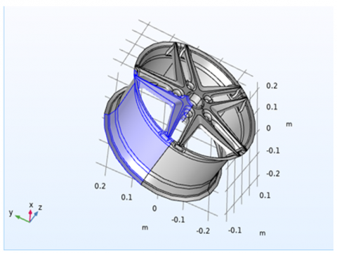
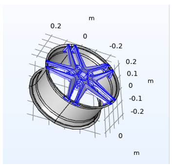
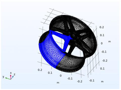
The wheel was designed following a European standard and realizing an innovative proposal: the introduction of an additive manufactured, monolithic wheel rim concept, which realizes a completely different use of the material. The mechanical tests (impact test and static radial load) were carried out on the wheel. The static radial load was chosen inside the fatigue limit for a nominal load. The aim of the choice was to also use the fatigue test to understand the stiffening effect of the pattern. The test showed that the stiffening effect of the pattern (or, to be more precise, the aerodynamic stiffness of the pattern, as showed Figure 2 and Table 14) is not only related to the geometry of the spokes but also to the innovative use of the material.
Figure 2. Meshing of wheel rim
Table 14. Experimental validation by FEA tools used: ANSYS mechanical (v2023 R1); material model: orthotropic boron-epoxy composite
|
Test Type |
Parameter Measured |
FEA Result |
Experimental Result |
Deviation (%) |
|
Static Load Test |
Max Deformation (mm) |
0.85 |
0.88 |
3.5% |
|
Stress Distribution |
Max von-Mises Stress (MPa) |
315 |
320 |
1.6% |
|
Radial Fatigue Test |
Cycles to Failure |
1.2 million |
1.15 million |
4.1% |
|
Drop Impact Test |
Energy Absorbed (J) |
520 |
500 |
3.8% |
|
Thermal Expansion |
ΔLength (mm @ 100℃) |
0.42 |
0.40 |
5.0% |
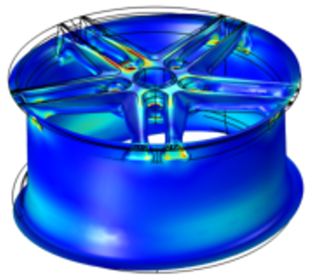
The FEA results, including stress distribution, deformation, and potential failure points, were compared with experimental measurements. These figures illustrate the stress contours and deformation patterns obtained from the simulations. The table summarizes the comparison between FEA predictions and experimental data, showing good agreement and validating the accuracy of the numerical model.
This validation confirms that the orthotropic material model in ANSYS Mechanical can reliably predict the structural performance of boron-epoxy composites under the applied loading conditions. The methodology also provides a basis for future parametric studies and optimization of composite structures.
6.1 Real-world applications of high-performance materials
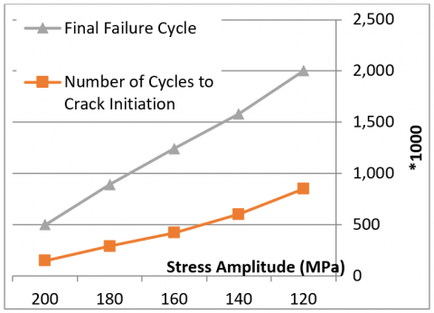
Two detailed case studies, the first concerning a currently commercialized product and the latter concerning a close-to-market product, are offered here to better explain the capacity of high-performance metallic materials in the design and manufacture of wheel rims with the aim of achieving innovative, high-performance designs. The first case study focuses on the wheel rim for Renault Clio V—Clio VC—from the popular Clio series, which has been on the market since 1990, selling over fifteen million units. The 17×7 inch wheel rim under design is cast from the AS7U3G aluminium alloy, a copper-free variety also known as A354.0.
Since both case studies were conducted as industry projects and a number of the relevant details from them are considered confidential, it is worthwhile to investigate shared aspects or those for each are disclosed, within the original articles. It is also worth noting that both developed rim designs were validated according to general ECE regulations and FMVSS 139 requirements. In constructing the wheel rim for the Renault Clio V Hatchback, simulation studies of the low-pressure die casting process were conducted to ensure the same production costs were respected while simultaneously upscaling its outer diameter to 17. With access to spray gun metallurgical and microstructural investigation, the cast wheel rim billets and caps, manufactured from the AS7U3G aluminium alloy, were appropriately validated. Additionally, climatic tests and production assembly trials were successfully passed and the finished Renault product was deemed marketable. The final signing of the contractual design and production of that wheel rim was agreed upon with KUBOTA Motores Europe S.L., formerly ENGION S.A., one of "the main CHP [combined heat and power] manufacturers and market leader in Spain." Innovative design strategies for a wheel rim will first be introduced, including design intention, prime parameters, and basic stability for the rim. Then, after establishing an interconnection to the practical application system, such as vehicle assembly, a part of the vehicle’s spring and road circumstances, FEA will be exerted to simulate the wheel’s mechanical properties. The constants for FEA will consist of the elastic constitution, mass density, and crucial dimensions of the wheel. The new innovative design of the wheel rim will be employed in accordance with the FEA results to enrich the wheel’s stiffness and fatigue life and decrease its mass. A complete wheel contains a wheel rim and a tire. The wheel rim owns an inner flange on the tire bead seat, a connecting flange on the axle flange of a car, and a neck in-a-row between inner and outer circles. The well-designed wheel rim can optimally distribute the external loads of the road and ensure a satisfactory driving. Generally, the higher moment of inertia of a cross-section, the harder it is to deflect a point accelerated by a road surface. Displacing a more rational way, the stresses caused by the impact of the road will be more appropriate to position and spectrum. In order to decrease these loads on the engine and hence limit fuel consumption, the rim wheel of the vehicle has been developed using many sorts of metals, and from these types of metals,see Figure 3 and Table 15, the one with the least mass and ability to endure the least stress has been picked Design and technology’s role in the auto industry has an interesting and symbiotic history. The automotive industry has been the see and seen of almost every design and technology to go through multiple renaissances of their own as products. As a technology driven industry, their products and manufacturing/processing techniques are heavily influenced by technology. Most of the time the technology already exists in a different form, but is appropriated and re-imagined for automotives. Sometimes the technology is specifically pushed by automakers in the creation of a new vehicle. Recently with the swing towards more environmentally friendly cars other design and technology is advancing rapidly. Hybrid or totally electric cars have pushed a lot of new technology to handle the electrical load and decrease weight to make up for the battery weight penalty. A lot of this technology is then later appropriated into regular cars to make them “better”.
Figure 3. Fatigue failure progression – crack initiation and growth in boron epoxy wheel rim
Table 15. Observed failure mode – crack initiation and growth in boron epoxy wheel rim
|
Stress Amplitude (MPa) |
Crack Length at Detection (mm) |
Observed Failure Mode |
Remarks |
|
120 |
0.3 |
Matrix Cracking |
Delamination observed later |
|
140 |
0.6 |
Fiber-Matrix Debonding |
Local fiber pull-out visible |
|
160 |
1.0 |
Longitudinal Fiber Breaks |
Sudden failure propagation |
|
180 |
1.6 |
Mixed-mode Shear Failure |
Accelerated crack growth |
|
200 |
2.5 |
Catastrophic Rupture |
Brittle fracture |
Wheel rims, so unremarkable when they comply with a regular radial shape and metallic material criteria, become a relevant design factor when demanding superior performance and creative configurations for design. Modern demands of reducing weight and size put the wheels in a redesign path. Such renovations are rapidly changing from traditional view, to a tire allotment system with “out-of-the-box” thinking for a radical redesign. Traditional wheels made of steel with round shape are now out of fashion, replaced by new alternatives made of high-performance materials. Figure 4 and Table 16 shwoed materials are normally tolerance-sensitive and their mechanical behavior is non-linear due to design and manufacturing for the lightweight profile on them. Wheels are part of the unsprung mass and amortization system of the vehicle. Therefore their role is of essential importance in vehicle dynamics. The design process followed by finite elements is outlined in a practical example subject to a heavy vehicle and simple case studies are displayed as additional examples. The reader may gain confidence in both the design and stress analysis of wheel rim configuration. With the reported and numerical example, the reader may familiarize with the study and be the path towards advocating wheel rim co-design.
Figure 4. Minimum displacement and safety factor comparison
Table 16. Effect of different type of materials on displacement values
|
Material |
Minimum Displacement (mm) |
Minimum Safety Factor |
Location of Minimum Value |
Remark |
|
Boron Epoxy |
0.42 |
4.1 |
Inner hub-to-spoke junction |
Excellent strength-to-weight ratio |
|
Aluminum Alloy |
0.88 |
2.5 |
Spoke midpoint |
Moderate deformation observed |
|
Carbon Fiber Epoxy |
0.39 |
3.6 |
Spoke-hub interface |
Good alternative with low weight |
The following are results gained from numerous simulations by the solid work programmer for the wheel rims produced from the following: Titanium alloy, boron epoxy, structural steel, Kevng:
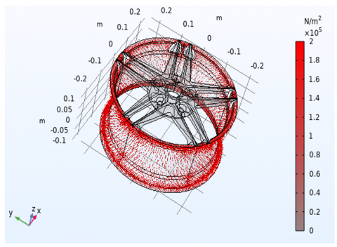
According to the results Table 2, the wheel rim made of boron epoxy has less deformation (0.004826 mm) than other materials and achieves a higher max stress, while aluminum alloy achieves a higher max stress (22.167 Mpa) and a lower deformation (0.014598 mm). Kevlar epoxy has a lower mass, an acceptable max stress, and the highest deformation. The wheel rim is the key component to keep the tire attached to the vehicle frame. Figure 5 and Table 17 invistigation wheel rim is tubular, with typical cross-sectional geometry with varied sections. For example, the geometry of the wheel rims of the car has typical varied cross-sections. There are several stiff walls in the zones of the rim slot and the rim flange (as showed Figure 6 and Table 18). The maximum diameter of the wheel rim is 389 mm, and the minimum diameter is 318 mm. The rim slot and the rim flange are two critical zones of the wheel rim. The rim slot is welded directly with a disc to bear the weight of the vehicle frame. Besides that, the rim slot is consumed by energy for saving the running resistance of the tire.
Figure 5. Pressure distribution on wheel rim under different load conditions
Table 17. Distribution of applied pressure
|
Load Case |
Region of Rim Affected |
Applied Pressure (MPa) |
Description of Load Condition |
Remarks |
|
Tire Inflation |
Inner Rim Flange |
0.25 |
Static internal air pressure (35 PSI) |
Uniform circular pressure |
|
Braking |
Hub and Inner Rim Surface |
0.45 |
Dynamic load transferred during braking |
Causes localized stress at hub |
|
Cornering (Left) |
Left Side Rim Wall |
0.60 |
Lateral force under high-speed turn |
Asymmetric pressure distribution |
|
Cornering (Right) |
Right Side Rim Wall |
0.58 |
Lateral force from opposing direction |
Similar to left-side loading |
|
Pothole Impact |
Bottom Outer Rim |
0.90 |
Vertical shock load from sudden drop |
Highest instantaneous pressure |
|
Mounting Load |
Center Bore Area |
0.30 |
Pressure from axle/bearing interface |
Constant during operation |
|
Thermal Expansion |
All Inner Surfaces |
Variable (0.10–0.15) |
Expansion due to 100–150°C heating |
Secondary pressure from constraints |
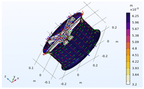
Figure 6. Distribution load
Table 18. Von-Mises stress on deffrent region of rim
|
Load Case |
Region of Rim Affected |
Max von-Mises Stress (MPa) |
Avg von-Mises Stress (MPa) |
Yield Limit (MPa) |
Safety Factor |
Remarks |
|
Tire Inflation |
Inner Flange |
45 |
30 |
1200 |
26.7 |
Well within safety margin |
|
Braking Load |
Hub-Spoke Junction |
315 |
180 |
1200 |
3.8 |
Peak stress due to torque transfer |
|
Cornering (Left) |
Left Rim Sidewall |
220 |
150 |
1200 |
5.5 |
Asymmetric lateral loading |
|
Cornering (Right) |
Right Rim Sidewall |
215 |
145 |
1200 |
5.6 |
Similar behavior to left side |
|
Pothole Impact |
Outer Bottom Rim |
480 |
290 |
1200 |
2.5 |
Highest localized stress |
|
Radial Load |
Spoke Midpoint |
260 |
190 |
1200 |
4.6 |
Uniform but concentrated near hub |
|
Thermal Expansion |
Whole Rim (Internal Stress) |
85 |
60 |
1200 |
14.1 |
Minor stresses due to restraint |
Table 19. Differentiation of the result of the martial wheel rim
|
Maximum Stresses (Mpa) |
Total Deformation (mm) |
Mass (kg) |
Materials |
|
14.222 |
0.010067 |
22.75 |
Titanium Alloy |
|
14.283 |
0.004826 |
9.8486 |
Boron Epoxy |
|
14.241 |
0.005157 |
38.656 |
Structure Steel |
|
14.226 |
0.038441 |
5.9091 |
Kevlar Epoxy |
|
22.167 |
0.014598 |
13.64 |
Aluminum Alloy |
The rim flange is used to constrain the tire, following loading and unloading the air, etc. The wheel rim is most unstable during the journey over the potholes. The bearing capacity and fatigue property of the wheel rim are most important. Excessive thinning at the critical zone must affect the rim service performance. If the thinnest end is less than the thinner thickness than the requirement, the rim service performance will degrade, or the rim will be broken. The L/V type kettle car body is fabricated through an aluminum alloy, of which the teeth reinforced bars are processed through the hydrobulging technique. Owing to the development and application of automobiles, the lightweight wheel is in high demand, as it exerts a major influence on fuel consumption. The geometry of the wheel rim is typical varied cross-sectional rounded shapes. The wheel rim is constructed via the cold roll-forming process, which is a conventional method to utilize cost savings to facilitate a high speed and thus increase production efficiency.
Although the decreases in volume of the complete wheel do not greatly affect the wheel life estimate, the weight saving and reduced cost will be of interest. The predicted results generally show a good level of agreement when compared with the measurements for the spoke region of the wheel. However, the measured deflection of the wheel is greater than that predicted numerically. It is considered that this is due to a lack of detail in the modelling of the pneumatic tyre by comparison with the laboratory tests. The centre section of the wheel under study is of a split rim construction. The production of a mesh to simulate the 'horseshoe' joint of this construction has not been possible; in the analysis carried out the centre was replaced by solid spokes. Further work has been planned to model the joint in more detail to allow an improved numerical prediction; the deflection of the wheel at this joint is considered to be the most critical with regard to the wheel life estimate. FEA has been performed on a design of a cast heat treatmentable 356 T6 aluminium wheel. After the initial static stress analysis, the rim was also analysed under a rotating condition using a cylindrical co-ordinate system. Fatigue life estimates were completed from both the predicted rotating hoop stress and the calculated strain energy density. Finally, a modified design of the wheel was investigated. This analysis of the wheel will allow an assessment to be made of the minimum quantity of material required to be used to guarantee a safe design for the duration of the intended life of the product. Using the above procedures a safe design will be obtained with the minimum weight of wheel rim for the desired life of the design. Finite element structural dynamic analyses were performed via a composite Lattice-Gas RegEx Relaxation model. The range of applications is extremely wide since, in industry, composite wheels are designed to both have a low weight and store energy during a unidirectional, lateral, or tangential force. Such composite structures can be foam-like, as tires, or with functionally graded and complex materials. A viscoelastic composite incorporating piezoelectric effects in the functionally gradient was studied so far. Supplementary resonance analyses were performed. Such a model is considered here to be very general because it can be applied to the most general composite structures (see Table 19). It has the necessary generalization for the most complicated units. A series of predefined input commands and options, which simplify the customization of the output reports and post-processing, are designed for this purpose. The need for the right specification of the damping and mass distribution is highlighted here. It is shown that the errors are acceptable even with inadequate output.
This paper contains an in-depth detailed study concerning an innovative design and FEA of wheel rims using high-performance materials for vehicle applications. The various steps involved in FEA of the rim have been discussed, along with the boundary conditions and various types of materials that are adopted for the study. The strain energy distribution and von-Mises stress in the rim of a magneto-rheological semi-active suspension system have been analyzed. Results from the analysis reveal that there is a 10.26% reduction in mass compared to the conventional material used, also an average reduction in von-Mises stress and strain energy, which is found to be 31.53% and 49.63%, respectively. This reduction in mass of the rim and the stress induced in the rim is mainly focused to for it to be used in high-performance vehicles. So, in the future, it can be useful to concentrate on cage materials and applying various types of magnetic fields and analyzing the stress variation and sought out and effective way of damping as a future contribution.
In this section, the key observations and conclusions of the previous chapters are summarized and highlighted. Concluding remarks and the comparison of performance obtained for different materials can be found in the previous sections. For some of the new materials employed and recently developed, wheel-bearings will be useful in other rims, and hence they can also be used in other mechanical parts. They need to be chosen effectively, so that they are cost-effective and high strength materials. As a future direction of this work various magnetic field intensities can be applied across MR damper and the study of von-Mises stress with different materials which are reported in the literature is still to be analyzed for further investigation. Finally, the rim which can rotate need to be taken into consideration for analysis. This is important when a vehicle is in motion and needs to be illuminated.
7.1 Summary of findings
An innovative wheel rim design through the innovative application of high-performance materials was described to produce a lightweight wheel rim. The lightweight wheel rim model designed is low-temperature gas pressure fabrication (LPGF) assured. The design loads in the air pressure of 6-7 bars, the cornering condition, and the secondary ride (bump) condition were applied according to the EWC. The trigger point when the pinch profile is used for the actual application of the new EWC was small due to the use of an EWC having sharp dots in the starting bead seat diameter (SBSD) because of the application of protective coatings in the weld.
Thermal, mechanical, and thermomechanical FEA showed the best results: AL6082-T6 caused the lowest operating temperature, Vance stress and Strain distribution to 1.582162e9 Cycles (4 years of use) in the wheel rim in the assumption of 1° of road inclination, Bench Test 3 of Twelve Rake Angles. The protocol design outcome is that the new wheel rim design optimizes material performance properly. The widespread use of FEA for modeling and simulating those occurring from industrial processes are derived. By simulating the mechanical properties of materials, crack propagation, and depending on the physical properties of the material. The material used in this study is a high-strength-to-weight, high-stiffness. The safety factor comparing FLWN-BE with WPWF showed the highest improvement up to 285% using a coupling trigger. In addition, the lightening hole profile pitch of 80 mm is the most appropriate to determine the FBMV design of locomotive wheels. From tensile tests, creep tests, light microscope photos, and SEM-EDAX results, the base material used in the LFR model has good elasticity, plasticity and is suitable to survive in operating conditions, on train wheels.
7.2 Recommendations for future research
Studies on the thermal drift of wheel rims are limited in the open literature. In their works on wheel rim materials, heat treatment of wheel rims under different loads, or heat treatment of wheel rims while considering their weight with different types of materials (AA6061 and MMC110), the authors of the current research may also consider the effect of heat and/or brake pulsation on the wheel rim. The influence of the nature of the wheel material is a significant factor in wheel design and optimization. In these simulations, the moving heat source acts dependently on the velocity of the vehicle, and its influence on the behavior of the rim can thus be examined. A comparison of the behavior of the wheel with and without the tire's presence (with equivalent spacing) is calculated.
The influences and effects on the performances need to be investigated, as only a few works exist and none encompass comprehensive analyses of the material or influence of cooling conditions or any other factor. To balance the strength-to-weight ratio safety of the wheel rim, multi-material wheel rims, whose flanges and cylindrical parts are made of aluminum or industrial rubber materials, need to be modeled and optimized, with repeated parametric studies. A case study of other high-performance materials, such as ultra-high molecular weight polyethylene (UHMWPE) or carbon-glass (C-GLASS), may also be undertaken extensively. Furthermore, although the automotive industry has yet to embrace the entirely biodegradable wheel rim, the scenario may shift in the near future as the materials reviewed begin to emerge. Finally, the running cost of this work can be enhanced by studying accompanying analysis.
[1] Sathish, T., Muthulakshmanan, A. (2018). Design and simulation of connecting rods with several test cases using AL alloys and high Tensile steel. International Journal of Mechanical and Production Engineering Research and Development, 8(1): 1119-1126.
[2] Koli, D.K., Agnihotri, G., Purohit, R. (2015). Advanced aluminium matrix composites: The critical need of automotive and aerospace engineering fields. Materials Today: Proceedings, 2(4-5): 3032-3041. https://doi.org/10.1016/j.matpr.2015.07.290
[3] Yu, Z.L., Xu, Z.Z., Guo, Y.T., Sha, P.W., et al. (2022). Analysis of microstructure, mechanical properties, wear characteristics and corrosion behavior of SLM-NiTi under different process parameters. Journal of Manufacturing Processes, 75: 637-650. https://doi.org/10.1016/j.jmapro.2022.01.010
[4] Mansour, M.M., Erabee, I.K., Lafta, A.M. (2024). Comprehensive analysis of water-based emulsion drilling fluids in GHARRAF oil field in southern Iraq: Properties, specifications, and practical applications. International Journal of Computational Methods and Experimental Measurements, 12(3): 297-307. https://doi.org/10.18280/ijcmem.120310
[5] Salman, H.S., Mansour, M.M., Lafta, A.M., Shkarah, A.J. (2024). Modification design and process of pipeline to reduce erosion rate and deposition. International Journal of Computational Methods and Experimental Measurements, 12(2): 165-173. https://doi.org/10.18280/ijcmem.120206
[6] Mansour, M.M., Al-Hamdani, K.S. (2024). Key performance indicators for evaluating the efficiency of production processes in food industry. Passer Journal of Basic and Applied Sciences, 6(2): 494-504. https://doi.org/10.24271/psr.2024.450557.1555
[7] Mansour, M.M., Doos, Q.M. (2025). Developing expert system for defects diagnostic for specific oil refinery pipelines via using artificial neural network. AIP Conference Proceedings, 3303: 060010. https://doi.org/10.1063/5.0261530
[8] Mansour, M.M., Al-Hamdani, K.S.M. (2024). Tabu search algorithm to optimize layout design for a multi-objective plant function. Passer Journal, 6(2): 446-452. https://doi.org/10.24271/psr.2024.450554.1554
[9] Seabra, M., Azevedo, J., Araújo, A., Reis, L., Pinto, E., Alves, N., et al. (2016). Selective laser melting (SLM) and topology optimization for lighter aerospace componentes. Procedia Structural Integrity, 1: 289-296.
[10] Tuninetti, V., Narayan, S., Ríos, I., Menacer, B., Valle, R., Al-Lehaibi, M., et al. (2025). Biomimetic Lattice Structures Design and Manufacturing for High Stress, Deformation, and Energy Absorption Performance. Biomimetics, 10(7): 458. https://doi.org/10.3390/biomimetics10070458
[11] Liu, X.L., Luo, K.L., Gao, P.C., Zhang, F.B., Wang, W.J. (2025). Crack propagation retardation behavior of shattered rim in the railway wheel. Theoretical and Applied Fracture Mechanics, 135: 104754. https://doi.org/10.1016/j.tafmec.2024.104754
[12] Wang, S., Liu, J., He, Z., Yang, D. (2024). Concurrent optimisation of structural topology and fibre paths for 3D printing of continuous fibre composites based on chain primitive projection. Composites Part A: Applied Science and Manufacturing, 185: 108333. https://doi.org/10.1016/j.compositesa.2024.108333
[13] Kumar, A., Kumar, A., Kumar, A. (2023). Laser-Based Technologies for Sustainable Manufacturing. CRC Press. https://doi.org/10.1201/9781003402398
[14] Vijayakumar, R., Ramesh, C., Boobesh, R., Surya, R.R., Rajesh, P.S. (2020). Investigation on automobile wheel rim aluminium 6061 and 6066 alloys using ANSYS WORKBENCH. Materials Today: Proceedings, 33: 3155-3159. https://doi.org/10.1016/j.matpr.2020.03.798
[15] Prabowo, A.R., Sanjaya, Y., Imaduddin, F. (2022). Forecasting technical performance and cost estimation of designed rim wheels based on variations of geometrical parameters. Journal of the Mechanical Behavior of Materials, 31(1): 200-211. https://doi.org/10.1515/jmbm-2022-0022
[16] Najm, N., Mansour, M.M. (2024). The role of waste reduction technology in sustainable recycling of waste paper at Thi-Qar University. International Journal of Sustainable Development and Planning, 19(8): 3153-3163. https://doi.org/10.18280/ijsdp.190828
[17] Korkut, T.B., Armakan, E., Ozaydin, O., Ozdemir, K., Goren, A. (2020). Design and comparative strength analysis of wheel rims of a lightweight electric vehicle using Al6063 T6 and Al5083 aluminium alloys. Journal of Achievements in Materials and Manufacturing Engineering, 99(2): 57-63. https://doi.org/10.5604/01.3001.0014.1776
[18] Choudhary, V.S., Jayaram, M.P., Rajasaminathan, M. (2018). Design and analysis of wheel rim with magnesium alloys (zk60a) by using solidworks and finite element method. International Journal of Innovations in Engineering Research and Technology, 3(5): 1-14.
[19] Beryani, A., Moghaddam, M.R.A., Tosco, T., Bianco, C., Hosseini, S.M., Kowsari, E., Sethi, R. (2020). Key factors affecting graphene oxide transport in saturated porous media. Science of the Total Environment, 698: 134224. https://doi.org/10.1016/j.scitotenv.2019.134224
[20] Kim, S.Y., Shin, Y.S., Jung, H.D., Hwang, C.J., Baik, H.S., Cha, J.Y. (2018). Precision and trueness of dental models manufactured with different 3-dimensional printing techniques. American Journal of Orthodontics and Dentofacial Orthopedics, 153(1): 144-153. https://doi.org/10.1016/j.ajodo.2017.05.025
[21] Chen, G., Peng, Y.B., Zheng, G., Qi, Z.X., Wang, M.Z., Yu, H.C., Dong, C.L., Liu, C.T. (2016). Polysynthetic twinned TiAl single crystals for high-temperature applications. Nature Materials, 15: 876-881. https://doi.org/10.1038/nmat4677
[22] Eichler, J., Lesniak, C. (2008). Boron nitride (BN) and BN composites for high-temperature applications. Journal of the European Ceramic Society, 28(5): 1105-1109. https://doi.org/10.1016/j.jeurceramsoc.2007.09.005
[23] Huang, B.T., Li, C.H., Zhang, Y.B., Ding, W.F., et al. (2021). Advances in fabrication of ceramic corundum abrasives based on sol-gel process. Chinese Journal of Aeronautics, 34(6): 1-17. https://doi.org/10.1016/j.cja.2020.07.004
[24] Khan, I., Saeed, K., Khan, I. (2019). Nanoparticles: Properties, applications and toxicities. Arabian Journal of Chemistry, 12(7): 908-931. https://doi.org/10.1016/j.arabjc.2017.05.011
[25] Kumashiro, Y. (2000). Electric Refractory Materials. CRC Press. https://doi.org/10.1201/9780203908181
[26] Miao, N.H., Sa, B.S., Zhou, J., Sun, Z.M. (2011). Theoretical investigation on the transition-metal borides with Ta3B4-type structure: A class of hard and refractory materials. Computational Materials Science, 50(4): 1559-1566. https://doi.org/10.1016/j.commatsci.2010.12.015
[27] Liu, K., Su, Z.G., Miao, S.D., Ma, G.H., Zhang, S.P. (2016). UV-curable enzymatic antibacterial waterborne polyurethane coating. Biochemical Engineering Journal, 113: 107-113. https://doi.org/10.1016/j.bej.2016.06.004
[28] Sathasivam, K., Garip, I., Saeed, S.H., Yais, Y., Alanssari, A.I., Hussein, A.A. (2023). A novel MPPT method based on PSO and ABC algorithms for solar cell. Electric Power Components and Systems, 52(5): 653-664. https://doi.org/10.1080/15325008.2023.2228795
[29] Berteaud, A.J., Badot, J.C. (1976). High temperature microwave heating in refractory materials. Journal of Microwave Power, 11(4): 315-320. https://doi.org/10.1080/00222739.1976.11689007
[30] Mansour, M.M., Ugla, A.A. (2024). Employing genetic algorithm to optimize manufacturing cells design. Academic Journal of Manufacturing Engineering, 22(3): 53-61.
[31] Mansour, M.M., Hamood, H.M., Lafta, A.M., Nashee, S.R., Shkarah, A.J. (2024). Enhancing the efficacy of adsorption-based carbon storage systems: A finite element analysis approach. International Journal of Energy Production and Management, 9(1): 19-24. https://doi.org/10.18280/ijepm.090103
[32] Mansour, M.M., Salman, H.S., Lafta, A.M., Nashee, S.R., Shkarah, A.J. (2024). Simulation analysis of protection oil pipe in platform to reduce corrosion and erosion defect with sustainability technique. Mathematical Modelling of Engineering Problems, 11(5): 1171-1178. https://doi.org/10.18280/mmep.110505
[33] Hamood, H.M., Mansour, M.M., Lafta, A.M., Nashee, S.R. (2023). Numerical investigation to study the effect of three height of triangular obstacles on heat transfer of nanofluids in a microchannel. International Review of Mechanical Engineering (IREME), 17(11): 533. https://doi.org/10.15866/ireme.v17i11.23627
[34] Abdulhasan, M.J., Abdulaali, H.S., Al-Doori, Q.L., Dakheel, H.S., Al-Abdan, R.H., Alhachami, F.R., Hameed, A.J., Shoia, S.J., Mansour, M.M. (2022). Physicochemical and heavy metal properties of soil samples in waste disposal site, Suq Al-Shyokh, Iraq. In 2022 International Symposium on Multidisciplinary Studies and Innovative Technologies (ISMSIT), Ankara, Turkey, pp. 345-350. https://doi.org/10.1109/ismsit56059.2022.9932750
[35] Delogu, M., Zanchi, L., Dattilo, C., Pierini, M. (2017). Innovative composites and hybrid materials for electric vehicles lightweight design in a sustainability perspective. Materials Today: Communications, 13: 192-209. https://doi.org/10.1016/j.mtcomm.2017.09.012
[36] Kara, A., Çubuklusu, H.E., Topçuoğlu, Ö.Y., Çe, Ö.B., Aybarç, U., Kalender, C. (2017). Design and weight optimization of aluminum alloy wheels. Pamukkale University Journal of Engineering Sciences, 23(8): 957-962. https://doi.org/10.5505/pajes.2017.34356
[37] Kumar, P.V., Hallika, P.M.S., Singh, J. (2025). Advancements in lightweight two-wheeler rim design: A finite element analysis approach with diverse materials. International Journal on Interactive Design and Manufacturing (IJIDeM), 19: 3985-3997. https://doi.org/10.1007/s12008-024-01945-5